
Yanmar SV100-1 Crawler Excavator Parts Catalog 0CS10-G54500 – PDF
Original price was: $34.95.$19.95Current price is: $19.95.
Illustrated parts catalogue for the Yanmar SV100-1 crawler back-hoe (US, AS, NZ) and its 4TNV98T-ZSBV1 engine. Document 0CS10-G54500, 1st edition, Nov. 2008 – every figure, ref. number and part number for the complete machine.
Description
The Yanmar SV100-1 Crawler Excavator Parts Catalog 0CS10-G54500 is the illustrated parts catalogue for the SV100-1 crawler back-hoe (excavator) built for the U.S.A., Australia and New Zealand markets. Issued as the 1st edition in November 2008, it lists the complete machine by figure, reference number, part number and description – from the safety labels on the bonnet through to the swivel joint under the turning frame, together with the parts for the 4TNV98T-ZSBV1 engine installation.
File Details
- Manual type: Illustrated parts catalogue (parts catalog)
- Brand: Yanmar
- Model: SV100-1 (US, AS, NZ)
- Engine: 4TNV98T-ZSBV1
- Vehicle parts catalog number: 0CS10-G54500
- Engine parts catalog number: 0CS10-G77200
- Edition: 1st edition
- Published: Nov., 2008
- Language: English
- Format: PDF
Chapters Covered
The catalogue is organised into numbered figures, each with its own exploded or pictorial illustration and a matching parts table:
- Fig. 1 – Label; Fig. 2 – Safety Label
- Fig. 3 – Muffler; Fig. 4 – Air Cleaner; Fig. 5 – Accelerator
- Fig. 6 – Engine Mount; Fig. 7 – Radiator; Fig. 8 – Radiator Mount
- Fig. 9 – Sub-Tank; Fig. 10 – Fuel Tank; Fig. 11 – Fuel Line
- Fig. 12-20 – Electric Parts (engine, control valve plate, battery, starting switch, air conditioner, switch box for quick coupler, seat mount, work lamp, indicator box) and Fig. 118 (20A) Electric Part cover
- Fig. 21 – Travel Alarm
- Fig. 22-25 – Air Conditioner (cabin related, piping, engine related, condenser related)
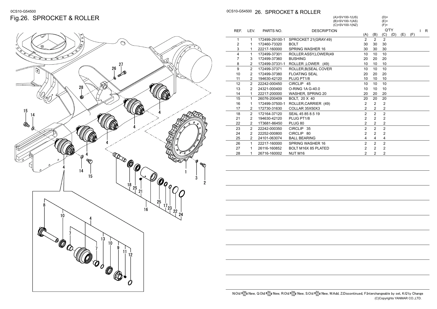
- Fig. 26 – Sprocket & Roller; Fig. 27 – Idler & Adjust; Fig. 28 – Crawler
- Fig. 29-33 – Control Equipment (lock lever & lever stand, travel, blade, swing) and Arm Rest
- Fig. 34 – Travel Frame; Fig. 35 – Turning Frame & Turning Bearing
- Fig. 36-40 – Covers (fuel tank side, center, seat mount A and B, turning frame, travel frame)
- Fig. 41 – Floor Mat & Instrument Panel; Fig. 42 – Seat & Seat Mount
- Fig. 43-46 – Bonnet (body, rear, side left, side right); Fig. 47 – Cabin Mount
- Fig. 48-56 – Cabin (body, door, front window 1 and 2, window sash & lower glass, electric, washer tank) plus rear-view mirror, cabin accessory and side mirror
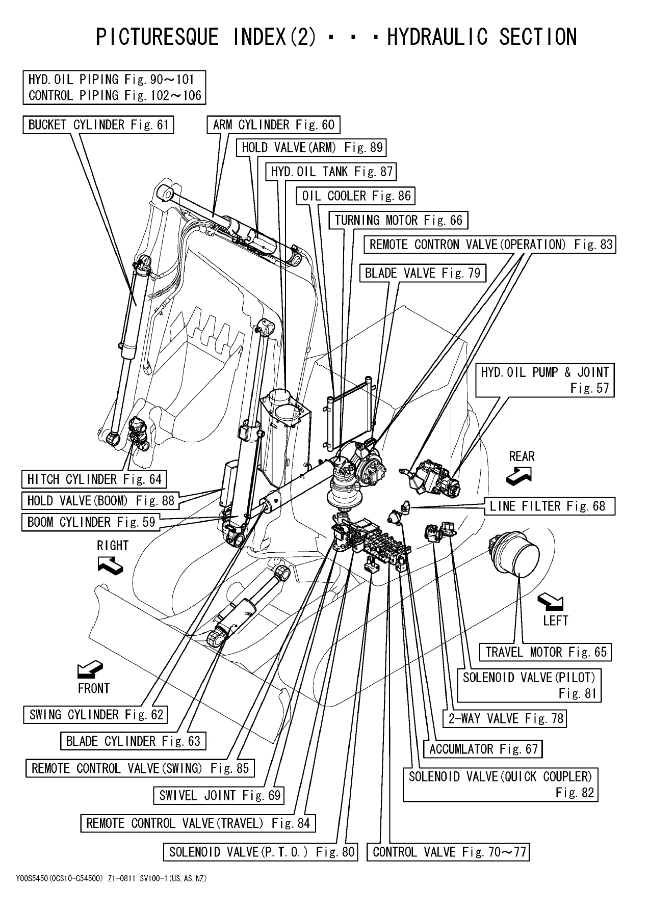
- Fig. 57 – Hyd. Oil Pump & Joint; Fig. 122 (57A) Hyd. Oil Pump & Joint (from M11514)
- Fig. 58 – Control Valve Plate
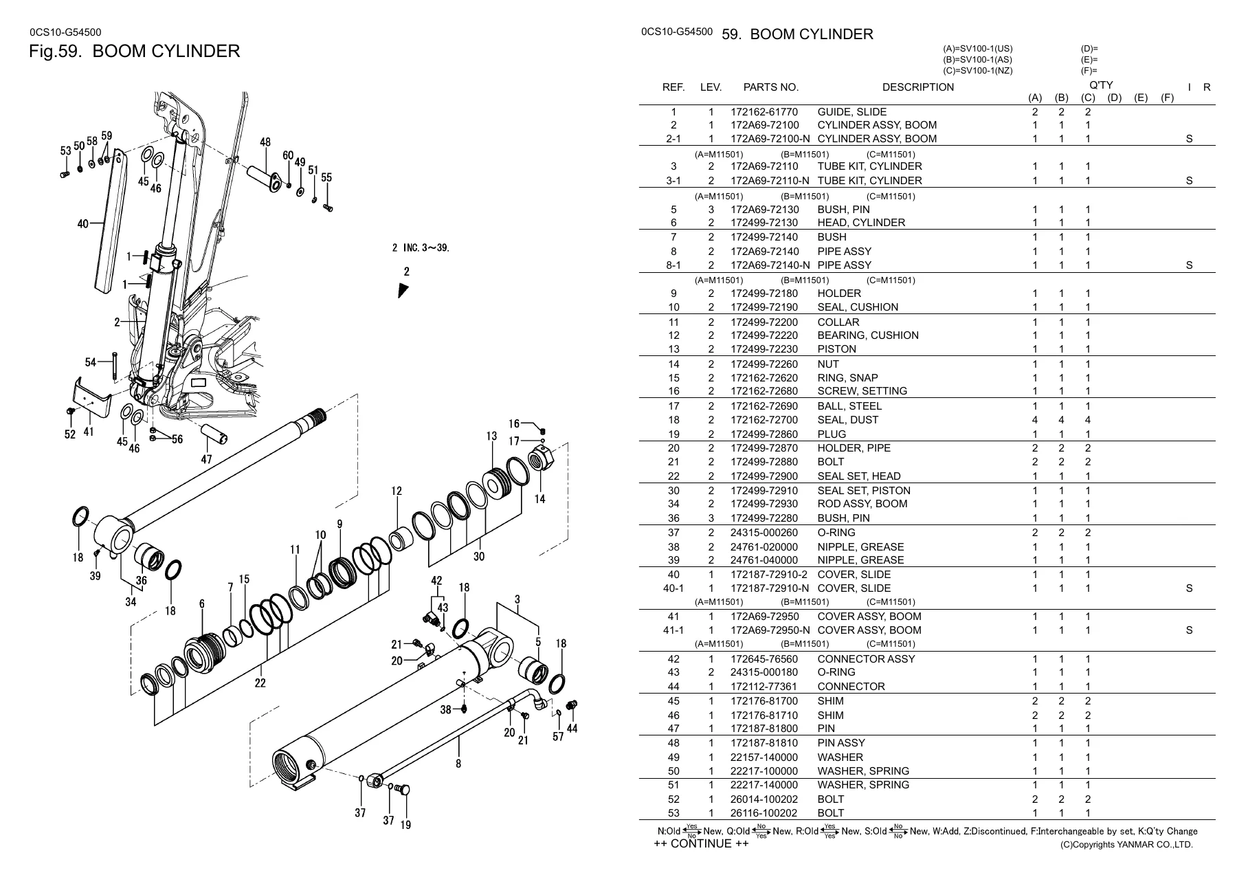
- Fig. 59 – Boom Cylinder; Fig. 60 – Arm Cylinder; Fig. 61 – Bucket Cylinder; Fig. 62 – Swing Cylinder; Fig. 63 – Blade Cylinder; Fig. 64 – Hitch Cylinder
- Fig. 65 – Travel Motor; Fig. 66 – Turning Motor (KY); Fig. 120 (66A) Turning Motor (NA)
- Fig. 67 – Accumulator; Fig. 68 – Line Filter
- Fig. 69 – Swivel Joint (Y spec.); Fig. 123 (69A) Swivel Joint (N spec.) and Fig. 124 (86B) Swivel Joint Kit (N spec.)
- Fig. 70-77 – Control Valve sections 1/8 through 8/8
- Fig. 78 – 2-Way Valve; Fig. 79 – Blade Valve
- Fig. 80 – Solenoid Valve (P.T.O.); Fig. 81 – Solenoid Valve (Pilot); Fig. 82 – Solenoid Valve (Quick Coupler)
- Fig. 83-85 – Remote Control Valve (operation, travel, swing)
- Fig. 86 – Oil Cooler; Fig. 87 – Hyd. Oil Tank; Fig. 88 – Hold Valve (Boom); Fig. 89 – Hold Valve (Arm)
- Fig. 90-101 – Hyd. Oil Piping (pump to control valve to oil cooler; tank to pump and swing cylinder; control valve to turning motor; fittings; control valve to boom, turning motor and tank; control valve to swivel joint; track frame; boom; P.T.O. frame end; P.T.O. arm end; quick coupler; hold valve)
- Fig. 102-106 – Control Piping (control valve to solenoid valve, control valve to 2-way valve, 2-way valve to remote control valve, travel and swing pedal, P.T.O.)
- Fig. 107 – Greasing
- Fig. 108 – Boom Bracket; Fig. 109 – Boom; Fig. 110 – Arm; Fig. 111 – Bucket Arm & Link
- Fig. 112 – Quick Coupler; Fig. 113 – Bucket Pin; Fig. 114 – Blade
- Fig. 115 – CA Label Kit (optional); Fig. 116 – Air Conditioner (unit, condenser: inner parts)
- Fig. 117 – Additional Weight (optional); Fig. 121 – Hold Valve (optional)
- Part Number Index – all part numbers listed in ascending order with their figure and reference number
For anyone maintaining or rebuilding an SV100-1, this is the lookup layer that sits underneath the workshop manual: you identify the assembly on the illustration, read off the reference number, then jump to the parts table for the exact part number, description and the quantities required per machine. It covers the vehicle and the engine installation side by side, so a single document answers questions about a blown hydraulic hose, a cracked cab glass, a missing label, a worn sprocket or a replacement solenoid valve without switching between books. Machine serial-number break points are printed throughout, which is what allows the correct superseded or current part to be picked for a particular build.
How the Parts Catalogue Is Read
Each figure uses the same table layout, and the catalogue explains its own conventions on its opening pages:
- REF. NO. – the callout on the illustration. Where a part has changed, the illustration and list reference numbers may differ slightly (for example, list Ref. No. 1 against illustration 1-1 after a change).
- LEV. (Level) – shows how deeply a part sits inside an assembly: level 1 is a main assembly part, level 2 is a sub-component of level 1, level 3 is a sub-component of level 2.
- PART NO. and DESCRIPTION – the orderable part number and its description as printed.
- QTY columns (A) to (F) – quantities for the applicable model variants. Column (A) is SV100-1 (US), (B) is SV100-1 (AS), (C) is SV100-1 (NZ).
- I / R marks – interchangeability symbols. N means the new part fits the old but not the reverse; Q means the old part fits the new but not the reverse; R means both directions interchange; S means neither direction interchanges; W marks a newly added part; Z marks a discontinued part; F means the parts only interchange as a set; K means a change in used quantity only.
- Effective Machine No. – letters such as E (engine), M (machine), C (clutch) and D (drive) followed by the serial at which the change took effect, shown against the relevant column. Dates may follow a symbol, and XXXXX or ZZZZZ indicate a value that could not be predicted.
What This Parts Catalog Lets You Do
With the Yanmar SV100-1 parts catalogue 0CS10-G54500 open you can order the right component the first time – not a lookalike. The hydraulic sections alone cover the pump and joint, the eight control valve sections, the boom, arm, bucket, swing, blade and hitch cylinders, the travel and turning motors, the accumulator, line filter, swivel joint, hold valves, oil cooler and every piping run between them, so a leaking fitting or a failed relief valve can be traced from the diagram straight to a part number. The undercarriage figures break down the sprocket, lower and carrier rollers, idler and adjuster, and the complete crawler link, bush, pin and shoe assemblies down to individual nuts and bolts.
On the structure and cab side, the same approach applies to the travel frame, turning frame and swing bearing, the counterweight, the bonnet panels, the cabin body, door glass, front window slides and latches, the wiper motor, work lamps and the air conditioning unit, condenser, piping and receiver dryer. The electric part figures map the harnesses, fuses, relays, controller boxes and switches fitted to each market variant, and the label figures list each safety and information decal with its own part number – useful when a machine has been repainted or repaired and a warning decal is missing.
Correct part identification matters on a machine like the SV100-1 because superseded components, market-specific variants and serial-number break points all affect what will actually fit. Working from an illustrated parts catalog rather than a generic listing means the level structure, the quantity per machine and the interchangeability mark are all visible before anything is ordered.
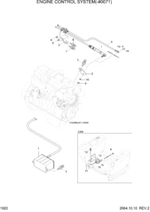
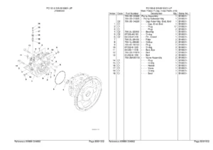
IMAGES PREVIEW
The Yanmar SV100-1 Crawler Excavator Parts Catalog 0CS10-G54500 is delivered as an instant PDF download – no shipping, no waiting for a disc. It opens on a workshop PC, laptop, tablet or phone, pages can be printed for the bench, and the Part Number Index at the back lets you search a part number you already have and find exactly which figure and reference number it belongs to.
Reviews
There are no reviews yet.