★ TRUSTED BY 321,897+ PROFESSIONALS WORLDWIDE
🏒
Trusted Business
Verified & Licensed
πŸ›‘οΈ
Virus Free Files
100% Safe Downloads
πŸ”’
Secure Payment
SSL Protected
⚑
Instant Delivery
Available Immediately
Sale!

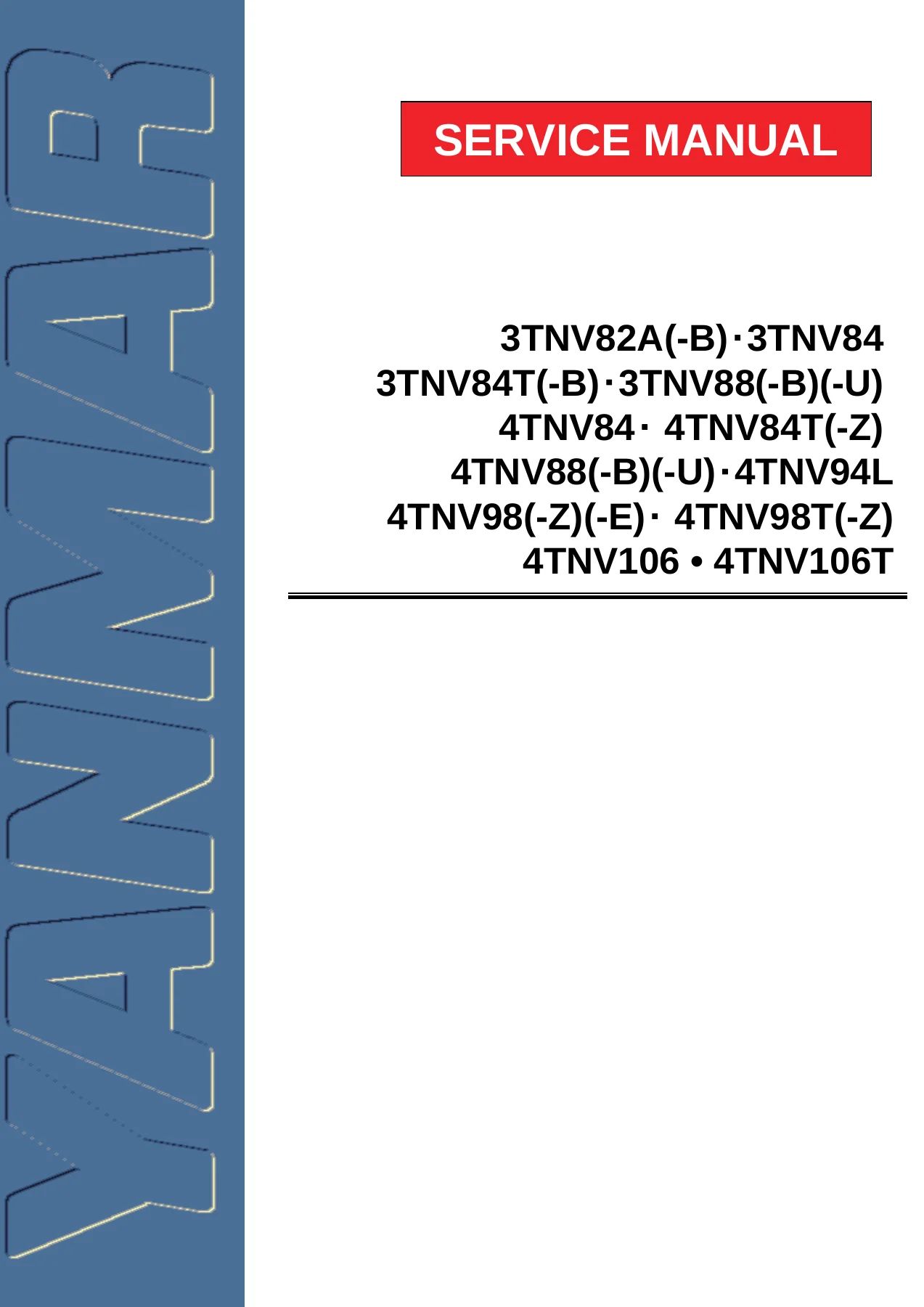
Yanmar TNV Series Diesel Engine Service Manual – 3TNV82A to 4TNV106T Repair PDF

Original price was: $39.95.Current price is: $24.95.

Complete Yanmar TNV Series service manual covering all 3TNV and 4TNV industrial diesel engines. Includes engine overhaul, fuel system, cooling, lubrication, turbocharger, starter, alternator, electrical wiring, and troubleshooting procedures.

⚑
Instant PDF Download
Available immediately
πŸ’Ύ
Save to Your Device
Download & keep forever
πŸ›‘οΈ
Antivirus Scanned
100% virus-free
🌍
Trusted Worldwide
175,000+ customers

Description

Yanmar TNV Series Diesel Engine Service Manual

This Yanmar TNV Series Service Manual is a complete workshop guide for the full range of TNV direct injection industrial diesel engines. From the compact 3-cylinder 3TNV82A to the turbocharged 4-cylinder 4TNV106T, this manual provides the procedures, specifications, and torque data needed for professional engine service and repair.

File Details

  • Manual Type: Service / Workshop Manual
  • Brand: Yanmar
  • Document Number: 0BTNV-G00101
  • Publication Date: 2005
  • Language: English
  • Page Count: 625
  • File Format: PDF
  • Models Covered: 3TNV82A, 3TNV82A-B, 3TNV84, 3TNV84T, 3TNV84T-B, 3TNV88, 3TNV88-B, 3TNV88-U, 4TNV84, 4TNV84T, 4TNV84T-Z, 4TNV88, 4TNV88-B, 4TNV88-U, 4TNV94L, 4TNV98, 4TNV98-Z, 4TNV98-E, 4TNV98T, 4TNV98T-Z, 4TNV106, 4TNV106T

Chapters Covered

  • Introduction β€” Manual scope and usage for TNV direct injection engines.
  • Yanmar Warranties β€” Standard limited warranty, emission control system warranty, retail purchaser registration.
  • Safety β€” Safety statements, precautions, and hazard warnings.
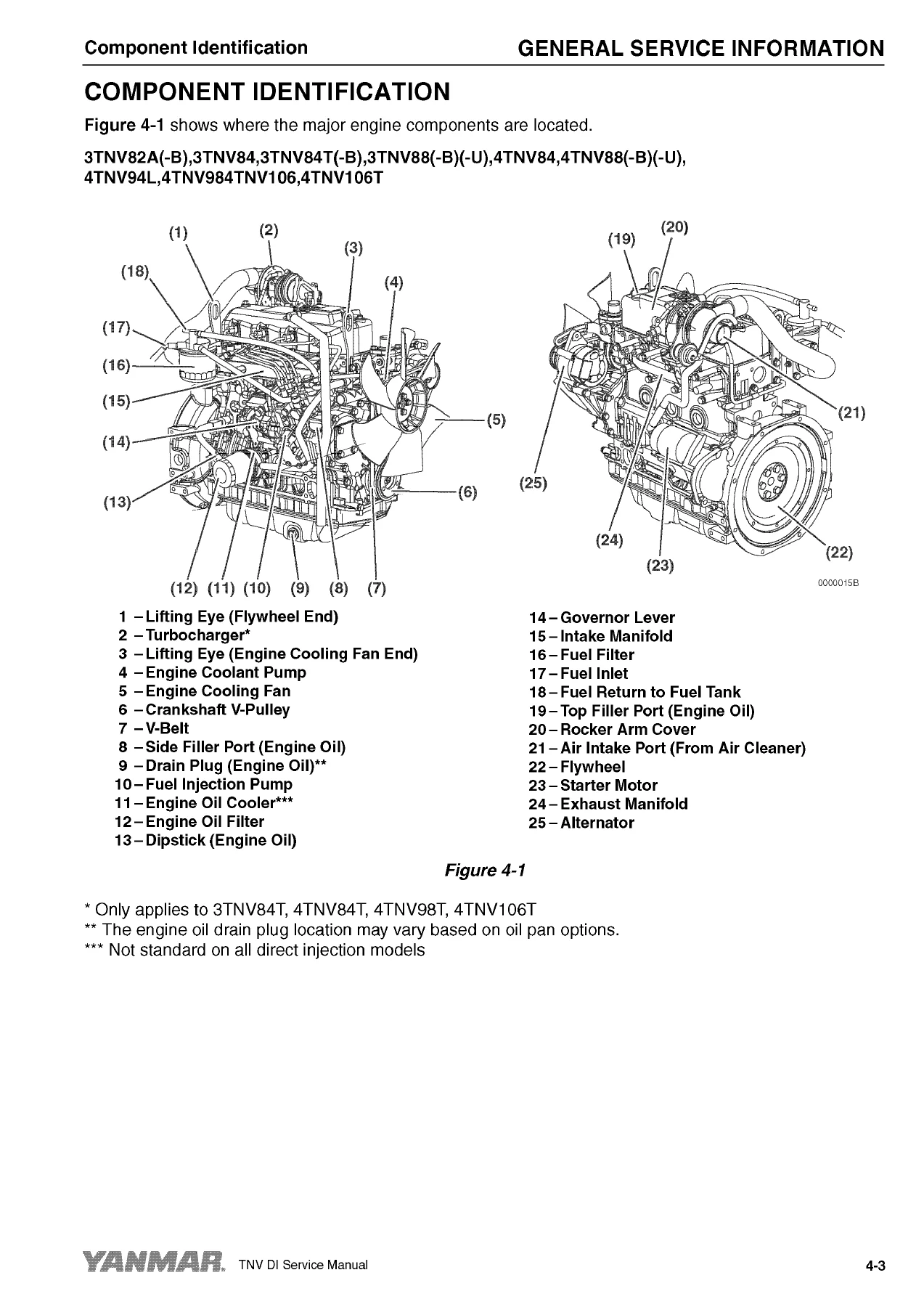
  • General Service Information β€” Component identification, location of labels, engine nameplate, emission control regulations (EPA / ARB, 97/68/EC Directive), engine family designation, function of major engine components, electronic control components, cooling system components, diesel fuel specifications, fuel tank filling, fuel system priming, engine oil specifications and viscosity, oil level checking, engine coolant specifications, radiator filling, engine speed specifications, principal engine specifications by model, engine service standards, tightening torques for standard bolts and nuts, abbreviations and symbols, unit conversions.
  • Periodic Maintenance β€” Before you begin servicing, importance of periodic maintenance, Yanmar replacement parts, required EPA / ARB maintenance, EPA / ARB installation requirements, periodic maintenance schedule, after initial 50 hours, every 50 hours, every 250 hours, every 500 hours, every 1000 hours, every 1500 hours, every 2000 hours.
  • Engine β€” Cylinder head specifications, intake/exhaust valve and guide, push rod, rocker arm and shaft, valve spring, camshaft and timing gear train specifications, idler gear shaft and bushing, timing gear backlash, crankshaft and piston specifications, thrust bearing, piston ring, connecting rod, tappet, cylinder block specifications, special torque chart, special service tools, measuring instruments, 2-valve cylinder head (components, disassembly, cleaning, inspection, reassembly), 4-valve cylinder head (components, disassembly, cleaning, inspection, reassembly), measuring and adjusting valve clearance, crankshaft and camshaft components, disassembly of engine, disassembly of camshaft and timing components, disassembly of crankshaft and piston components, inspection of crankshaft and camshaft components, honing and boring, reassembly of crankshaft and piston components, reassembly of camshaft and timing components, final reassembly of engine, EGR system.
  • Fuel System β€” Fuel injection pump, fuel injectors, high-pressure lines, fuel filter, testing and adjustment.
  • Cooling System β€” Engine coolant pump, thermostat, radiator, temperature switch.
  • Lubrication System β€” Oil pump, oil filter, oil cooler, pressure checks.
  • Turbocharger β€” Inspection, blower wash, waste gate actuator, periodic inspection.
  • Starter Motor β€” No-load test, disassembly, inspection, reassembly.
  • Alternator β€” Charging system, disassembly, inspection, installation.
  • Electric Wiring β€” Wiring diagrams, battery cable resistance, connectors.
  • Troubleshooting β€” Diagnostic charts, compression testing, fault diagnosis by symptom.

This Yanmar TNV Series service manual is a complete engine workshop reference covering the full lifecycle of these industrial diesel engines. It takes you from initial break-in and daily checks through scheduled maintenance and into complete teardown, inspection, machining, and reassembly. The manual includes detailed specifications for every covered model, special service tools, measuring instruments, and step-by-step procedures supported by illustrations and exploded views.

The engine section is particularly comprehensive, covering both 2-valve and 4-valve cylinder heads with separate procedures for disassembly, cleaning, inspection, and reassembly. Torque values, wear limits, and clearance specifications are provided throughout. The fuel system, cooling system, lubrication system, turbocharger, starter motor, alternator, and electrical wiring sections give you the diagnostic and repair information needed for all major engine systems.

What This Manual Enables You to Do

  • Perform complete engine overhauls on all TNV series models
  • Service both 2-valve and 4-valve cylinder heads
  • Adjust valve clearance, injection timing, and governor settings
  • Diagnose and repair fuel system faults
  • Service the cooling system, including coolant pump and thermostat
  • Inspect and rebuild the lubrication system
  • Inspect, clean, and blower-wash turbochargers
  • Test and repair starter motors and alternators
  • Troubleshoot electrical faults using wiring diagrams
  • Perform scheduled maintenance at 50, 250, 500, 1000, 1500, and 2000-hour intervals
  • Measure and evaluate wear against factory service limits
  • Source or fabricate special service tools

Why This Manual Matters

Yanmar TNV series engines power a wide range of industrial, agricultural, and construction equipment. Using the correct procedures, torque values, and clearance specifications is essential β€” incorrect assembly can lead to premature failure, poor performance, or costly damage. This manual provides the factory-derived data needed to do the job right, including compression pressures, oil clearances, valve recession limits, gear backlash, and torque sequences.

Complete PDF Bookmark Tree

Complete Bookmarks

The complete bookmarks in the β€œYanmar TNV Series Diesel Engine Service Manual – 3TNV82A to 4TNV106T Repair PDF” are as follows:

COVER
COVER
Table of Contents
Introduction
Yanmar Warranties
Yanmar Limited Warranty
What is Covered by this Warranty?
How Long is the Warranty Period?
What the Engine Owner Must Do:
To Locate an Authorized Yanmar Industrial Engine Dealer or Distributor:
What Yanmar Will Do:
What is Not Covered by this Warranty?
Warranty Limitations:
Warranty Modifications:
Questions:
Retail Purchaser Registration
Emission System Warranty
Yanmar Co., Ltd. Limited Emission Control System Warranty – USA Only
Your Warranty Rights and Obligations:
California
Manufacturer’s Warranty Period:
Warranty Coverage:
Warranted Parts:
Exclusions:
Owner’s Warranty Responsibilities:
Safety
Safety Statements
Safety Precautions
General Service Information
Component Identification
Location of Labels
Engine Nameplate (Typical)
Emission Control Regulations
EPA / ARB Regulations – USA Only
Emission Control Labels
The 97/68/EC Directive Certified Engines
Engine Family
Function of Major Engine Components
MAIN ELECTRONIC CONTROL COMPONENTS AND FEATURES
Function of Cooling System Components
Diesel Fuel
Diesel Fuel Specifications
Additional Technical Fuel Requirements
Bio-Diesel Fuels
Filling The Fuel Tank
Priming the Fuel System
Engine Oil
Engine Oil Specifications
Service Categories
Definitions
Additional Technical Engine Oil Requirements:
Engine Oil Viscosity
Checking Engine Oil
Adding Engine Oil
Engine Oil Capacity (Typical)
Engine Coolant
Engine Coolant Specifications
Additional Technical Coolant Specifications:
Alternative Engine Coolant
Filling Radiator with Engine Coolant
Engine Coolant Capacity (Typical)
Specifications
Description of Model Number
Engine Speed Specifications
Principal Engine Specifications
3TNV82A (~ EPA Tier2)
3TNV84 (~ EPA Tier2)
3TNV84T (~ EPA Tier2)
3TNV88 (~ EPA Tier2)
4TNV84 (~ EPA Tier2)
4TNV84T (~ EPA Tier2)
4TNV88 (~ EPA Tier2)
4TNV94L (~ EPA Tier2)
4TNV98 (~ EPA Tier2)
4TNV98T (~ EPA Tier2)
4TNV106 (~ EPA Tier2)
4TNV106T (~ EPA Tier2)
Engine Service Standards
Tightening Torques for Standard Bolts and Nuts
Abbreviations and Symbols
Abbreviations
Symbols
Unit Conversions
Unit Prefixes
Units of Length
Units of Volume
Units of Mass
Units of Force
Units of Torque
Units of Pressure
Units of Power
Units of Temperature
Periodic Maintenance
Before You Begin Servicing
Introduction
The Importance of Periodic Maintenance
Performing Periodic Maintenance
Yanmar Replacement Parts
Required EPA / ARB Maintenance – USA Only
EPA / ARB Installation Requirements – USA Only
Periodic Maintenance Schedule
Periodic Maintenance Procedures
After Initial 50 Hours of Operation
Replace Engine Oil and Engine Oil Filter
Check and Adjust Cooling Fan V-Belt
Every 50 Hours of Operation
Drain Fuel Filter / Water Separator
Check Battery
Every 250 Hours of Operation
Drain Fuel Tank
Replace Engine Oil and Engine Oil Filter
Check and Clean Radiator Fins
Check and Adjust Cooling Fan V-Belt
Check and Adjust the Governor Lever and Engine Speed Control (This does not apply to the following electronically controlled engines: 4TNV84T- Z, 4TNV98-E, Z, and 4TNV98T-Z.)
Clean Air Cleaner Element
Every 500 Hours of Operation
Replace Air Cleaner Element
Replace Fuel Filter
Clean Fuel Filter / Water Separator
Every 1000 Hours of Operation
Drain, Flush and Refill Cooling System With New Coolant
Adjust Intake / Exhaust Valve Clearance
Every 1500 Hours of Operation
Inspect, Clean and Test Fuel Injectors
Inspect Turbocharger (Blower Wash as Necessary) – 3TNV84T, 4TNV98T, 4TNV84T, and 4TNV106T, 3TNV84T-Z, 4TNV84T-Z, 4TNV98T-Z
Inspect, Clean and Test EGR Valve
Inspect and Clean EGR Lead Valve
Clean EGR Cooler
Inspect Crankcase Breather System
Every 2000 Hours of Operation
Check and Replace Fuel Hoses and Engine Coolant Hoses
Lap the Intake and Exhaust Valves
Engine
Before You Begin Servicing
Introduction
Cylinder Head Specifications
Adjustment Specifications
Cylinder Head
Intake / Exhaust Valve and Guide
Push Rod
Rocker Arm and Shaft
Valve Spring
Camshaft and Timing Gear Train Specifications
Camshaft
Idler Gear Shaft and Bushing
Timing Gear Backlash
Crankshaft and Piston Specifications
Crankshaft
Thrust Bearing
Piston
Piston Ring
Connecting Rod
Connecting Rod Small End
Connecting Rod Big End
Tappet
Cylinder Block Specifications
Cylinder Block
Special Torque Chart
Torque for Bolts and Nuts
Special Service Tools
Measuring Instruments
2-Valve Cylinder Head
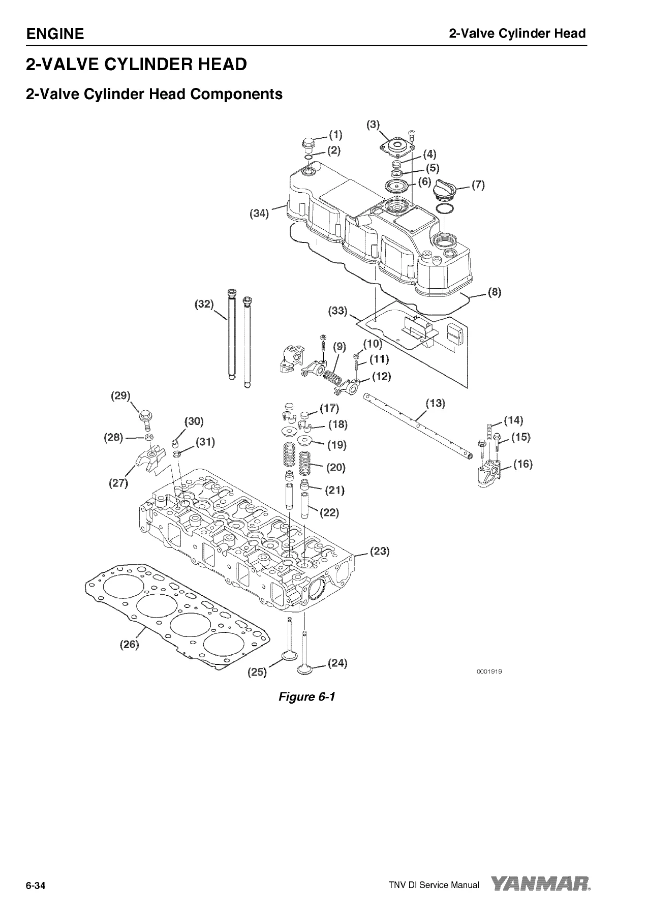
2-Valve Cylinder Head Components
Components of a two-valve cylinder head
Disassembly of 2-Valve Cylinder Head
Removing the glow plugs
Removal of Valve Cover
Removal of Rocker Arm Assembly
Disassembly of Rocker Arm Assembly
Removal of Cylinder Head
Removal of Intake / Exhaust Valves
Removal of Valve Guides
Cleaning of Cylinder Head Components
Inspection of Cylinder Head Components
Inspection of Push Rods
Inspection of Rocker Arm Assembly
Inspection of Valve Guides
Inspection of Cylinder Head
Inspection of Intake and Exhaust Valves
Inspection of Valve Springs
Reassembly of Cylinder Head
Reassembly of Valve Guides
Reassembly of Intake and Exhaust Valves
Reassembly of Cylinder Head
Reassembly of Rocker Arm Reassembly
Reassembly of the Valve Cover
4-Valve Cylinder Head
4-Valve Cylinder Head Components
Disassembly of 4-Valve Cylinder Head
Removal of Valve Cover
Removal of Rocker Arm Assembly
Disassembly of Rocker Arm Assembly
Removal of Cylinder Head
Removal of Intake and Exhaust Valves
Removal of Valve Guides
Cleaning of Cylinder Head Components
Inspection of Cylinder Head Components
Inspection of Push Rods
Inspection of Rocker Arm Assembly
Inspection of Valve Guides
Inspection of Cylinder Head
Inspection of Intake and Exhaust Valves
Inspection of Valve Springs
Inspection of Valve Bridges
Reassembly of Cylinder Head
Reassembly of Valve Guides
Reassembly of Intake and Exhaust Valves
Reassembly of Cylinder Head
Reassembly of Rocker Arm Assembly
Reassembly of the Valve Cover
Measuring and Adjusting Valve Clearance
2-Valve Cylinder Heads
4-Valve Cylinder Heads
Crankshaft and Camshaft Components
Disassembly of Engine
Disassembly of Camshaft and Timing Components
Removal of Timing Gear Case Cover
Checking Timing Gear Backlash
Measuring Idler Gear-to-Crankshaft Gear Backlash
Measuring Idler Gear-to-Camshaft Gear Backlash
Removal of Timing Gears
Removal of Oil Pan
Removal of Camshaft
Removal of Gear Case or Front Plate
Disassembly of Crankshaft and Piston Components
Removal of Pistons
Removal of Crankshaft
Inspection of Crankshaft and Camshaft Components
Replacement of Crankshaft Oil Seals
Measure Crankshaft Bearing Oil Clearance
Inspection of Cylinder Block
Inspection of Pistons, Piston Rings and Wrist Pin
Inspection of Connecting Rod
Inspection of Tappets
Inspection of Crankshaft
Inspection of Camshaft
Inspection of Camshaft Bushing and Bores
Inspection of Idler Gear and Shaft
Honing and Boring
Reassembly of Crankshaft and Piston Components
Reassembly of Pistons
Installation of Crankshaft
Installation of Pistons
Reassembly of Camshaft and Timing Components
Installation of Gear Case or Front Plate
Installation of Camshaft
Installation of Timing Gears
Installation of Gear Case Cover
Installation of Oil Pan
Final Reassembly of Engine
EGR system
EGR system
EGR system
4TNV98-E, 4TNV98-Z
4TNV84T-Z, 4TNV98T-Z
Inspecting/cleaning EGR related components
EGR Valve
EGR valve operation checks
Cleaning the EGR valves
Lead valves
Precautions for installation
EGR cooler
EGR pipe and other connecting elbows
Installing EGR related components/parts
Fuel System
Before You Begin Servicing
Introduction
Fuel Injection Pump
Stop Solenoid
Cold Start Device
Trochoid Fuel Pump
Electronically controlled governor
Fuel System Specifications
Special Torque Chart
Test and Adjustment Specifications
Special Service Tools
Measuring Instruments
Fuel System Diagram
Fuel System Components
2-Valve Cylinder Head
4-Valve Cylinder Head
Fuel Injection Pump
Removal of Fuel Injection Pump
Installation of Fuel Injection Pump
Checking and Adjusting Fuel Injection Timing
Determining the Fuel Injection Timing Specification
(6.8 X 2) = 13.6 + 4 = 17.6˚ Fuel injection Timing
Checking Fuel Injection Timing
Adjusting Fuel Injection Timing
Fuel Injectors
Removal of Fuel Injectors
2-Valve Cylinder Head
4-Valve Cylinder Head
Testing of Fuel Injectors
Disassembly and Inspection of Fuel Injectors
Adjusting Fuel Injector Pressure
Reassembly of Fuel Injectors
Installation of the Fuel Injectors
2-Valve Cylinder Head
4-Valve Cylinder Head
Fuel injection system (for a four-valve cylinder head)
Cooling System
Before You Begin Servicing
Introduction
Cooling System Diagram
Engine Coolant Pump Components
Engine Coolant System Check
Engine Coolant Pump
Removal of Engine Coolant Pump
Disassembly of Engine Coolant Pump
Cleaning and Inspection
Temperature Switch
Water temperature sensor
Thermostat
Radiator Cap
Reassembly of Engine Coolant Pump
Installation of Engine Coolant Pump
Lubrication System
Before You Begin Servicing
Introduction
Oil Pump Service Information
Lubrication System Diagram
Checking Engine Oil Pressure
Trochoid Oil Pump
3TNV82A to 4TNV88 Oil Pump Components
Disassembly of Oil Pump
Cleaning and Inspection
Check Outer Rotor Outside Clearance
Outer Rotor to Inner Rotor Tip Clearance
Check Outer Rotor Side Clearance
Check Inner Rotor and Gear Boss Clearance
Reassembly of Oil Pump
Trochoid Oil Pump
3TNV82A-B, 3TNV88-B, 3TNV88- U, 4TNV88-B4TNV88-U, 3TNV84T-Z, 4TNV84T-Z Oil Pump Components
Disassembly of Oil Pump
Cleaning and inspection
Check Outer Rotor Outside Clearance
Outer Rotor to Inner Rotor Tip Clearance
Check Outer Rotor Side Clearance
Check Rotor Shaft Clearance
Reassembly of Oil Pump
Trochoid Oil Pump
4TNV94L/98/106 Oil Pump Components
Disassembly of Oil Pump
Cleaning and Inspection
Check Outer Rotor Outside Clearance
Outer Rotor to Inner Rotor Tip Clearance
Check Outer Rotor Side Clearance
Check Rotor Shaft Clearance
Reassembly of Oil Pump
Turbocharger
Before You Begin Servicing
Introduction
Specifications
Turbocharger Service Information
Troubleshooting
Excessive Exhaust Smoke
Generates White Smoke
Sudden Oil Decrease
Decrease in Output
Poor (Slow) Response (Starting) of Turbocharger
Abnormal Sound or Vibration
Turbocharger Components
Turbocharger Component Functions
Theory of Operation
Turbine
Compressor
Bearings
Compressor Side Sealing Mechanism
Waste Gate Modulation
Waste Gate Control
Washing Procedure
Periodic Inspection
Visual Inspection
Inspection of Rotor Rotation
Inspection of Rotor Play
Removal of Turbocharger
Checking Rotor Play
To Check Rotor End Play:
To Check Rotor Run-out:
Waste Gate Valve Test
Waste Gate Actuator Leak Test
Installation of Turbocharger
Starter Motor
Before You Begin Servicing
Introduction
Starter Motor Information
3TNV82A to 4TNV88 – Standard and Optional
Starter Motor Specifications
Starter Motor Troubleshooting
Starter Motor Components
Starter Motor
Removal of Starter Motor
Disassembly of Starter Motor
Cleaning and Inspection
Armature
Field Coil
Magnetic Switch
Pinion Clutch Assembly
Reassembly of Starter Motor
Check Pinion Projection Length
No-Load Test
Installation of Starter Motor
Alternator
Before You Begin Servicing
Introduction
Dynamo and Alternator Information
3TNV82A to 4TNV106T – Standard and Optional Dynamos
3TNV82A to 4TNV106T – Standard and Optional Alternators
Alternator Specifications
Dynamo Specifications
Alternator Troubleshooting
Alternator Components
Alternator Wiring Diagram
Alternator Standard Output
Alternator
Removal of Alternator
Disassembly of Alternator
Reassembly of Alternator
Installation of Alternator
Dynamo Component Location
Dynamo Wiring Diagram
Operation of Dynamo
Dynamo Standard Output
Testing of Dynamo
Testing Stator Coil Continuity
Testing Stator Coil Short-to-Ground
Testing Dynamo Regulated Output
Dynamo
Removal of Dynamo
Disassembly of Dynamo
Reassembly of Dynamo
Installation of Dynamo
ELECTRONIC CONTROL SYSTEM
Engines available with the electronic control system
Before You Begin Servicing
Introduction
ELECTRONIC CONTROL SYSTEM
Electronic control harness connections
Electric Wiring
Electric Wiring Precautions
Electrical Wire Resistance
Battery Cable Resistance
Electrical Wire Sizes – Voltage Drop
Conversion of AWG to European Standards
Failure Diagnosis
DTCs (Diagnostic Trouble Codes) General Description
DTC Code List
Description Items
Analog Input Related Failures
Rack position sensor
Accelerator sensor
Spare accelerator sensor (option)
Atmospheric pressure sensor (option)
ECU Temperature Sensor
Cooling water temperature sensor
SENSOR 5V
Power supply Voltage
Pulse Sensor Related Failures
Speed Sensor
Spare speed sensor (option)
Engine rotational speed
Contact Output Related Failures
Rack actuator Relay
Start Assist Relay
CSD solenoid valve
EGR valve
Contact Input Related Failures
Oil Pressure Related Failures
Battery Charge Related Failures
Water Temperature Switch
Air cleaner switch
Oil-Water Separator Switch
Actuators etc.
Rack actuator
Engine
E-ECU Internal Errors
CAN Communication
Immobilizer
Method and Procedure of Failure Diagnosis
Description Items
E-ECU Pin Layout Diagram
How to use the 2G eco-checker harness
Analog Input Related Failures
Rack position sensor
Accelerator sensor
Foot pedal
Spare Analog (Spare accelerator sensor, Atmospheric pressure sensor)
Pulse accelerator
ECU Temperature Sensor
Cooling water temperature sensor
SENSOR 5V
Pulse Sensor Related Failures
Speed Sensor
Spare speed sensor
Contact Output Related Failures
RACK ACTUATOR RELAY
START ASSIST RELAY
CSD Solenoid Valve Coil
EGR valve
Contact Input Related Failures
Actuator Related Failures
Rack actuator
ECU Internal and Communication Errors
ECU Internal Errors
Main relay
CAN Communication
Immobilizer
FAILURE INDICATOR LAMP FLASHING PATTERN
Using the Failure Indicator for Failure Diagnosis
Flashing Patterns of the Failure Indicator
Factor Analysis
2G-Type Eco-Governor Speed-Fluctuation Factor Analysis
Special Service Tools
Troubleshooting By Measuring Compression Pressure
Compression Pressure Measurement Method
Measured Value and Troubleshooting
Quick Reference Table For Troubleshooting
Failure Diagnostic List
Electrical Wiring
BACK COVER

Delivery

IMAGES PREVIEW

Yanmar TNV Series Diesel Engine Service Manual - 3TNV82A to 4TNV106T Repair PDF β€” PDF page 1 preview
Yanmar TNV Series Diesel Engine Service Manual - 3TNV82A to 4TNV106T Repair PDF β€” PDF page 44 preview
Yanmar TNV Series Diesel Engine Service Manual - 3TNV82A to 4TNV106T Repair PDF β€” PDF page 167 preview

This Yanmar TNV Series Service Manual is delivered as an instant PDF download. No shipping, no waiting. The file can be viewed on any computer, tablet, or smartphone, and pages can be printed for use in the workshop. Whether you are a professional diesel technician or a hands-on owner, this manual puts the complete service information for the TNV engine family at your fingertips.
Reviews

There are no reviews yet.

Be the first to review “Yanmar TNV Series Diesel Engine Service Manual – 3TNV82A to 4TNV106T Repair PDF”

What Our Customers Say

β˜…β˜…β˜…β˜…β˜… Live reviews from customers
Loading customer reviews...
0
    0
    Your Cart
    Your cart is emptyReturn to Shop
    πŸ›’
    Recently Purchased
    πŸ•’ verified order