YANMAR ViO12-2A EXCAVATOR SERVICE MANUAL – PDF DOWNLOAD
YANMAR VIO12-2A EXCAVATOR SERVICE MANUAL – PDF DOWNLOAD:
IMAGE PREVIEW:
YANMAR ViO12-2A EXCAVATOR SERVICE MANUAL – PDF DOWNLOADYANMAR ViO12-2A EXCAVATOR SERVICE MANUAL – PDF DOWNLOAD
DESCRIPTION:
YANMAR ViO12-2A EXCAVATOR SERVICE MANUAL – PDF DOWNLOAD
Correct work means the quickest possible completion of according to the correct procedures and the specified standards.
It is important when conducting certain operations always to bear in mind the equipment, tools, gauges, materials, oil and grease, etc. that you must have ready, as well as items to be checked, adjusted, or disassembled, and cautions to watch out for.
(1) Never attempt servicing while engine is running or immediately after stopping operation. (2) Wear work cloths, safety shoes and helmet. (3) Check the equipment and tools before use. Especially, be sure to check the crane, lifting equipment and tools.
(4) When working together with other persons, allocate everyone’s share of job, arrange the signals and act in concert with the other persons. (5) The operation of the crane and slinging work must be performed by qualified persons.
(6) Do not enter or pass under the raised load. (7) Lift and support the massive parts by crane before removing the installation bolts. (8) Disconnect cables from battery before repairing the electric system.
(9) Remove the battery when welding the machine. (1) Check the service record of the machine. (That is, check how many months or hours the machine has been used since the preceding overhaul, what was the trouble then and what parts were replaced.)
(2) Have all servicing tools ready, i.e., tools, measuring devices (which have received periodic maintenance), containers, oil & grease, etc. (3) Have the service literature (operation manual, parts catalog, etc.) ready.
(1) Clean the machine before disassembly. (2) Check and record the condition of the machine before disassembly : • Model, machine number, operation hours • Reasons for repair, history of repair •
Contamination of filters • Fuel and oil condition • Damage to parts, etc. (3) Place alignment marks on the necessary parts to facilitate reassembly. (4) Clean all the removed parts and new replacement parts and put them in order. (5) Use new seals, split pins, etc. for reassembly.
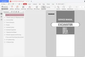
TABLE OF CONTENTS:
YANMAR ViO12-2A EXCAVATOR SERVICE MANUAL – PDF DOWNLOAD
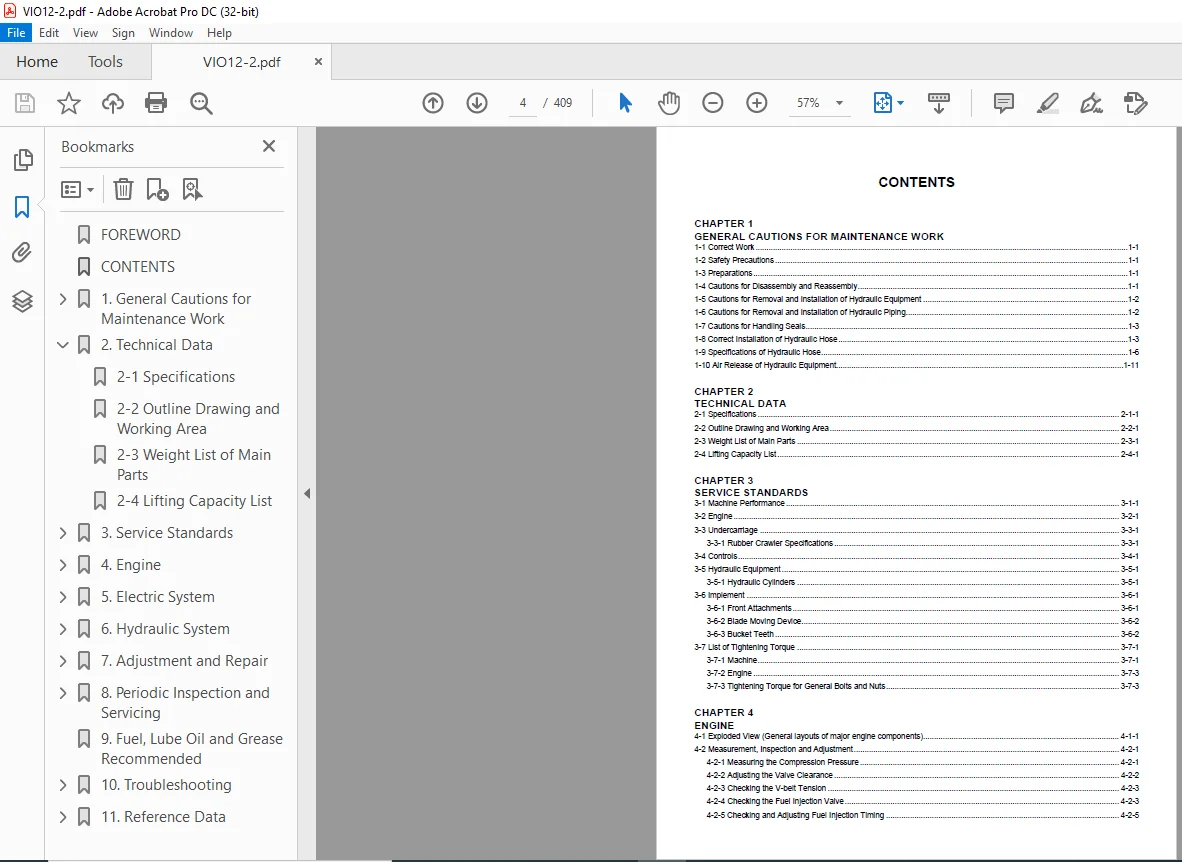
FOREWORD...................................................................................  2
CONTENTS...................................................................................  4
1. General Cautions for Maintenance Work...................................................  8
	1-1 Correct Work....................................................................... 10
	1-2 Safety Precautions................................................................. 10
	1-3 Preparations....................................................................... 10
	1-4 Cautions for Disassembly and Reassembly............................................ 10
	1-5 Cautions for Removal and Installation of Hydraulic Equipment....................... 11
	1-6 Cautions for Removal and Installation of Hydraulic Piping.......................... 11
	1-7 Cautions for Handling Seals........................................................ 12
	1-8 Correct Installation of Hydraulic Hose............................................. 12
	1-9 Specifications of Hydraulic Hose................................................... 15
	1-10 Air Release of Hydraulic Equipment................................................ 20
2. Technical Data.......................................................................... 22
	2-1 Specifications..................................................................... 24
	2-2 Outline Drawing and Working Area................................................... 32
	2-3 Weight List of Main Parts.......................................................... 33
	2-4 Lifting Capacity List.............................................................. 34
3. Service Standards....................................................................... 36
	3-1 Machine Performance................................................................ 38
	3-2 Engine............................................................................. 42
	3-3 Undercarriage...................................................................... 46
		3-3-1 Rubber Crawler Specifications................................................ 46
	3-4 Controls........................................................................... 48
	3-5 Hydraulic Equipment................................................................ 49
		3-5-1 Hydraulic Cylinders.......................................................... 49
	3-6 Implement.......................................................................... 50
		3-6-1 Front Attachments............................................................ 50
		3-6-2 Blade Moving Device.......................................................... 51
		3-6-3 Bucket Teeth................................................................. 51
	3-7 List of Tightening Torque.......................................................... 52
		3-7-1 Machine...................................................................... 52
		3-7-2 Engine....................................................................... 54
		3-7-3 Tightening Torque for General Bolts and Nuts................................. 54
4. Engine.................................................................................. 56
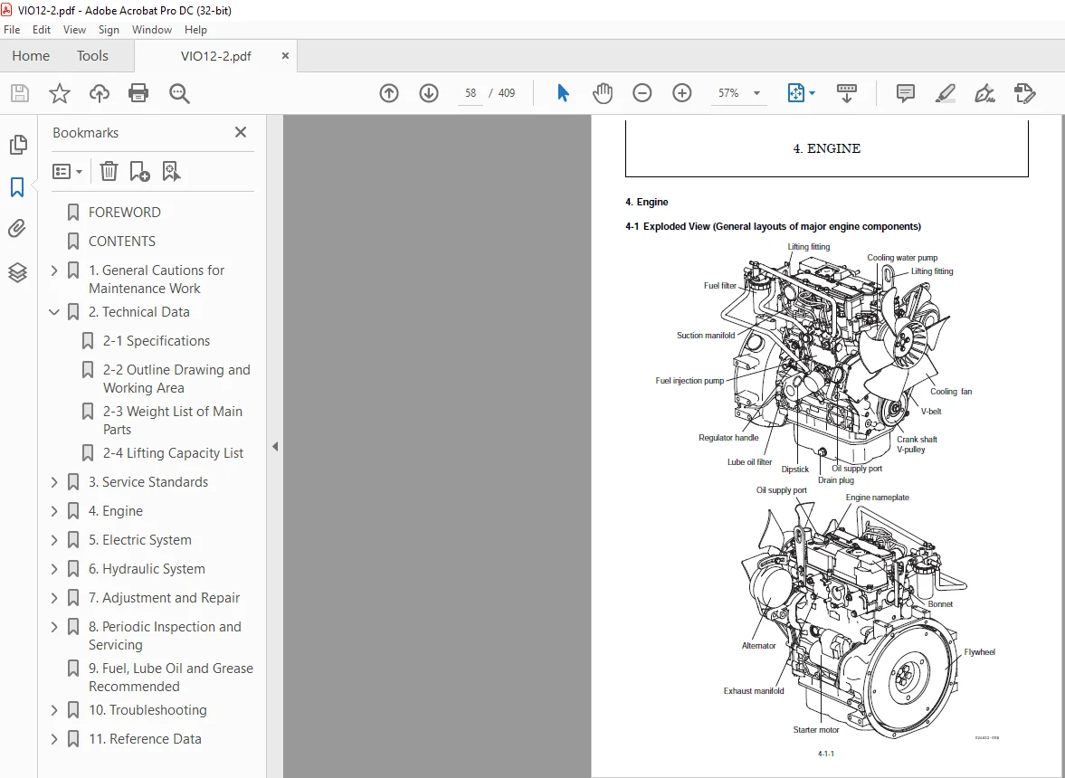
	4-1 Exploded View (General layouts of major engine components)......................... 58
	4-2 Measurement, Inspection and Adjustment............................................. 59
		4-2-1 Measuring the Compression Pressure........................................... 59
		4-2-2 Adjusting the Valve Clearance................................................ 60
		4-2-3 Checking the V-belt Tension.................................................. 61
		4-2-4 Checking the Fuel Injection Valve............................................ 61
		4-2-5 Checking and Adjusting Fuel Injection Timing................................. 63
		4-2-6 Adjusting the Maximum (or Minimum) Idling Speed.............................. 68
		4-2-7 Checking the Cooling Water System and Radiator for Water Leakage............. 68
		4-2-8 Checking the Sensors......................................................... 69
	4-3 Measurement Procedure, Service Data and Corrective Action.......................... 70
		4-3-1 Cylinder Head................................................................ 70
		4-3-2 Cylinder Block............................................................... 75
		4-3-3 Valve Rocker Arm............................................................. 77
		4-3-4 Piston and Piston Rings...................................................... 79
		4-3-5 Connecting Rod............................................................... 82
		4-3-6 Cam shaft.................................................................... 85
		4-3-7 Crank shaft.................................................................. 86
		4-3-8 Gears........................................................................ 89
		4-3-9 Trochoid Pump................................................................ 90
	4-4 Precautions for Reassembly......................................................... 91
	4-5 Electrical Equipment............................................................... 94
		4-5-1 Starter Motor................................................................ 94
		4-5-2 Alternator................................................................... 95
5. Electric System......................................................................... 98
	5-1 Parts Layout of Electrical Equipment...............................................100
		5-1-1 Electrical Equipment and Electric Wiring.....................................100
	5-2 Monitor and Alarm Systems..........................................................102
		5-2-1 Part Name....................................................................102
		5-2-2 Performances of Alarm Sensors................................................102
		5-2-3 Operation of Alarm Sensors...................................................103
		5-2-4 Inspection of Electrical Equipment...........................................104
	5-3 Wiring Diagram.....................................................................109
	5-4 Circuit Description of Engine Start and Stop 5-4-1 Start Engine....................110
		5-4-1 Start Engine.................................................................110
		5-4-2 Engine Stop..................................................................111
		5-4-3 Battery Charge...............................................................112
		5-4-4 Failure in Battery Charge....................................................112
6. Hydraulic System........................................................................113
	6-1 Outline............................................................................115
		6-1-1 Control Valve Operation......................................................120
	6-2 Hydraulic Circuit Schematic........................................................123
	6-3 Circuit Operation..................................................................124
		6-3-1 Boom.........................................................................124
		6-3-2 Arm..........................................................................128
		6-3-3 Bucket.......................................................................132
		6-3-4 Swing........................................................................136
		6-3-5 Boom Swing...................................................................140
		6-3-6 Blade........................................................................144
		6-3-7 Travel.......................................................................148
		6-3-8 Track Gauge Change...........................................................152
		6-3-9 Simultaneous Operation of Travel and Blade...................................156
		6-3-10 Simultaneous Operation of Boom Up and Bucket................................160
		6-3-11 Hydraulic P.T.O.............................................................164
		6-3-12  Safety Lock................................................................167
	6-4 Pressure Adjustment................................................................170
		6-4-1 System Relief Valves.........................................................170
		6-4-2 Circuit Relief Valves........................................................171
		6-4-3 Swing Brake Valve............................................................172
		6-4-4 Cut-Off Valve................................................................173
	6-5 Hydraulic Pump.....................................................................174
	6-6 Control Valve......................................................................192
	6-7 Pilot Valve........................................................................212
	6-8 Cut-off Valve......................................................................221
	6-9 Swing Motor........................................................................227
	6-10 Travel Motor......................................................................244
	6-11 Solenoid Valve....................................................................271
7. Adjustment and Repair...................................................................276
	7-1 Engine of machine..................................................................277
		7-1-1 Removal and Reinstallation of Engine.........................................277
		7-1-2 Removal and Reinstallation of Starter Motor..................................284
		7-1-3 Removal and Reinstallation of Fuel Injection Pump............................287
		7-1-4 Removal and Reinstallation of Fuel Tank......................................289
		7-1-5 Removal and Reinstallation of Radiator.......................................291
	7-2 Undercarriage......................................................................293
		7-2-1 Outline......................................................................293
		7-2-2 Points of Reassembly.........................................................294
		7-2-3 Removal and Reinstallation of Crawler........................................296
		7-2-4 Disassembly and Reassembly of Idler..........................................297
		7-2-5 Disassembly and Reassembly of Track Roller...................................300
		7-2-6 Removal and Reinstallation of Track Gauge Change Cylinder....................303
	7-3 Controls...........................................................................307
		7-3-1 Control Train................................................................307
		7-3-2 Mechanical Control Linkage...................................................308
		7-3-3 Adjustment of Travel and Blade Levers........................................310
		7-3-4 Adjustment of Boom Swing and P.T.O. Pedals and P.T.O. Pedal Lock.............311
		7-3-5 Adjustment of Lock Lever Switch..............................................312
		7-3-6 Adjustment of Travel Lever Lock..............................................313
		7-3-7 Adjustment of Accelerator Lever..............................................314
	7-4 Swing Bearing......................................................................316
		7-4-1 Removal and Reinstallation of Swing Bearing..................................316
	7-5 Hydraulic Equipment................................................................318
		7-5-1 Removal and Reinstallation of Hydraulic Oil Tank.............................318
		7-5-2 Removal and Reinstallation of Control Valve..................................323
		7-5-3 Removal and Reinstallation of Swing Motor....................................326
		7-5-4 Removal and Reinstallation of Swivel Joint...................................328
		7-5-5 Disassembly and Reassembly of Swivel Joint...................................332
		7-5-6 Disassembly and Reassembly of Hydraulic Cylinders............................335
		7-5-7 Removal and Reinstallation of Boom Swing Cylinder............................339
		7-5-8 Removal and Reinstallation of Hydraulic Oil Tank.............................343
		7-5-9 Piping Layout................................................................343
	7-6 Implement..........................................................................352
		7-6-1 Removal and Reinstallation of Implement......................................352
8. Periodic Inspection and Servicing.......................................................360
	8-1 List of Periodic Inspection and Servicing..........................................362
9. Fuel, Lube Oil and Grease Recommended...................................................364
10. Troubleshooting........................................................................368
	10-1 Non-Breakdowns....................................................................370
		10-1-1 Natural Release of Bucket...................................................370
		10-1-2 Discontinuous Arm Movement..................................................370
		10-1-3 Drifting of Upperstructure on Quick Travel Operation........................371
		10-1-4 Thermal Shock of Travel Motor...............................................372
		10-1-5 Change of Blade Speed in Loaded Condition...................................373
		10-1-6 Time Lag on Travel Speed Switching..........................................374
		10-1-7 Fluctuation in Oil Level of Hydraulic Oil Tank Due to Temperature Change....375
	10-2 Troubleshooting...................................................................376
		10-2-1 Machine and Engine..........................................................376
		10-2-2 Electrical Equipment on Panel...............................................397
11. Reference Data.........................................................................406
	11-1 Specifications for Attachment.....................................................408
PLEASE NOTE:
This is not a physical manual but a digital manual – meaning no physical copy will be couriered to you. The manual can be yours in the next 2 mins as once you make the payment, you will be directed to the download page IMMEDIATELY.
This is the same manual used by the dealers inorder to diagnose your vehicle of its faults.
Require some other service manual or have any queries: please WRITE to us at [email protected]
SK
2 reviews for YANMAR ViO12-2A EXCAVATOR SERVICE MANUAL – PDF DOWNLOAD





Cal Kellen –
Good , No problems
Titus Briar –
Great access