
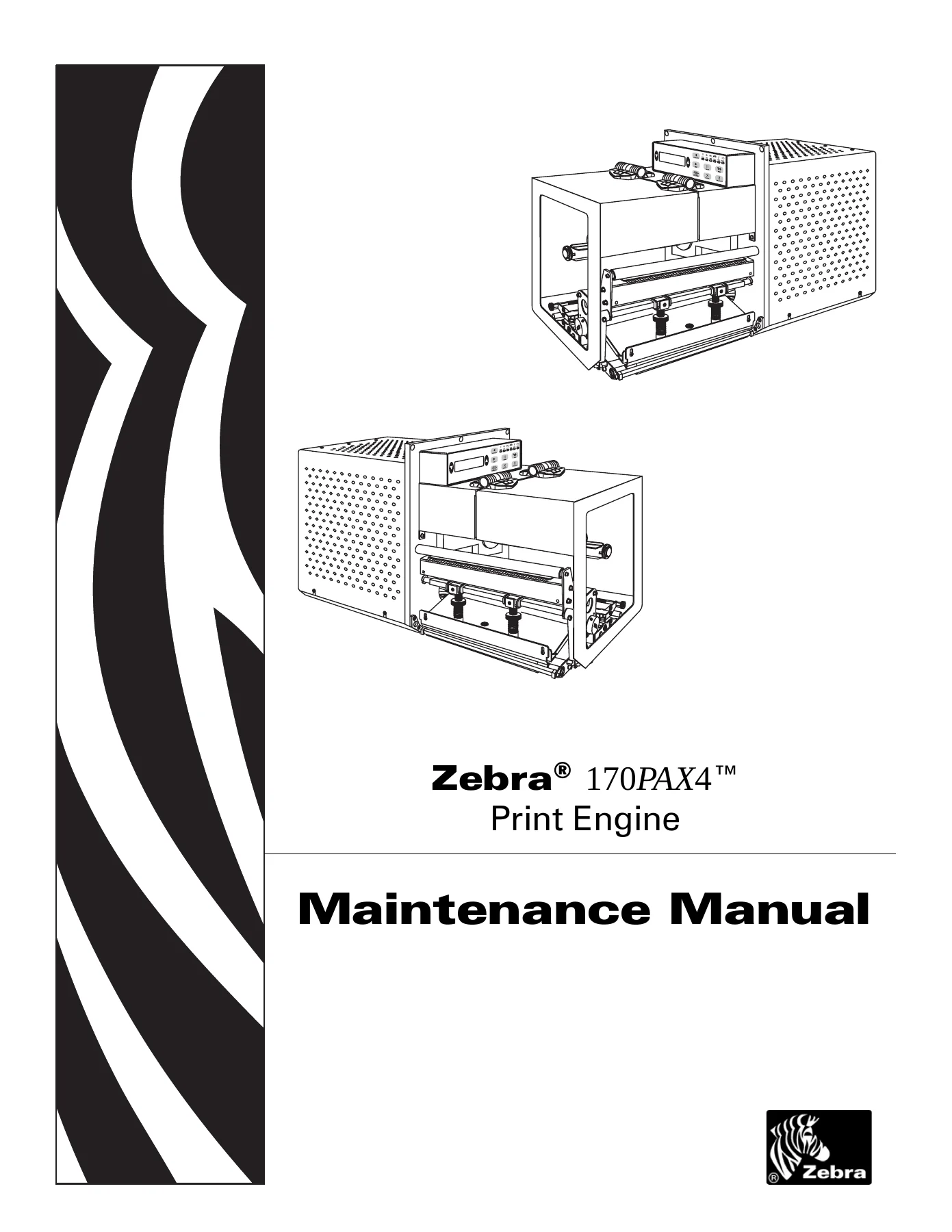
Zebra 170PAX4 Print Engine Maintenance Manual – Complete Service, Repair & Parts PDF
Original price was: $39.95.$24.95Current price is: $24.95.
The full Zebra 170PAX4 Print Engine Maintenance Manual in PDF – 396 pages of installation, setup, troubleshooting, printhead adjustment, exploded assembly drawings, parts lists, data port pinouts and cable specifications for right-hand and left-hand 203 dpi and 300 dpi print engines.
Description
The Zebra 170PAX4 Print Engine Maintenance Manual is the complete technical service guide for the 170PAX4 thermal transfer print engine, covering both the 203 dot/inch and 300 dot/inch versions in right-hand and left-hand configurations. Close to 400 pages long, it carries a technician from installation and media loading all the way through front panel configuration, fault diagnosis, and full teardown and rebuild of every major assembly. This is not an operator’s booklet – it is the bench reference you keep open when a print engine has to be brought back into specification.
File Details
- Manual type: Maintenance Manual (service, repair and preventive maintenance)
- Brand: Zebra Technologies Corporation
- Model: 170PAX4 Print Engine
- Customer order number: 57518L-001
- Revision: Rev. A
- Publication date: 3/18/05
- Language: English
- File format: PDF
Chapters Covered
- About This Document – who should use it, how it is organized, contacts and support, document conventions, related documents
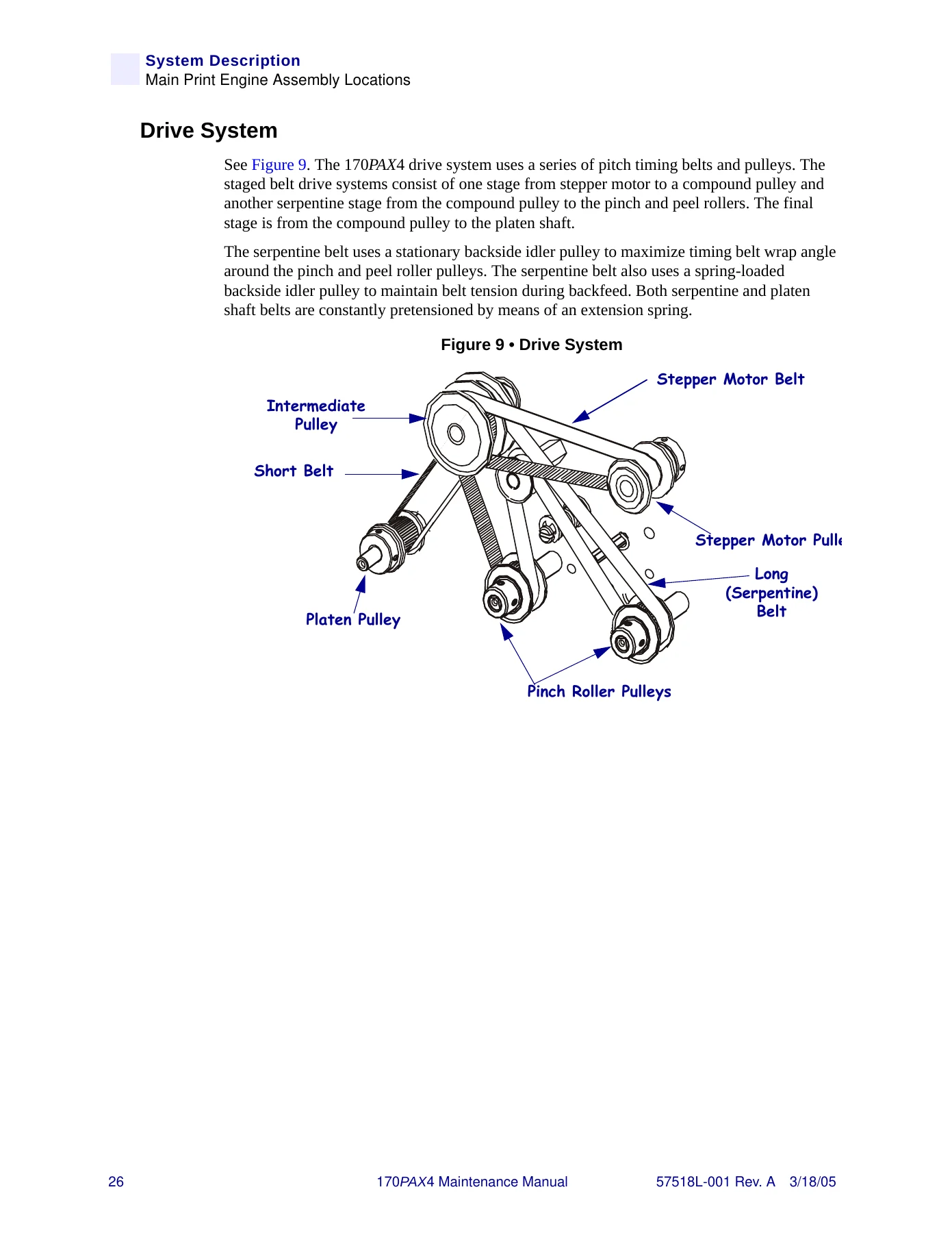
- System Description – exterior views of the print engine, front panel buttons and indicator LEDs, power on/off switch, physical, environmental and agency approvals data, electrical and communications specifications, memory, print engine options, printing specifications, media specifications, ribbon specifications, ZPL II, bar codes, standard font matrices, and the locations of the platen roller, peel roller assembly, DC and AC power supply assemblies, drive system, media sensor, peel bar and applicator interface board
- Operations – unpacking and inspection, installation requirements, mounting the print engine in an applicator, connecting to a power source and power cord specifications, selecting a communication interface, data cable requirements, types of media, loading media, ribbon selection and loading, removing used ribbon, adjusting the ribbon and media sensors, the Setup Mode overview, front panel LCD parameter displays, changing password-protected parameters, print server LCD displays, printing configuration and network configuration labels, and calibrating the print engine
- Troubleshooting – troubleshooting checklists, LCD error messages, memory errors, print quality problems, communications problems, miscellaneous print engine problems, Power-On Self Test, CANCEL Self Test, PAUSE Self Test, FEED Self Test, FEED and PAUSE Self Test, and the Communications Diagnostics Test
- Preventive and Corrective Maintenance – equipment safety tips, personal safety tips, tools required, the recommended preventive maintenance schedule, lubrication guidance, cleaning the exterior, cleaning the interior, cleaning the printhead and rollers, cleaning the peel bar and media path, spindle adjustment and maintenance, toggle positioning, print quality adjustments, printhead parallelism, balance, position and pressure adjustments, strip plate optimal adjustment, print darkness adjustment, tear-off position adjustment, power fuse replacement, and Routine Referral Procedures for every major assembly
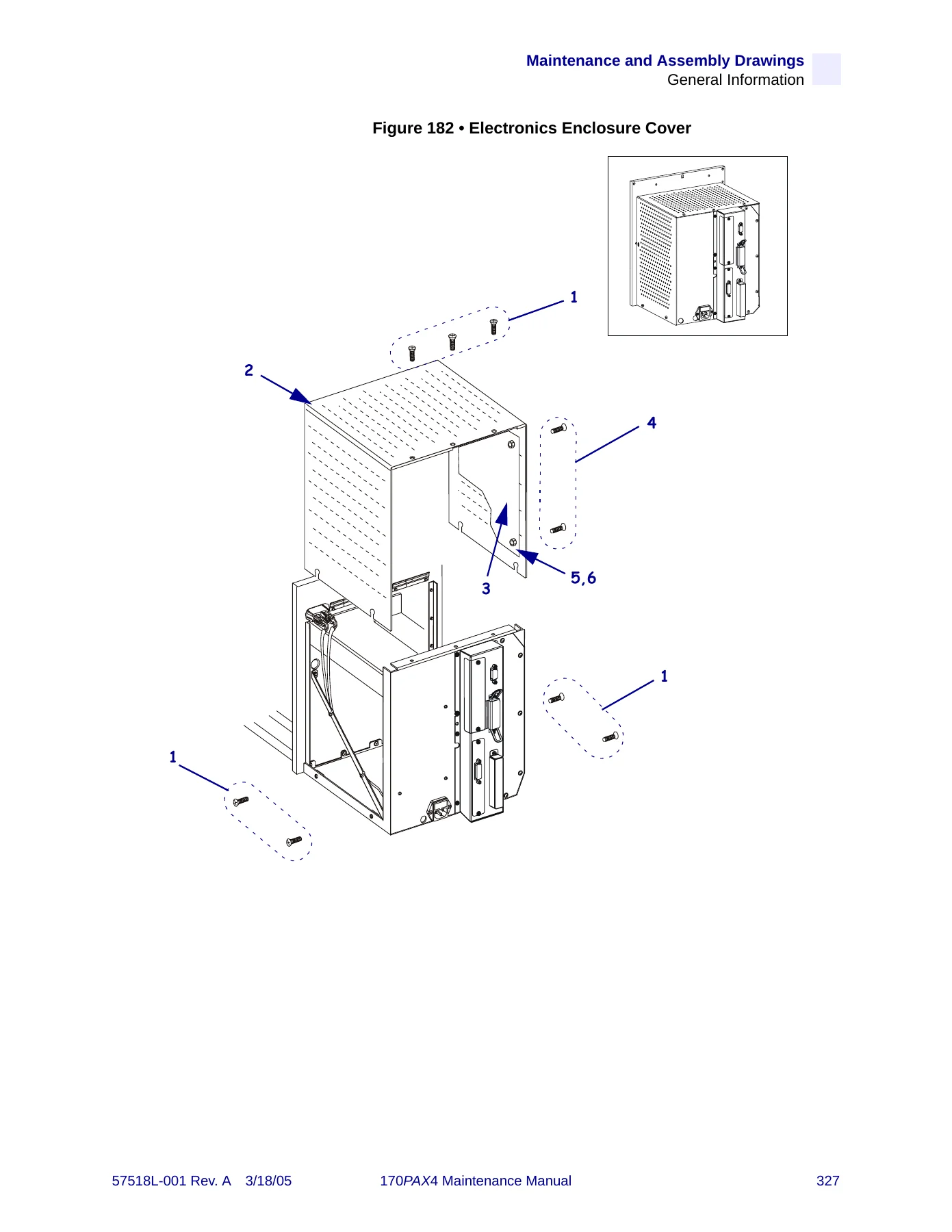
- Maintenance and Assembly Drawings – front cover, door-open switch, ribbon supply and take-up spindles, spindle gear cover, printhead, upper print mechanism, lower print mechanism, elastomer peel roller, platen roller, label guide shelf, segment roller and lower media sensor, top media sensor track, electronics enclosure cover, main logic board, applicator interface board and PCMCIA board, AC and DC power supply boards and control panel, pulleys and belts, intermediate pulley and stepper motor, gears and pulleys, ribbon supply and take-up gears and DC motors, power entry and ribbon tension control board, cable harnesses, and individual cables
- Data Ports – applicator interface connector, applicator signals, applicator interface connector pin configuration, jumper configurations for the +5 V I/O applicator interface board, parallel data port, parallel cabling requirements, parallel port interconnections, serial data port, hardware control signal descriptions, serial pin configuration, and RS-232 interface connections
- Cable Specifications – individual cable names, part numbers and termination locations for the right-hand and left-hand print engine
- Glossary and Index – common terminology plus a full index for fast lookups
Read end to end, the manual builds a complete picture of the 170PAX4 platform. The System Description chapter defines what each subassembly does and how the staged belt drive, platen roller, peel roller assembly and media sensor interact, which is what makes the later adjustment procedures make sense. The Operations chapter then establishes the correct baseline – media type, sensor type, print method, print width, maximum label length, ribbon tension, backfeed sequence, applicator port mode and the head resistor value – before a single label is produced. Everything after that assumes that baseline is right, which is exactly why having the real procedure matters.
What the Troubleshooting Chapter Actually Delivers
The troubleshooting coverage is organised as tables of symptom, probable cause and recommended action rather than vague advice. LCD error messages are broken out individually – ribbon out, ribbon in, paper out, head open, head too hot, head cold and the various memory errors – each with the conditions that trigger it and the corrective path. Print quality faults get their own table covering general quality issues, wrinkled ribbon, long tracks of missing print, fine angular grey lines on blank labels, light or missing printing on one side, printing that is too light or too dark across the whole label, smudge marks, misregistration and skipped labels, vertical drift in top-of-form position, and bar codes that will not scan. Communications problems and miscellaneous lock-ups are handled the same way, and the chapter closes with the diagnostic self tests so a technician can print a configuration label, a PAUSE test label or a communications diagnostic printout and read the result.
Corrective Maintenance and the Routine Referral Procedures
The corrective maintenance chapter is where the Zebra 170PAX4 Print Engine Maintenance Manual earns its place on the bench. It opens with the print quality adjustment sequence and explains that printhead parallelism, printhead balance, printhead position, printhead pressure and strip plate position are interrelated, so changing one can undo another. Each is then given its own step-by-step procedure with the adjustment screws identified, the direction of rotation spelled out, and the tolerance to aim for. From there the manual moves into the Routine Referral Procedures, which cover removing and opening the print engine, removing and reinstalling the PCB access panel, closing and reinstalling the unit in the applicator, replacing the printhead power cable, replacing the lower media sensor, installing a printhead, replacing the ribbon sensor, servicing the stepper motor, intermediate pulley and stepper motor pulley, replacing the peel roller, and swapping out the main logic board, PCMCIA board, wireless PCMCIA option board, ZebraNet 10/100 Print Server, applicator interface board, ribbon tension control board, cable harness, DC power supply, AC power supply, door-open switch and control panel.
Maintenance and Assembly Drawings
The drawings chapter works as a companion to the repair procedures. It pairs each assembly with an illustration and a parts table listing the item number, part number, description and quantity, and it separates right-hand from left-hand part numbers where they differ. Assemblies covered include the front cover, door-open switch, ribbon supply and take-up spindles, spindle gear cover, printhead, upper print mechanism in two sheets, lower print mechanism, elastomer peel roller, platen roller, label guide shelf, segment roller and lower media sensor, top media sensor track, electronics enclosure cover, main logic board with the applicator interface board and PCMCIA board, AC and DC power supply boards and control panel, pulleys and belts, intermediate pulley and stepper motor, gears and pulleys, ribbon supply and take-up gears and DC motors, power entry and ribbon tension control board, cable harnesses and cables. Parts shown in bold can be purchased individually; italicised items are listed for reference and may only be available as part of a maintenance kit – both conventions are explained at the start of the section.
Data Ports, Cable Specifications and the Applicator Interface
Because the 170PAX4 is normally mounted in an applicator rather than used stand-alone, the appendices carry a lot of practical weight. The Data Ports appendix documents the DB-15 applicator interface connector pin by pin for both the +5 V I/O and the +24-28 V versions, lists what each input and output does, shows the jumper configuration for isolated versus non-isolated operation, and includes timing diagrams for applicator modes 1 through 4. The parallel port pinout, serial port pinout, RS-232 connection diagram, DB-9 to DB-25 adapter wiring and modem connection wiring are all reproduced. The Cable Specifications appendix then lists every cable by part number with its from and to termination points, split into separate tables for the right-hand and left-hand print engines – which turns a vague wiring fault into a traceable path.
Get the Zebra 170PAX4 Print Engine Maintenance Manual
IMAGES PREVIEW
With this manual on hand you can install and configure a 170PAX4 correctly, load media and ribbon, calibrate the media and ribbon sensors, set the applicator port mode, work through an LCD error message to its actual cause, correct print quality faults by adjusting parallelism, balance, position and pressure in the right order, replace a printhead and set its resistor value, tear down the drive system, replace any of the circuit boards or power supplies, and reassemble the unit using the exploded drawings and parts tables. Getting these procedures right matters because an incorrectly set head resistor or a mis-sequenced printhead adjustment can shorten printhead life or damage the platen roller, and because a print engine that is out of calibration will keep producing unscannable bar codes no matter how many times the label format is re-sent. The manual is delivered as an instant PDF download after payment – no shipping and no waiting – and it opens on a laptop, tablet or phone in the workshop, or can be printed and kept beside the machine.
Reviews
There are no reviews yet.