ZF ERGOPOWER 4/6 WG-130/160 REPAIR INSTRUCTION MANUAL – PDF DOWNLOAD
$24.95
ZF ERGOPOWER 4/6 WG-130/160 REPAIR INSTRUCTION MANUAL – PDF DOWNLOAD
Description
ZF ERGOPOWER 4/6 WG-130/160 REPAIR INSTRUCTION MANUAL – PDF DOWNLOAD
FILE DETAILS:
ZF ERGOPOWER 4/6 WG-130/160 REPAIR INSTRUCTION MANUAL – PDF DOWNLOAD
Language : English
Pages : 96
Downloadable : Yes
File Type : PDF
IMAGES PREVIEW OF THE MANUAL:
TABLE OF CONTENTS:
ZF ERGOPOWER 4/6 WG-130/160 REPAIR INSTRUCTION MANUAL – PDF DOWNLOAD
ZF – ERGOPOWER 4/6 WG-130/160 0
Preface 65
General Information 9
Denomination of Standard Dimensions 11
Conversion Table 12
Torque Limit ZF Standard 148 13
Technical Data 4 WG 130/160 38
Technical Data 6 WG 160 41
Repair Instruction 1-2 0
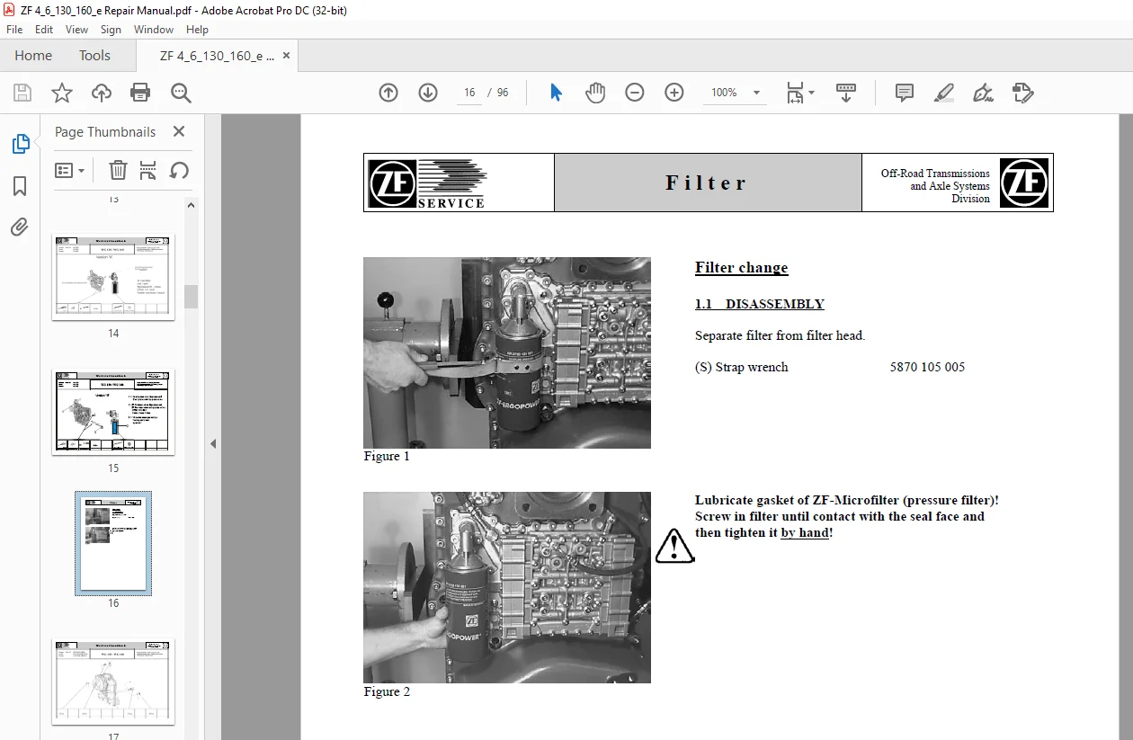
1 Filter change 0
1 1 Tools and Torque limits 15
1 1 1 Version A 14
1 1 2 Version B 15
2 Inductive sensors 0
2 1 Tools and Torque Limits 17
3 Bypass- and relief valve 0
3 1 Tools and Torque Limits 19
4 Shift unit 0
4 1 Tools and Torque Limits 25
5 Lock-up valve 0
5 1 Tools and Torque Limits 29
6 Output shaft seals 0
6 1 Tools and Torque Limits 32
6 2 Testing Diff switch 36
7 Temp sensor 37
Tables 4 WG 130/160 47
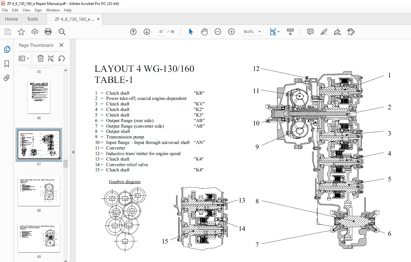
Layout 4 WG-130/160 47
Installation view direkt installation – Front view – 48
Installation view direkt installation Rear view – Standard version 49
Installation view direkt installation Rear view – with disk Brake – 50
Installation view separate installation – Front view – 51
Installation view separate installation Rear view – Standard version 52
Installation view separate installation Rear view – with disk Brake – 53
Schedule of measuring points and connections 54
Oil circuit diagram – Forward 1st speed – 56
Electro-hydraulic control with Proportional valves 58
Power flow 60
Fully automatic control EST-37 Circuit diagram – 6029 717 040 – 0
Controller DW-3 63
Controller ERGO II 64
Type plate 65
Tables 6 WG 160 66
Layout 6 WG-160 66
Installation view direct installation – Front view 67
Installation view direct installation – Rear view 68
Installation view separate installation with disk brake – Front view 69
Installation view separate installation with disk brake – Rear view 70
Installation view separate installation with axle disconnection and WK-valve -Front view 0
Installation view separate installation with axle disconnection and WK – Rear view 72
Schedule of measuring points and connections with ZF-fine filter directly mounted on the transmisson 73
Oil circuit diagram with ZF-fine filter directly mounted on the transmission – Forward 1st speed – 75
Schedule of measuring points and connections with externally mounted ZF-fine filter 77
Oil circuit diagram with externally mounted ZF-fine filter -Forward 1st speed – 79
Schedule of measuring points and connections with WK and externally mounted ZF-fine filter 81
Oil circuit diagram with WK and externally mounted ZF-fine filter – Forward 1st speed – 83
Gearbox diagram 85
Power flow – Forward speeds – 86
Power flow – Reverse speeds – 87
Electro-hydraulic shift control with proportional valves 88
Fully-automatic control unit EST-37 circuit diagram – Standard (6029 717 039) 90
Speed range selector DW-3 92
Controller VTS-3 93
Controller SG-6 94
Pushbutton switch D -7 95
Type plate 96
DESCRIPTION:
ZF ERGOPOWER 4/6 WG-130/160 REPAIR INSTRUCTION MANUAL – PDF DOWNLOAD
PREFACE:
This documentation has been developed for skilled staff trained by the ZF Passau for the repair and
maintenance works on ZF-units.
- Documented is a ZF-serial product representing the design state at the time of the edition.
- However, due to further technical developments of the product, the repair of the unit at your disposal could
require different steps as well as different adjustments and testing specifications. - Therefore, we recommend to commit your ZF-product to foremen and technicians whose practical and
theoretical training is permanently updated in our after-sales service school.
The service stations established world-wide by the Zahnradfabrik Friedrichshafen are offering to you:
1. Continuously trained staff
2. Prescribed facilities, e.g. special tools
3. Genuine ZF-spare parts meeting the latest state of development.
GENERAL:
- The Service Manual covers all works required for dismantling and the pertaining installation.
When repairing the transmission, ensure utmost cleanliness and that the works are carried out in an expertlike
manner. - The transmission should only be disassembled for renewing damaged parts. Covers and housing parts
installed with seals must be loosened by slight blows with a plastic mallet after screws and nuts have been
removed. For removing parts being in tight contact with the shaft such as antifriction bearings, bearing
races, and similar, use suitable pulling devices.
ZF ERGOPOWER 4/6 WG-130/160 REPAIR INSTRUCTION MANUAL – PDF DOWNLOAD:
S.V 2/04/2025