ZF ERGOPOWER 4/6 WG 260-310 Repair Instruction Manual – PDF DOWNLOAD
$17.95
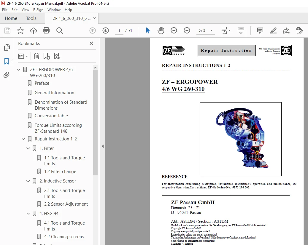
ZF ERGOPOWER 4/6 WG 260-310 Repair Instruction Manual – PDF DOWNLOAD
Description
ZF ERGOPOWER 4/6 WG 260-310 Repair Instruction Manual – PDF DOWNLOAD
FILE DETAILS:
ZF ERGOPOWER 4/6 WG 260-310 Repair Instruction Manual – PDF DOWNLOAD
Language : English
Pages : 71
Downloadable : Yes
File Type : PDF
IMAGES PREVIEW OF THE MANUAL:
TABLE OF CONTENTS:
ZF ERGOPOWER 4/6 WG 260-310 Repair Instruction Manual – PDF DOWNLOAD
ZF – ERGOPOWER 4/6 WG-260/310 0
Preface 2
General Information 3
Denomination of Standard Dimensions 5
Conversion Table 6
Torque Limits according ZF-Standard 148 7
Rapair Instruction 1-2 30
1 Filter 8
1 1 Tools and Torque limits 8
1 2 Filter change 9
2 Inductive Sensor 10
2 1 Tools and Torque limits 10
2 2 Sensor Adjustment 11
4 HSG 94 16
4 1 Tools and Torque limits 16
4 2 Cleaning screens 18
5 Lock up 21
5 1 Tools and Torque limits 21
5 2 Disassembly and Assembly 22
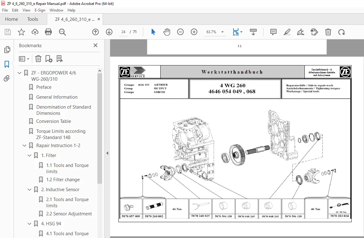
6 Output 24
6 1 Output “Standard” 24
6 2 Differential 25
6 3 Axle Disconnect 27
6 4 Crawler 26
7 Retarder 27
7 1 Tools and Torque limits 31
7 2 Retarder valve 32
Tables 4 WG 260/310 33
Layout 4 WG-260 33
Installation view direct mounting – Front view 34
Installation view separate installation – Front view 35
Installation view separate installtion – Side view 36
Installation view with 3rd and 4rd power take-off – Rear view 37
Installation view with 3rd and 4rd power take-off and emergency steering pump – Rear view 38
Installation view with disc brake – Rear view 39
Schedule of measuring points and connections 40
Oil circuit forward 1st speed 42
Electro-hydraulic control with proportional valves 44
Inductive transmitter and speed sensor (Hall sensor) 46
Fully automatic Control EST-37 circuit diagram Standard (6029 717 040) 47
Controller DW-3 49
Controller ERGO II 50
Tables 6 WG 260/310 51
Layout 6 WG-310 51
Installation view Retarder 10-o’clock position Front view 52
Installation view Retarder 10-o’clock position Side view 53
Installation view Retarder 10-o’clock position Rear view 55
Installation view Retarder 3-o’clock position Front view 56
Installation view Retarder 3-o’clock position Side view 57
Installation view Retarder 3-o’clock position Rear view 58
Schedule of measuring points and Connections 59
Oil circuit diagram – Forward 1st speed 62
Electrohydraulic control with Proportional valves 65
Fully-automatic Control EST-37 Circuit diagram – Standard (6029 717 039) 67
Controller VTS-3 69
Controller SG-6 70
Inductive transmitter and Speed sensor (Hallsensor) 71
S.V 08/24