ZF Ergopower Transmission 4 WG-190/210 Operator’s Manual PDF
$13.95
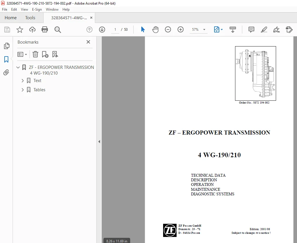
ZF Ergopower Transmission 4 WG-190/210 Operator’s Manual – PDF DOWNLOAD
Description
ZF Ergopower Transmission 4 WG-190/210 Operator’s Manual – PDF DOWNLOAD
FILE DETAILS:
ZF Ergopower Transmission 4 WG-190/210 Operator’s Manual – PDF DOWNLOAD
Language : English
Pages : 53
Downloadable : Yes
File Type : PDF
IMAGES PREVIEW OF THE MANUAL:
![]()
TABLE OF CONTENTS:
ZF Ergopower Transmission 4 WG-190/210 Operator’s Manual – PDF DOWNLOAD
Summary of the TECHNICAL DATA 6 – 7
IMPORTANT INSTRUCTIONS 9 – 10
I. DESCRIPTION 11
1.1 Function of the Converter
1.2 Powershift transmission
1.3 Transmission control
1.4 Controllers
1.4.1 General
1.4.2 Controller DW-3
1.4.3 Controller ERGO II
1.5 Display
1.5.1 General
1.5.2 Possible Indications on the Display
1.5.3 Error code definition
1.6 Electronic control unit TCU
1.7 Electronic control for the ZF-Powershift transmission
1.7.1 General
1.7.2 Description of the Basic functions
1.7.3 AEB
1.7.4 Downshifting functions (Down-Shift Button)
1.7.5 Pressure cut-off
1.7.6 Inching device
1.7.7 Special functions
II. INSTALLATION SPECIFICATION 25
III. OPERATION 27
3.1 Driving preparation and Maintenance
3.2 Driving and Shifting
3.3 Cold start
3.4 Transmission control in the Driving range Automatic
3.5 Stopping and Parking
3.6 Towing
3.7 Oil temperature
IV. MAINTENANCE 31
4.1 Oil grade
4.2 Oil level check replacement intervals
4.3 Oil change and Filter replacement intervals
4.3.1 Oil change and Oil filling capacity
4.3.2 Filter replacement
V. DIAGNOSTIC SYSTEMS 35
5.1 General
5.2 MOBIDIG 2001
5.3 Laptop Version
5.4 Multi-System 5000
ERGOPOWER
Off-Road Transmissions
and Axle Systems
Division
5
ANNEX, comprising:
Tables:
1 Layout 4 WG-190/210
Installation view 4 WG-190/120
2 Front view – Direct installation
3 Front view – Separate mounting
4 Rear view – Standard version
5 Rear view – With disc brake
6 Rear view – With 1. and 2. power take-off
7 Schedule of measuring points and connections 4 WG-190/210
8 Oil circuit diagram 4 WG-190/210 (Forward 1st speed)
9 Electro- hydraulic control with proportional valves
10 Power flow 4 WG-190/210 Forward/Reverse Speed
11 4 WG-190/210 Fully automatic control EST-37
Circuit diagram – 6029 717 040 –
12 Controller DW-3
13 Controller ERGO II
14 Type plate
S.V 08/24