ZF Transmission ZF-AS Tronic Bus Maintenance, Diagnosis, Component Replacement Repair Manual 1337751101b – PDF DOWNLOAD
$27.95
ZF Transmission ZF-AS Tronic Bus Maintenance, Diagnosis, Component Replacement Repair Manual 1337751101b – PDF DOWNLOAD
Description
ZF Transmission ZF-AS Tronic Bus Maintenance, Diagnosis, Component Replacement Repair Manual 1337751101b – PDF DOWNLOAD
FILE DETAILS:
ZF Transmission ZF-AS Tronic Bus Maintenance, Diagnosis, Component Replacement Repair Manual 1337751101b – PDF DOWNLOAD
Language : English
Pages : 128
Downloadable : Yes
File Type : PDF
IMAGES PREVIEW OF THE MANUAL:
![]()
![]()
![]()
DESCRIPTION:
ZF Transmission ZF-AS Tronic Bus Maintenance, Diagnosis, Component Replacement Repair Manual 1337751101b – PDF DOWNLOAD
Preface:
- This manual is intended for skilled personnel who have been trained by ZF Friedrichshafen AG to carry out
maintenance and repair work on ZF products. - This manual deals with the standard ZF product in accordance with the state of development on the date of
issue. - However, due to continuing development of the product, repair work might require work practices and test or
adjustment data which are not contained in this manual. - We therefore recommend that work done on your ZF
product is carried out only by skilled mechanics who have had their practical and theoretical knowledge updated on
a regular basis at our After-Sales Service training courses.
Service points equipped by ZF Friedrichshafen AG all over the world offer you:
1. Well-trained personnel
2. Specified equipment, e.g. specialized tools
3. Genuine ZF spares, to our latest specifications
- All work performed in these service points is carried out conscientiously and with care.
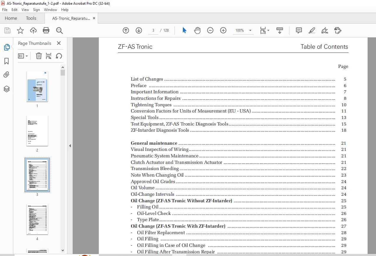
TABLE OF CONTENTS:
ZF Transmission ZF-AS Tronic Bus Maintenance, Diagnosis, Component Replacement Repair Manual 1337751101b – PDF DOWNLOAD
Repair Manual ZF-AS Tronic Bus..................................................  1
	Maintenance, Diagnosis,Component Replacement................................  1
	Repair Level 1 - 2..........................................................  1
	Copyright...................................................................  2
	Table of Contents...........................................................  3
	List of Changes: 1337 751 101...............................................  5
	Preface.....................................................................  6
	Safety Instructions.........................................................  7
	Instructions for Repairs....................................................  8
	Tightening torques.......................................................... 10
	Conversion Factors.......................................................... 11
	Special Tools............................................................... 13
	Diagnosis Tools............................................................. 15
	ZF-Intarder Diagnosis Tools................................................. 18
Maintenance..................................................................... 21
	General Maintenance......................................................... 21
	Visual Inspection of Wiring................................................. 21
	Pneumatic System Maintenance................................................ 21
	Clutch Actuator and Transmission Actuator................................... 21
	Transmission Bleeding....................................................... 22
	For oil changes, please note the following.................................. 23
	Approved Oil Grades......................................................... 24
	Oil Volume.................................................................. 24
	Oil-Change Intervals........................................................ 24
	Oil fill quantities ZF-AS Tronic Bus........................................ 24
	Oil Change (ZF-AS Tronic Without ZF-Intarder)............................... 25
		Filling Oil............................................................. 25
		Oil-Level Check(ZF-AS Tronic Without ZF-Intarder)....................... 26
		Type Plate.............................................................. 26
	Oil Change (ZF-AS Tronic With ZF-Intarder).................................. 27
		Oil Filter Replacement.................................................. 28
		Oil Filling (ZF-AS Tronic With ZF-Intarder)............................. 29
		Oil Filling in Case of Oil Change....................................... 29
		Oil Filling After Transmission Repair................................... 29
		Oil-Level Check (ZF-AS Tronic With ZF-Intarder)......................... 30
	Visual Inspection........................................................... 30
	Engine Coolant.............................................................. 31
	ZF-Intarder Type Plate...................................................... 31
Diagnosis....................................................................... 32
	Diagnosis on Vehicles with ZF Display and ZF Range Selector................. 32
	Diagnosis With Testman pro.................................................. 33
	Data Sheet: 20-pin Transmission Actuator.................................... 34
	Pin Assignment.............................................................. 35
	Data Sheet: 18-pin transmission actuator.................................... 36
Transmission Actuator........................................................... 37
	Removing Transmission Actuator.............................................. 37
	Removing the Upper Section from the Lower Section........................... 39
	Reattaching the Upper Section to the Lower Section.......................... 39
	Mounting Transmission Actuator.............................................. 40
	Replacing Pressure Relief Valve............................................. 43
	Programming Transmission Actuator........................................... 44
Clutch Actuator................................................................. 45
	Removing Clutch Actuator.................................................... 45
	Clutch Actuator Maintenance................................................. 46
	Bleeding and Assembling Clutch Actuator..................................... 47
	Replace Clutch.............................................................. 49
Clutch Release Mechanism........................................................ 50
	Removing Release Fork....................................................... 50
		Version A: Release fork with cams....................................... 50
		Version B: Release fork with cam rollers................................ 51
	Mounting Release Fork....................................................... 52
		Version A: Clutch release mechanism with cams........................... 52
		Version B: Release fork with cam rollers................................ 53
Output Flange................................................................... 55
	Removing the Output Flange.................................................. 55
	Mounting the Output Flange.................................................. 55
	Removing the Yoke........................................................... 56
	Mounting the Yoke........................................................... 56
Output Cover.................................................................... 57
	Removing the Output Cover................................................... 57
	Mounting the Output Cover................................................... 57
Impulse sensor.................................................................. 58
	Output impulse sensor (speed sensor)........................................ 58
	Remove impulse sensor....................................................... 58
	Fit impulse sensor.......................................................... 58
	Connector Replacement....................................................... 58
Neutral switch.................................................................. 59
	Replacing Neutral Switch.................................................... 59
	Remove Neutral switch....................................................... 59
	Install Neutral switch...................................................... 59
Intarder........................................................................ 60
	Replace Intarder Components................................................. 60
	Output Speed Sensor......................................................... 60
	Speedo Sensor............................................................... 60
	Solenoid Valve.............................................................. 60
	Temperature Sensor.......................................................... 60
	Removing 3/2 Directional Valve (accumulator charge valve)................... 61
	Mounting 3/2 Directional Valve.............................................. 61
	Removing Intarder Cable Harness............................................. 61
	Mounting Intarder Cable Harness............................................. 61
Additional Cooling.............................................................. 62
	Assembling the Valve Block of the Additional Cooling Unit................... 62
ZF Display...................................................................... 63
	Removal..................................................................... 63
	Installation................................................................ 63
	Wiring Diagram.............................................................. 63
	Connector Assignment........................................................ 63
	Connector Replacement....................................................... 63
Range selector.................................................................. 64
	Console-type range selector................................................. 64
		Removal................................................................. 64
		Installation............................................................ 64
		Connector Replacement................................................... 64
	Steering-column switch...................................................... 65
		Removal................................................................. 65
		Installation............................................................ 65
		Connector Replacement................................................... 65
	Pushbutton Range Selector................................................... 66
		Removal................................................................. 66
		Installation............................................................ 66
		Connector Replacement................................................... 66
	ZF Lever-Type Range Selector................................................ 68
Electronic Control Unit......................................................... 69
	E-module.................................................................... 69
		Removal................................................................. 69
		Installation............................................................ 69
		Connector Replacement................................................... 69
	E-module 2.................................................................. 70
		Removal................................................................. 70
		Installation............................................................ 70
		Connector Replacement................................................... 70
	ZMTEC....................................................................... 71
		Removal................................................................. 71
		Installation............................................................ 71
		Connector Replacement................................................... 71
		ZMTEC pin assignment.................................................... 72
Wiring.......................................................................... 73
	Type Designations and Order Numbers......................................... 73
Pneumatic Diagram............................................................... 74
Annex........................................................................... 75
	Attached Documents.......................................................... 75
		1337 754 101 - ZF-AS Tronic............................................. 76
			How to display and delete error memory.............................. 76
		1337 754 105 - ZF-AS Tronic............................................. 77
			ZF range selector keypad: How to display and delete error memory.... 77
		CAN BUS Measurements With Digital Multimeter............................ 78
		Checklist AS Tronic / AS Tronic mid..................................... 79
		Checklist AS Tronic 2 / AS Tronic mid North America..................... 84
		Programming Instruction for Testman Pro................................. 88
		SERVICE INFORMATION Nr. 26_05........................................... 93
		SERVICE INFORMATION Nr. 08_06c.......................................... 97
	Attached Drawings........................................................... 75
		0501 210 854d...........................................................103
		0501 211 185a...........................................................104
		0501 211 422e...........................................................105
		0501 320 211............................................................106
		6041 322 045d...........................................................107
		6041 622 023d...........................................................108
		1327 600 007i...........................................................109
		1328 600 019............................................................110
		1328 600 043............................................................111
		6006 629 024............................................................112
		6006 700 579c...........................................................113
		6006 700 586a...........................................................114
		0501 214 599............................................................115
		6029 713 148a...........................................................116
			Blatt 2.............................................................117
		6006 639 003a...........................................................118
		6029 713 149............................................................119
			Blatt 2.............................................................120
		6029 713 168............................................................121
			Blatt 2.............................................................122
		6029 711 038a...........................................................123
		6029 713 025b...........................................................124
			Blatt 2.............................................................125
Contact us: [email protected]
https://vimeo.com/874344919?share=copy
PLEASE NOTE:
- This is the SAME MANUAL used by the dealerships to diagnose your vehicle
- No waiting for couriers / posts as this is a PDF manual and you can download it within 2 minutes time once you make the payment.
- Your payment is all safe and the delivery of the manual is INSTANT – You will be taken to the DOWNLOAD PAGE.
- So have no hesitations whatsoever and write to us about any queries you may have : heydownloadss @gmail.com
S.V