Trusted Business
Verified & Licensed
Virus Free Files
100% Safe Downloads
Secure Payment
SSL Protected
Instant Delivery
Available Immediately
ZF Transmission ZF Reversing Gear 6 WG-200 Operation & Maintenance Manual 5872176002 – PDF DOWNLOAD
$20.95
ZF Transmission ZF Reversing Gear 6 WG-200 Operation & Maintenance Manual 5872176002 – PDF DOWNLOAD@
Instant PDF Download
Available immediately
Save to Your Device
Download & keep forever
Antivirus Scanned
100% virus-free
Trusted Worldwide
175,000+ customers
Description
ZF Transmission ZF Reversing Gear 6 WG-200 Operation & Maintenance Manual 5872176002 – PDF DOWNLOAD
FILE DETAILS:
ZF Transmission ZF Reversing Gear 6 WG-200 Operation & Maintenance Manual 5872176002 – PDF DOWNLOAD
Language : English
Pages : 87
Downloadable : Yes
File Type : PDF
IMAGES PREVIEW OF THE MANUAL:
![]()
![]()
![]()
TABLE OF CONTENTS:
ZF Transmission ZF Reversing Gear 6 WG-200 Operation & Maintenance Manual 5872176002 – PDF DOWNLOAD
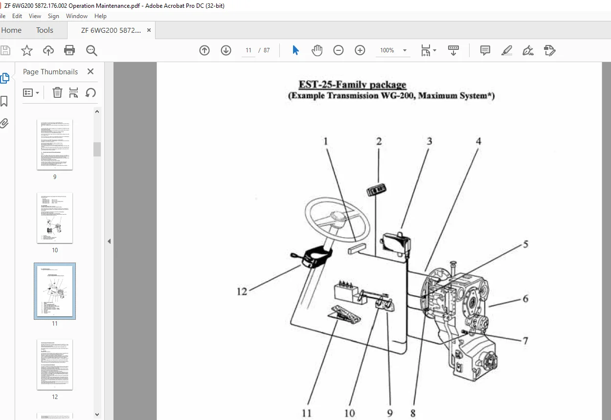
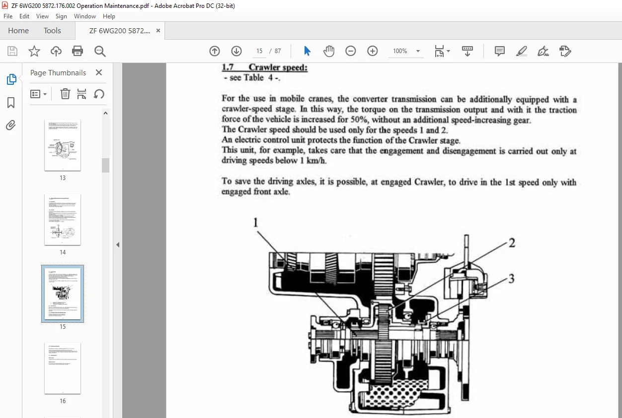
ZF - REVERSING GEAR 6 WG-200......................................................................................................... 1
	Text............................................................................................................................. 1
		Technical Data............................................................................................................... 2
		Important Instructions....................................................................................................... 4
		1. DESCRIPTION............................................................................................................... 5
			1.1 Function of the Converter............................................................................................ 5
			1.2 Powershift transmission.............................................................................................. 6
			1.3 Transmission control................................................................................................. 6
			1.4 Electronic control units for ZF-Powershift transmissions............................................................. 9
				1.4.1 Power-shift....................................................................................................10
				1.4.2 EST-Family - Package...........................................................................................11
			1.5 Retarder.............................................................................................................12
				1.5.1 Layout and function of the Retarder............................................................................12
			1.6 Interaxle differential (Length-compensating differential)............................................................14
				1.6.1 Description....................................................................................................14
				1.6.2 Function.......................................................................................................14
			1.7 Crawler speed........................................................................................................15
			1.8 Power take-offs......................................................................................................15
			1.9 Transmission output and Complementary units..........................................................................15
			1.10 Emergency steering pump.............................................................................................16
			1.11 Speedometer drive...................................................................................................16
		II. INSTALLATION INSTRUCTIONS................................................................................................17
		III. OPERATION...............................................................................................................19
			3.1 Driving preparation and Maintenance..................................................................................19
			3.2 Driving and Shifting.................................................................................................19
			3.3 Transmission control with electronic automatic unit..................................................................20
			3.4 Control of the transmission output and the various Complementary units...............................................21
			3.5 Stopping and Parking.................................................................................................22
			3.6 Towing...............................................................................................................22
			3.7 Oil temperature......................................................................................................22
		IV. MAINTENANCE..............................................................................................................23
			4.1 Transmission 6 WG-200................................................................................................ 0
				4.1.1 Oil quality.................................................................................................... 0
				4.1.2 Oil-level check................................................................................................ 0
				4.1.3 Oil change and Oil filling capacity............................................................................24
				4.1.4 Filter replacement.............................................................................................24
			4.2 Axle drives DK 7.....................................................................................................24
				4.2.1 Oil quality....................................................................................................24
				4.2.2 Oil-level check................................................................................................25
				4.2.3 Oil change ....................................................................................................25
			4.3 Axle drive APG-8/HK..................................................................................................26
				4.3.1 Oil quality.................................................................................................... 0
				4.3.2 Oil-level check................................................................................................ 0
				4.3.3 Oil change on the Axle drive...................................................................................26
	Tables...........................................................................................................................27
		Layout 6 WG-200 with axle declutch...........................................................................................27
		Layout 6 WG-200 with interaxle differential..................................................................................28
		Retarder 6 WG-200............................................................................................................29
		Crawler speed 6 WG-200.......................................................................................................30
		Interaxle differential 6 WG-200..............................................................................................31
		Axle drive DK-7 flange mounted on 6 WG-200...................................................................................32
		Axle drive APG-8/HK flange-mounted on 6 WG-200...............................................................................33
		Installation view 6 WG-200 center distance 400 mm - Front view...............................................................34
		Installation view 6 WG-200 center distance 400 mm - Side view................................................................35
		Installation view 6 WG-200 center distance 400 mm - Rear view................................................................36
		Installation view 6 WG-200 center distance 500 mm - Front view...............................................................37
		Installation view 6 WG-200 center distance 500 mm - Side view................................................................38
		Installation view 6 WG-200 center distance 500 mm - Rear view................................................................39
		Installation view 6 WG-200 direct mounting center distance 555 mm - Front view...............................................40
		Installation view 6 WG-200 direct mounting center distance 555 mm - Side view................................................41
		Installation view 6 WG-200 direct mounting center distance 555 mm - Rear view................................................42
		Installation view 6 WG-200 separate installation center distance 555 mm - Front view.........................................43
		Installation view 6 WG-200 separate installation center distance 555 mm - Side view..........................................44
		Installation view 6 WG-200 separate installation center distance 555 mm - Rear view..........................................45
		Installation view 6 WG-200 shift control lower position center distance 555 mm - Front view..................................46
		Installation view 6 WG-200 shift control lower position center distance 555 mm - Side view...................................47
		Installation view 6 WG-200 shift control lower position center distance 555 mm - Rear view...................................48
		Installation view 6 WG-200 with Retarder center distance 555 mm - Front view.................................................49
		Installation view 6 WG-200 with Retarder center distance 555 mm - Side view..................................................50
		Installation view 6 WG-200 with Retarder center distance 555 mm - Rear view..................................................51
		Installation view 6 WG-200 with axle drive APG-8/HK center distance 555 mm - Front view......................................52
		Installation view 6 WG-200 with axle drive APG-8/HK center distance 555 mm - Side view.......................................53
		Installation view 6 WG-200 with axle drive APG-8/HK center distance 555 mm - Rear view.......................................54
		Installation view 6 WG-200 with axle drive DK-7 and crawler speed center distance 555 mm - Front view........................55
		Installation view 6 WG-200 with axle drive DK-7 and crawler speed center distance 555 mm - Side view.........................56
		Installation view 6 WG-200 with axle drive DK-7 and crawler speed center distance 555 mm - Rear view.........................57
		Schedule of measuring points 6 WG-200 with Aluminum die-casting shift control, WK-valve and variovalve.......................58
		Schedule of measuring points 6 WG-200 with Aluminum die-casting shift control and WK-valve...................................59
		Schedule of measuring points 6 WG-200 with Aluminum die-casting shift control, WK-valve, variovalve and Retarder.............60
		Schedule of measuring points 6 WG-200 with Aluminum die-casting shift control, WK-valve and Retarder.........................62
		Oil circulation diagram 6 WG-200 with electric shift control 2-stage bleeder valve, variovalve and WK-Neutral................64
		Oil circulation diagram with electric shift control and WK - Neutral.........................................................65
		Oil circulation diagram 6 WG-200 with electric shift control 2-stage bleeder valve, variovalve, WK and Retarder - Neutral....66
		Oil circulation diagram 6 WG-200 with electric shift control and WK-Neutral..................................................67
		Aluminum die-cast shift control - 5-Magnet version with 2-stage, variovalve and WK...........................................68
		Aluminum die-cast shift control 5-Magnet version with WK.....................................................................69
		Power shift circuit diagram 6029 700 426 - sample - Dumper "Code H"..........................................................70
		Power shift connection diagram - 6029 700 428 - sample - Dumper "Code H".....................................................71
		Power shift connection diagram - 6029 700 616 - samplecrane vehicle "Code H".................................................72
		Semi- and fully automatic control circuit diagram - 6029 700 800 - sample dumper "Code H"....................................73
		Semi- and fully-automatic control connection diagram - 6029 700 789 - sample dumper "Code H".................................75
		Semi- and fully-automatic control circuit diagram - 6029 700 828 - sample crane vehicle "Code H".............................76
		Semi- and fully-automatic control connection diagram - 6029 700 836 - sample cran vehicle "Code H"...........................77
		Semi- and fully-automatic control circuit diagram controller - 6006 700 197..................................................78
		Inductive transmitter and electronic module..................................................................................79
		Tester PR-47  5870 221 147...................................................................................................80
		Tester PR-78 A  6008 001 001.................................................................................................81
		Summary PR-78................................................................................................................82
		Tester PR-78 A + B 5870 221 109..............................................................................................83
		Tester PR-78 A + B...........................................................................................................84
		Tester 5870 221 045..........................................................................................................85
		Dig. Measuring instrument  5870 221 129......................................................................................86
		Multi-System 5000 5870 221 250...............................................................................................87
Customer Support: [email protected]
PLEASE NOTE:
- This is the SAME MANUAL used by the dealerships to diagnose your vehicle
- No waiting for couriers / posts as this is a PDF manual and you can download it within 2 minutes time once you make the payment.
- Your payment is all safe and the delivery of the manual is INSTANT – You will be taken to the DOWNLOAD PAGE.
- So have no hesitations whatsoever and write to us about any queries you may have : heydownloadss @gmail.com
S.V