
14 Inch 50K Bucking Unit Service Manual – Farr Canada Hydraulic Power Tong & Backup PDF
Original price was: $34.95.$19.95Current price is: $19.95.
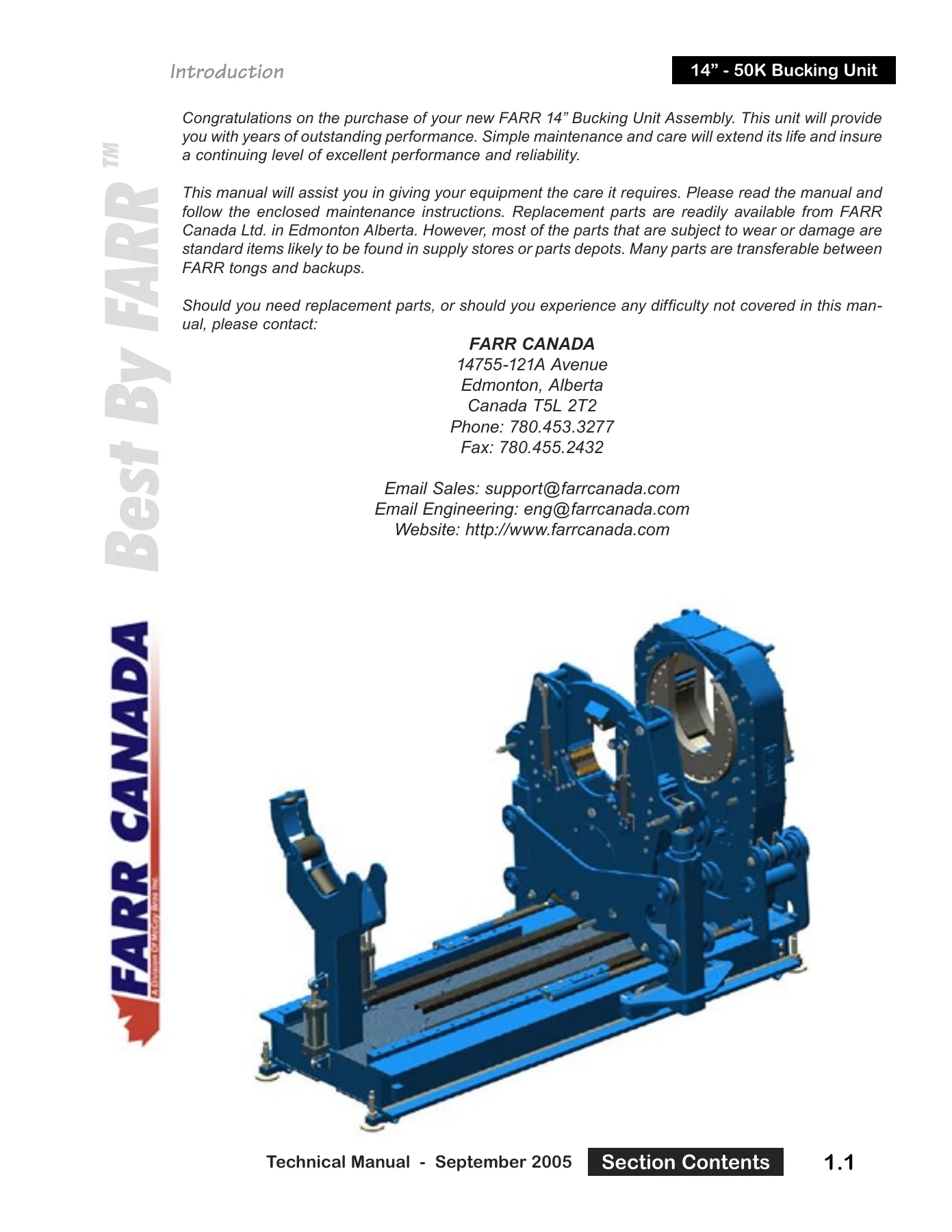
Complete 147-page Farr Canada technical manual for the 14″ – 50K Bucking Unit, covering the hydraulic power tong, backup, pipe roller stands, valve bank, WinCATT torque system, lubrication, overhaul and full exploded parts assemblies.
Description
File Details
- Manual type: Technical, service, maintenance and parts manual
- Brand: Farr Canada Ltd., Edmonton, Alberta, Canada
- Equipment covered: 14″ – 50K Bucking Unit (hydraulic power tong, backup, and pipe roller stands)
- Document date: October 2005, with Technical Manual – September 2005 section pages
- Language: English
- Page count: 147 pages
- File format: PDF
Chapters Covered
- Introduction and congratulations / Farr Canada contact information
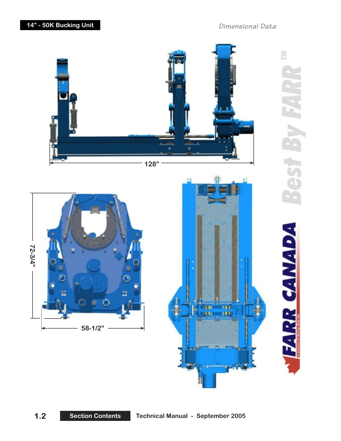
- Dimensional Views
- Specifications – Buckling Unit Specs
- Grease Specifications
- Hydraulic Fluid Specifications
- Tong Assembly – full assembly sequence
- Operation – Major Component Information
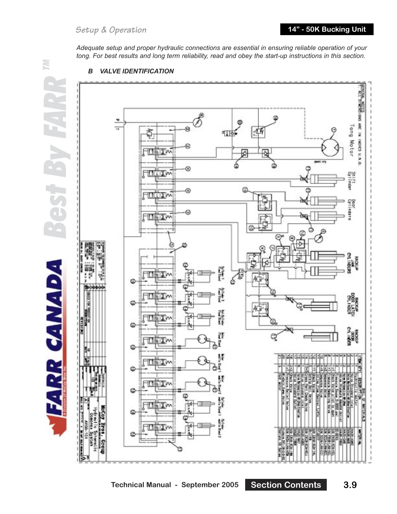
- Valve Identification
- Hydraulic Connections (parallel, series and series/parallel)
- WinCATT / Electrical Connections
- Jaw Installation
- Tong Operation
- Making / Breaking a Pipe Joint
- Maintenance – Cleaning, Lubrication, Adjustments
- Recommended Periodic Checks
- Overhaul Procedures
- Problem Diagnostics (pump noise, overheating, wear, slow tong, low torque, jaw grip failure, shifting faults)
- General Comments and cold weather operation procedures
- Storage Recommendations
- Assemblies and Parts – Geartrain Layout, Support Roller Assembly, Rotary Idler, Pinion Idler, Pinion Assembly, Clutch Assembly, Shifting Assembly, Tong Body Assembly, Load Cell Assembly, Frame Assembly, Tong Support Assembly, Backup Carriage Assembly, Return Spring Assembly, Motorized Remote Pipe Roller Stand, Pipe Roller Stand Lift Cylinder, Backup Body, Backup Body (Inside), Backup Door / Latch Assembly, Backup Door Cylinder Assembly
- Torque Gauge – parts list and service information
- Load Cell – parts list
- Troubleshooting and Periodic Inspection and Maintenance for the torque system
- Hydraulic Information – Hydraulic Motor Information (Rineer 37 Series, with repair manual) and Hydraulic Valve Information (DVA20 / DVA35 sections, seals and circuit descriptions)
For a crew running a 14″ – 50K Bucking Unit, this manual is the single reference that ties the whole package together. It opens with the dimensional envelope and full specification set, then walks through how the tong, backup, doors, wedge rams, shifting cylinder, pipe roller stands and WinCATT torque system are plumbed and controlled. Every hydraulic connection on the valve bank is identified valve-by-valve with its handle symbol and its effect on the machine, so an operator or technician can tell at a glance which lever closes the backup doors, which one compresses the rams, and which one is a proportional motor control. The maintenance chapter names each grease point on the tong by location and shows it photographically, and the overhaul chapter gives a step-by-step teardown sequence from load cell removal through top plate removal to expose the gear case. Behind all of that sits a complete parts section with exploded illustrations and Farr part numbers for the rotary gear, support rollers, idlers, pinion, clutch, shifting assembly, tong body, frame, backup body, door and latch, return spring, roller stand and lift cylinder, plus a separate torque gauge and load cell parts breakdown and the Rineer 37 Series motor and DVA valve documentation.
Specifications at a Glance
The specification pages list the working envelope of the unit: a torque range at 2,200 PSI of 12,000 ft-lb / 16,270 Nm in high gear and 50,000 ft-lb / 67,790 Nm in low gear, maximum 24 RPM in high gear at 50 GPM / 189 LPM and 5 RPM in low, hydraulic requirements up to 60 US GPM at 1,000 psi (227 LPM at 6.9 MPa) and 10 US GPM at 2,500 psi (38 LPM at 17.2 MPa), an overall length of 128″ / 3,251 mm, height of 72-3/4″ / 1,848 mm, width of 58-1/2″ / 1,486 mm, 10″ / 254 mm of space required on the pipe, a 37-1/2″ / 991 mm torque arm from pipe centreline to anchor centreline, and approximate weights of 6,500 lb / 2,955 kg for the mainframe assembly and 250 lb / 114 kg for the remote stand. Casing jaw sizes available run from 5-1/2″ through 14″. The grease and hydraulic fluid pages carry full performance requirements – NLGI grade 2 lithium complex grease data, oxidation and water washout limits, four ball and Timken test values, and the hydraulic fluid viscosity, pour point, flash point, filterability and pump-test approvals.
Valve Bank and Hydraulic Circuit Reference
A dedicated section identifies every control valve on the bank and matches it to the symbol printed on the control plate: the proportional tong motor valve, the two-way tong shift valve, the tong door valve, the sequenced backup valve, the fixed pipe roller stand gate, the stand height adjustment and stand motor valves, and the remote stand equivalents. It also covers the plumbing arrangements the operator can choose – three lift cylinders or three feed motors connected in parallel for independent control, connected in series so a single valve drives all three, or a hybrid setup where the lift cylinders stay independent while the feed motors run in series. On a large bucking unit this is the difference between a rig-up that runs smoothly and one that fights the operator all shift.
Setup, Pipe Centre, and Making or Breaking Joints
The operation chapter explains why pipe centre has to be set on the backup and the fixed stand before any joint is made, how the backup carriage adjustment nuts raise or lower the spring cylinder assembly, and how the threaded adjustment rod and stop on the stand set the working height – including jig and record-keeping methods for repeating the setting quickly. Step-by-step procedures for both making and breaking a joint are laid out in order, along with the rules that protect the gear train: completing the final turn of shouldered joints in low gear, and never using the snap break method. Cold weather procedures and the initial start-up and break-in routine are included as well.
Troubleshooting and Diagnostics
Separate diagnostic charts walk through excessive pump noise, hydraulic system overheating, excessive wear of moving parts, a tong running too slowly, a tong that will not develop sufficient torque, jaws that fail to grip pipe, and a tong that will not shift. Each entry pairs a possible problem with a solution. The torque system has its own troubleshooting table covering no gauge indication, readings that are too high or too low, and erratic or sluggish pointers, plus the recharge procedure for the load cell circuit.
Lubrication and Periodic Checks
Ten numbered lubrication points are identified and photographed – cage plate guide rings upper and lower, rotary roller bearings, rotary idler bearings, pinion idler bearings, pinion bearings, clutch shaft and motor gear bearings, the motor mount housing, the shifting shaft, door cylinder pivots and the backup return frame rollers – with recommended amounts at the completion of each job. The periodic check list covers the door stop spring, the shifting yoke jam nut and locknut, brake band adjustment, and torque gauge calibration against the tong arm length.
Parts, Exploded Assemblies and Documentation
The back half of the manual is a parts reference: exploded illustrations with item letters, descriptions, quantities and Farr part numbers for every major assembly, plus the tension torque gauge and load cell assembly with its 39″ torque arm and 60,000 ft-lb face, the gauge internals, the load cell internals, the Rineer 37 Series standard motor with performance data, model code and seal kits, and the DVA20 / DVA35 valve inlet, outlet and work section details with parallel section seals and circuit descriptions.
Get the Whole Machine Covered in One Download
Whether you are setting up the unit on a new location, diagnosing a torque problem, rebuilding the clutch or shifting assembly, replacing a door cylinder, chasing a failed seal in the wedge rams, or ordering the correct jaw for a casing size, this 14 Inch 50K Bucking Unit service manual puts the procedure, the specification and the part number in front of you. Working from the correct torque values, hydraulic pressures, lubrication points and assembly sequences is what keeps a bucking unit productive and keeps personnel safe around a machine that develops 50,000 ft-lb in low gear. The file is delivered instantly as a PDF after checkout – no shipping, no waiting, readable on any phone, tablet, laptop or desktop and printable for the shop or the rig floor.
IMAGES PREVIEW

Reviews
There are no reviews yet.