Description
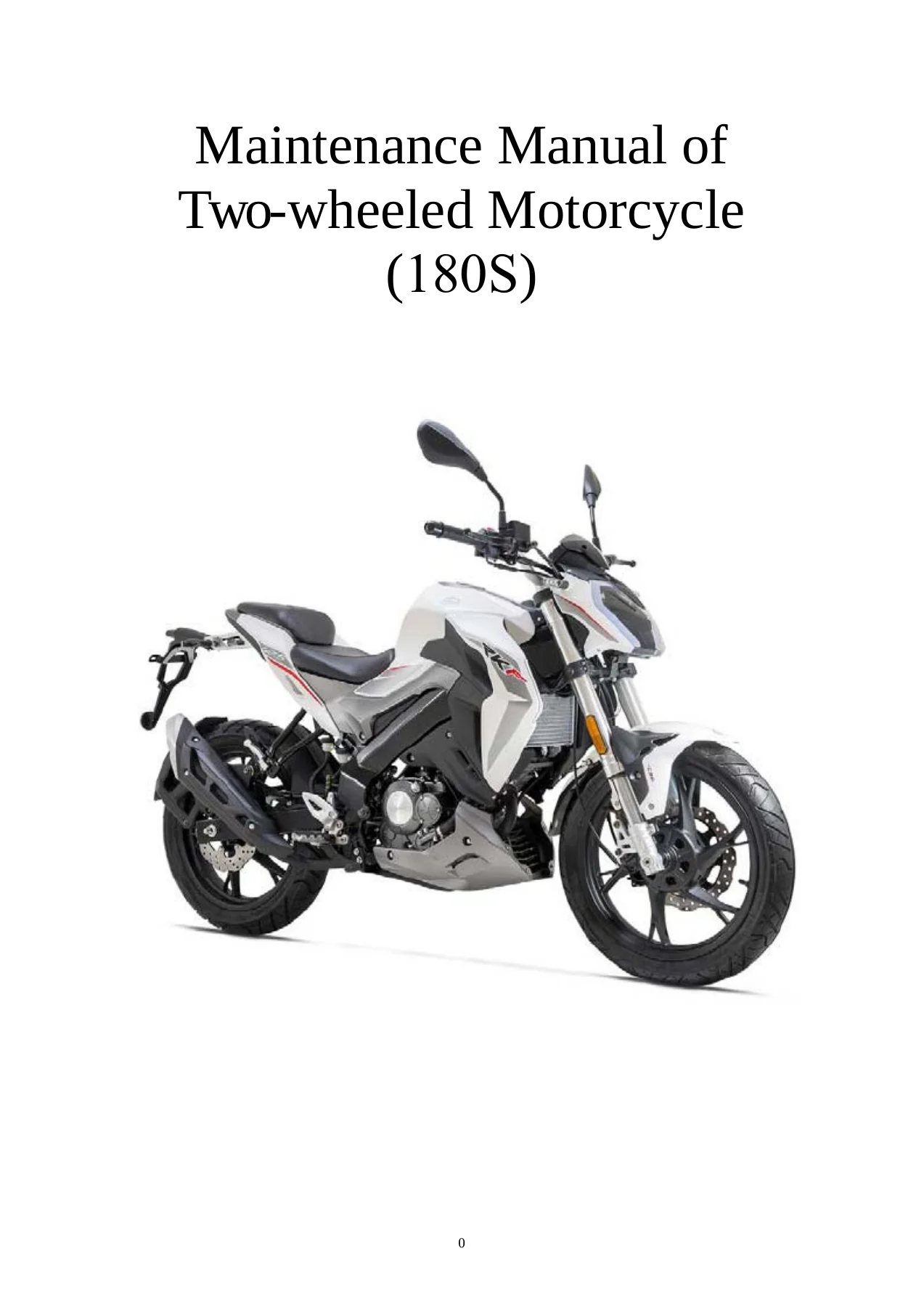
180S Two Wheeled Motorcycle Maintenance Manual – Your Complete Workshop Reference
This 180S Two Wheeled Motorcycle Maintenance Manual is the full English-language workshop document for the 180S platform, the motorcycle identified on its frame nameplate as a Zhejiang Qianjiang Motorcycle Co., Ltd. L3e-A1 machine and listed in the specification table as the RKF125. Across roughly 337 pages it walks a technician through every major assembly on the bike – from routine inspection and adjustment through engine teardown, brake hydraulics, the CBS combined braking system, cooling circuit, and the complete Delphi electronic fuel injection system with its OBD fault-code tables.
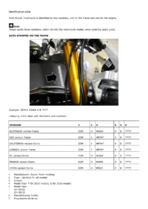
Unlike a generic motorcycle book, this is a machine-specific document. Frame numbers follow the LBBU3200?????????? pattern, engine numbers are stamped BJ154MI-4Aβ‘β‘β‘β‘β‘β‘β‘β‘, and the procedures, clearances, torque figures and exploded diagrams all belong to this single model. That specificity is exactly what makes a manual worth owning: the numbers in the tables are the numbers that apply to the bike in front of you.
File Details
- Manual type: Maintenance / Workshop Repair Manual
- Brand / Publisher: Zhejiang Qianjiang Motorcycle Co., Ltd.
- Model: 180S / RKF125 (L3e-A1)
- Engine: BJ154MI-4A
- Language: English
- Page count: Approx. 337 pages
- File format: PDF
- Document scope: Full motorcycle – engine, chassis, electrical, EFI, emission control, wiring diagram
Chapters Covered
The table of contents runs from general workshop safety all the way to a complete fold-out circuit diagram. The 180S Two Wheeled Motorcycle Maintenance Manual is organised into the following sections:
- Preface
- Preparatory Information – general safety, maintenance rules, motorcycle identification, important notes, special tools, specification table, fault diagnosis, inspection / adjustment
- Inspection and Maintenance of Electrical System – Battery / Charging System, Ignition System, Starter System, Bulbs / Switches / Instruments
- Inspection and Maintenance of Chassis – Brake, Body Cover, Front Wheel / Front Suspension, Rear Wheel / Rear Suspension, Fuel Tank / Seat, Disassembly / Installation of Engine
- Inspection and Maintenance of Engine – Lubrication System, Cylinder Head, Cylinder Block and Piston, Sub-assembly of Crankcase, Clutch, Cylinder Head Cover, Gearshift Mechanism, Drive System, Electric Starter, Cooling System, Exhaust Emission Control System, Electronic Injection System
- Circuit Diagram
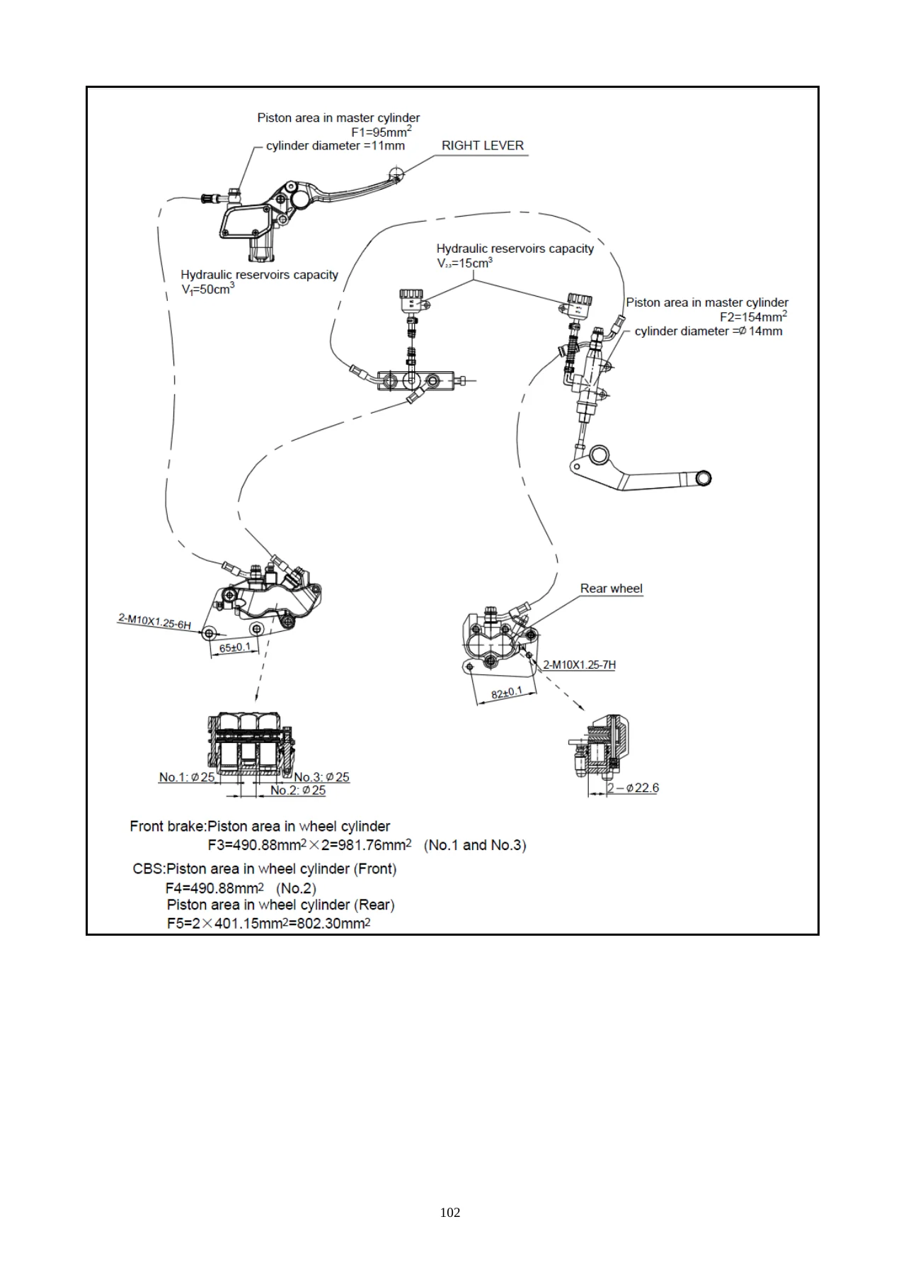
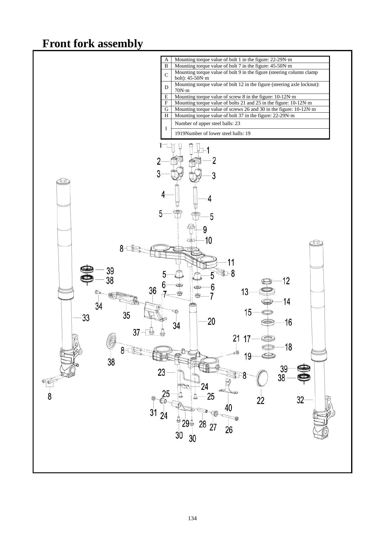
Underneath those headings the document drills down into the work a real workshop performs. The electrical chapter alone covers battery testing and charging, the charging system and voltage regulator, the alternator and charging coil, the trigger, ignition coil, spark plug and ECU, then the starter motor and starter relay, before moving into headlight, turn signal, tail light, meter, ignition switch and steering lock, horn and handlebar switch servicing. The chassis chapters handle front and rear brake discs, the CBS pump and combined braking circuit, body panels and covers, the front wheel and front fork, handlebar, front and rear shock absorbers, the rear wheel and rocker arm, chain drive, fuel tank and seat. The engine chapters take the motor apart properly – lubrication and fuel pump, cylinder head and valve train, cylinder block and piston, crankcase sub-assembly, clutch, cylinder head cover, gearshift mechanism, the primary and auxiliary shaft drive system, the electric starter, the pressurised cooling system with thermostat, radiator, water pump and coolant replacement, the exhaust emission control and catalyst conversion system, and finally the Delphi electronic injection system with its component-by-component testing and fault diagnosis routines.
What that adds up to is a document that supports the whole ownership cycle of the machine rather than a single job. A technician can use it to set valve clearance, measure cylinder bore for wear, check clutch plate thickness, bleed the combined brake system, adjust the drive chain, test an oxygen sensor, reset the idle speed stepper motor, or trace a no-spark fault through the ignition circuit. The fault diagnosis section near the front uses flow-chart style logic for common complaints – engine overheating, insufficient power, poor idle, high fuel consumption, clutch slip, difficult gear shifting, battery not charging, lights out – so even an intermittent problem can be narrowed down systematically rather than by guesswork.
Torque Values, Clearances and Specifications Included
One of the strongest reasons to keep this manual on the bench is the sheer volume of measured data it carries. The specification tables and the individual chapter sections supply the figures a mechanic needs to work to, including engine idle speed and spark plug gap, cylinder compression pressure, tyre pressures for both wheels, front and rear axle mounting nut torque, brake disc and brake pad wear limits, drive chain slackness, free stroke of the front brake lever and rear brake pedal, clutch cable free stroke, radiator hose clamp torque, coolant capacity and mixing ratio, engine oil capacity for a drain-and-refill versus a full disassembly, front fork oil quantity and viscosity, battery charging current and time, ignition coil and trigger impedances, and the full fault-code table for the MT05 engine controller. Rather than a scattered collection of numbers, these appear next to the procedure that needs them.
Who This Manual Suits
This 180S Two Wheeled Motorcycle Maintenance Manual is written for dealer-level maintenance, and it shows. The preface states plainly that it explains maintenance essentials for dealers, and the tool lists include special sockets, flywheel pullers, bearing removal and installation tools, oil seal replacers, piston pin pullers and piston ring clamps. That said, the step-by-step structure, the exploded diagrams and the specification tables make it equally usable by an experienced home mechanic who is prepared to buy or improvise the special tools, or by an independent workshop taking on a Qianjiang RKF125 for the first time. Anyone maintaining their own 180S will find the inspection and adjustment chapter alone justifies the download.
Why the Correct Procedures and Specifications Matter on This Machine
The 180S runs a four-valve, four-stroke single with electronic fuel injection, a three-way catalytic converter and an oxygen sensor in a closed-loop system. That combination is far less forgiving of guesswork than a carburetted machine. Valve clearance set outside the specified range affects intake manifold pressure and exhaust temperature, which in turn shortens the life of the oxygen sensor and catalyst. A combined braking system plumbed incorrectly or bled with the wrong fluid can leave the rider with degraded braking. Over-torquing a fuel pump mounting screw distorts the sealing washer and produces a leak. The manual gives the actual limits and the correct sequence for each of these jobs, which is precisely what separates a repair that lasts from one that comes back.
Complete PDF Bookmark Tree
Complete Bookmarks
The complete bookmarks in the β180S Two Wheeled Motorcycle Maintenance Manual – Qianjiang RKF125 Workshop Repair Guide PDFβ are as follows:
Contentsp. 2
Prefacep. 5
+Preparatory Informationp. 6
General safetyp. 6
Maintenance rulesp. 7
Motorcycle identificationp. 10
Important notesp. 10
Special toolsp. 11
Specification table (BJ125-31)p. 17
Fault diagnosisp. 19
+Inspection / adjustmentp. 44
Preparation standardp. 44
Regular maintenance checklistp. 47
Engine Oil/Filterp. 49
Inspection of cooling fluid levelp. 52
Inspection of radiator hosep. 53
Inspection/adjustment of throttle cablep. 53
Air filterp. 54
Spark plugp. 56
Batteryp. 57
Ignition timingp. 59
Cylinder pressurep. 59
Drive chain slacknessp. 60
Free stroke of front/rear brakep. 60
Inspection of brake fluid for leakagep. 62
Inspection of brakep. 64
Inspection of brake fluid levelp. 64
Inspection of wear of brake padp. 65
Inspection of CBSp. 65
Inspection of brake light switchp. 67
Headlightp. 67
Inspection/adjustment of clutch cablep. 68
Front/rear suspension systemp. 69
Bolt/nut/fixturep. 70
Tire specificationsp. 70
Rimp. 71
Steering column bearing and handlebar fixatorp. 72
Inspection and Maintenance of Electrical Systemp. 73
+I. Battery/Charging Systemp. 75
1.1 Preparatory Informationp. 75
1.2 Fault Diagnosisp. 76
1.3 Batteryp. 76
1.4 Charging Systemp. 78
1.5 Disassembly of Voltage and Current Regulatorp. 78
1.6 Alternator Charging Coilp. 79
1.7 Alternatorp. 80
+II. Ignition Systemp. 83
2.1 Preparatory Informationp. 83
2.2 Fault Diagnosisp. 85
+2.3 Triggerp. 86
2.3.1 Disassemblyp. 86
2.3.2 Inspectionp. 86
+2.4 Ignition Coilp. 86
2.4.1 Disassemblyp. 86
2.4.2 Inspectionp. 87
+2.5 Spark Plugp. 88
Inspection of spark plugp. 88
2.6 ECUp. 88
+III. Starter Systemp. 90
3.1 Preparatory Informationp. 90
3.2 Fault Diagnosisp. 90
+3.3 Starter Motorp. 91
3.3.1 Disassemblyp. 91
3.3.2 Installationp. 91
+3.4 Starter Relayp. 91
3.4.1 Disassemblyp. 91
3.4.2 Installationp. 91
+3.4.3 Inspectionp. 92
3.4.3.1 Operation Inspectionp. 92
3.4.3.2 Inspection of Voltage of Starter Relayp. 92
3.4.3.3 Inspection of Bond Strap Circuit of Starter Relayp. 93
3.4.3.4 Operation Inspectionp. 93
+IV. Bulbs /Switches/Instrumentsp. 95
4.1 Preparatory Informationp. 95
4.2 Fault Diagnosisp. 95
+4.3 Replacement of Headlight Bulbp. 96
4.3.1 Disassemblyp. 96
4.3.2 Installationp. 96
+4.4 Replacement of Front Turn Signal Lightp. 97
4.4.1 Disassemblyp. 97
4.4.2 Installationp. 97
+4.5 Replacement of Tail Lightp. 97
4.5.1 Disassemblyp. 97
4.5.2 Installationp. 97
+4.6 Meterp. 98
4.6.1 Disassemblyp. 98
4.6.2 Installationp. 99
+4.7 Ignition switch and steering lockp. 99
4.7.1 Inspectionp. 99
+4.7.2 Replacement of Ignition Switchp. 100
4.7.2.1 Disassemblyp. 100
4.7.2.2 Installationp. 100
+4.8 Electric hornp. 101
4.8.1 Disassemblyp. 101
4.8.2 Installationp. 101
4.8.3 Inspectionp. 101
4.9 Handlebar Switchp. 102
Inspection and Maintenance of Chassisp. 103
+V. Brakep. 108
5.1 Preparationp. 108
5.2 Fault Diagnosisp. 109
5.3 Front Brake Discp. 109
5.4 Rear Brake Discp. 111
+5.5 CBSp. 113
5.5.1 Replacement of brake hose and brake linep. 113
5.5.2 Adjustment of brake strokep. 114
+5.5.3 Front master cylinderp. 115
5.5.3.1 Disassembly of front master cylinderp. 115
5.5.3.2 Assembly of master cylinderp. 116
+5.5.4 Front caliperp. 117
5.5.4.1 Disassembly of front caliperp. 117
5.5.4.2 Inspection of brake shoep. 118
5.5.4.3 Assembly of front caliperp. 118
+5.5.5 Foot pump of rear brakep. 119
5.5.5.1 Disassembly of foot pump of rear brakep. 119
5.5.5.2 Assembly of rear foot pumpp. 120
+5.5.6 Rear Caliperp. 121
5.5.6.1 Disassembly of rear caliperp. 121
5.5.6.2 Inspection of brake shoep. 122
5.5.6.3 Assembly of rear caliperp. 122
+5.5.7 Assembly of CBS pumpp. 123
5.5.7.1 Assembly of CBS pumpp. 123
5.5.7.2 Assembly of CBS pumpp. 125
+5.5.8 Replacement and filling of brake fluidp. 125
5.5.8.1 Replacement and filling of front brake fluidp. 126
5.5.8.2 Replacement and filling of rear brake fluidp. 127
5.5.8.3 Replacement and filling of brake fluid of CBS pumpp. 128
VI. Body Coverp. 136
+VII. Front Wheel/Front Suspensionp. 141
7.1 Preparatory Informationp. 141
+7.2Fault Diagnosisp. 142
7.2.1 Turning Difficulty of Handlebarp. 142
7.2.2 Instability of Directionp. 142
7.2.3 Front Wheel Shimmyp. 142
7.2.4 Rotation Difficulty of Wheelp. 142
7.2.5 Abnormal Sound of Front Shock Absorberp. 142
+7.3 Front Wheelp. 142
7.3.1 Disassemblyp. 142
+7.3.2 Inspectionp. 143
7.3.2.1 Bending Inspection of Wheel Axlep. 143
7.3.2.2 Rim Shimmy Inspectionp. 144
7.3.2.3Inspection of Front Wheel Bearingp. 144
+7.3.3 Replacement of Bearingp. 144
7.3.3.1 Disassembly of Bearingp. 144
7.3.3.2 Inspection of Bearingp. 145
7.3.3.3 Installation of Bearingp. 145
7.3.4 Installationp. 145
+7.4 Handlebarp. 146
7.4.1 Disassemblyp. 146
7.4.2 Inspectionp. 148
7.4.3 Installationp. 148
+7.5 Front Forkp. 149
7.5.1 Disassemblyp. 149
7.5.2 Inspection of Steering Columnp. 152
7.5.3 Installationp. 153
+7.6 Front Shock Absorberp. 156
7.6.1 Replacement of Front Shock Absorberp. 156
7.6.2 Disassembly of Front Shock Absorberp. 160
+7.6.3 Inspectionp. 162
7.6.3.1 Inspection of Inner tube and Outer tubep. 162
7.6.3.2 Inspection of Dust Sealp. 162
7.6.3.3 Inspection of Spring Tensionp. 163
+VIII. Rear wheel/rear suspensionp. 167
8.1 Preparation of Information-p. 167
+8.2 Fault Diagnosisp. 167
8.2.1 Rear Wheel Shimmyp. 167
8.2.2 Inflexible rotation of wheelp. 167
8.2.3 Poor brake performancep. 168
8.2.4 Inflexible Brake Pedal or Slow Returnp. 168
+8.3 Rear Shock Absorberp. 168
8.3.1 Disassemblyp. 168
8.3.2Inspectionp. 169
8.3.3 Installationp. 169
+8.4 Rear Wheelp. 169
8.4.1 Disassemblyp. 169
+8.4.2 Inspectionp. 171
8.4.2.1 Bending Inspection of Wheel Axlep. 171
8.4.2.2 Rear Rim Shimmy Inspectionp. 171
8.4.2.3 Inspection of Rear Wheel Bearingp. 172
+8.4.3 Replacement of Bearingp. 172
8.4.3.1 Disassembly of Bearingp. 172
8.4.3.2 Inspection of Bearingp. 173
8.4.3.2 Installation of Bearingp. 173
8.4.4 Installationp. 173
+8.5 Rear Rocker Armp. 173
8.5.1 Disassemblyp. 173
8.5.2 Inspectionp. 175
8.5.3 Installationp. 176
+8.6 Chain drivep. 176
8.6.1 Disassemblyp. 176
8.5.2 Inspectionp. 178
+8.6.3 Replacement of bearingp. 181
8.6.3.1 Disassembly of bearingp. 181
8.6.3.2 Inspection of Bearingp. 182
8.6.3.3 Installation of Bearingp. 182
8.6.4οΌInstallationp. 182
+IX. Fuel Tank/Seatp. 187
9.1 Preparatory Informationp. 187
9.2 Fault Diagnosisp. 187
+9.3 Seatp. 188
9.3.1 Disassemblyp. 188
9.3.2 Installationp. 188
+9.4 Fuel Tankp. 188
9.4.1 Disassemblyp. 188
9.4.2 Inspectionp. 192
9.5.3 Installationp. 193
+X. Disassembly/Installation of Enginep. 197
10.1 Preparatory Informationp. 197
10.2 Fault Diagnosisp. 197
10.3 Disassembly of Enginep. 197
10.4 Installation of Enginep. 201
Inspection and maintenance of enginep. 202
+XI. Lubrication Systemp. 207
111.1 Preparatory Informationp. 207
+11.2 Troubleshootingp. 208
11.2.1 Oil level is too lowp. 208
11.2.2 Oil pressure is lowp. 208
11.2.3 There is no oil pressurep. 208
11.2.4 Oil pressure is highp. 208
11.2.5 Oil is pollutedp. 208
11.2.6 Oil is emulsifiedp. 209
+11.3 Fuel Pumpp. 209
11.3.1 Inspection of Fuel Pumpp. 209
+XII. Cylinder Headp. 212
I12.1 Preparatory Informationp. 212
+12.2 Fault Diagnosisp. 213
12.2.1 Compression pressure is lowp. 213
12.2.2 The sound of cylinder head is abnormalp. 213
12.2.3 Compression pressure is too highp. 213
+12.3 Cylinder headp. 214
12.3.1 Disassemblyp. 214
12.3.2 Inspection of Cylinder Headp. 219
12.3.3 Replacement of Valve Guidep. 220
12.3.4 Finishing Valve Seat Ringp. 223
+12.3.5 Installationp. 224
12.3.5.1 Timing Adjustment Method:p. 224
12.3.5.2 Precautions for Installation of Valve:p. 225
+XIII. Cylinder Block and Pistonp. 229
13.1 Preparatory Informationp. 229
+13.2 Fault Diagnosisp. 230
13.2.1 Compression pressure is lowp. 230
13.2.2 Compression pressure is highp. 230
13.2.3 Exhaust pipe is emitting white smokep. 231
13.2.4 The sound of piston is abnormalp. 231
+13.3 Cylinder Blockp. 231
13.3.1 Disassemblyp. 231
13.3.2 Inspectionp. 231
+13.4 Pistonp. 232
13.4.1 Disassemblyp. 232
13.4.2 Inspectionp. 233
+13.5 Installationp. 235
13.5.1 Installation of Pistonp. 235
13.5.2 Installation of Cylinder Blockp. 236
+13.6 Crankshaft Connecting Rodp. 237
+XIV. Sub-assembly of Crankcasep. 240
14.1 Preparatory Informationp. 240
+14.2 Disassembly and Installation of Crankcase Bearingp. 241
14.2.1 Preparatory Informationp. 241
+14.3 Crankcasep. 242
14.3.1 Disassemblyp. 242
14.3.2 Inspection of crankcasep. 242
14.3.3 Assembly of crankcasep. 243
+XV. Clutchp. 246
15.1 Preparatory Informationp. 246
+15.2 Troubleshootingp. 247
15.2.1 Clutch lever is too hard to pullp. 247
15.2.2 Clutch is slipping when acceleratingp. 247
15.2.3 Clutch does not disengage or clutch disengages suddenly during the running of motorcyclep. 247
+15.3 Right Coverp. 247
15.3.1 Disassembly of Right Coverp. 247
15.3.2 Installationp. 248
+15.4 Clutchp. 248
15.4.1 Disassembly of Clutchp. 248
15.4.2 Inspectionp. 251
15.4.3 Installationp. 252
+XVI. Cylinder Head Coverp. 254
16.1 Preparatory Informationp. 254
+16.2 Cylinder Head Coverp. 254
16.2.1 Disassemblyp. 254
16.2.2 Inspectionp. 255
16.2.3 Installationp. 255
+XVII. Gearshift Mechanismp. 257
17.1 Preparatory Informationp. 257
+17.2 Troubleshootingp. 257
17.2.1 It is difficult to shift gearsp. 257
17.2.2 Shift pedal is not returnedp. 257
+17.3 Gearshift Mechanismp. 258
17.3.1 Disassemblyp. 258
17.3.2 Inspectionp. 259
17.3.3 Installationp. 260
+XVIII. Drive Systemp. 262
18.1 Preparatory Informationp. 262
+18.2 Troubleshootingp. 263
18.2.1 Drive system trips over stop or is out of gearp. 263
18.2.2 The noise of engine is too largep. 263
18.3 Primary Shaft Componentp. 263
18.4 Auxiliary Shaft Componentp. 264
18.5 Inspectionp. 264
+18.6 Assemblyp. 266
18.6.1 Assembly of Primary Shaft Component and Auxiliary Shaft Componentp. 266
18.6.2 Assembly of parts at the shift drump. 267
18.6.3 Installation of Drive Systemp. 268
+XIX. Electric Starterp. 271
19.1 Preparatory Informationp. 271
+19.2 Troubleshootingp. 271
19.2.1 Engine cannot startp. 271
+19.3 Electric Starterp. 272
19.3.1 Disassemblyp. 272
19.3.2 Installationp. 274
+XX. Cooling Systemp. 279
20.1 Preparatory Informationp. 279
+20.2 Fault Diagnosisp. 280
20.2.1 Engine Overheatingp. 280
20.2.2 Less Cooling Water Amountp. 280
20.2.3 Water Leakagep. 280
+20.3 Thermostatp. 280
20.3.1 Disassemblyp. 280
20.3.2 Installation of Thermostatp. 281
20.3.3 Inspection of Thermostatp. 281
+20.4 Radiatorp. 282
20.4.1 Disassembly of radiator and radiator fanp. 282
20.4.2 Inspection of radiator capp. 283
20.4.3 Inspection of Radiator Fillerp. 284
20.4.4 Inspection of Radiatorp. 284
20.4.5 Water Temperature Switch Assemblyp. 285
+20.5 Coolantp. 285
20.5.1 Inspection of Coolant for Deteriorationp. 285
20.5.2 Detection of pressurep. 286
20.5.3 Flushing Cooling Systemp. 286
+20.6 Water Pumpp. 288
20.6.1 Disassemblyp. 288
20.6.2 Inspectionp. 290
20.6.3 Installationp. 290
+20.7 Hose and Pipelinep. 290
20.7.1 Installation of Hosep. 290
20.8 Replacement of coolantp. 291
+XXI. Exhaust Emission Control Systemp. 297
21.1 Guarantee of Exhaust Emission Control Systemp. 297
21.2 Regular Maintenance Noticep. 297
21.3 Mechanical Function of Exhaust Control Systemp. 298
+2.4 Catalyst Conversion Systemp. 299
21.4.1 Constructionp. 299
21.4.2 Instructions:p. 300
+XXII. Electronic Injection Systemp. 302
22.1 Introduction of Electronic Injection Systemp. 302
+22.2 Electronic Injection System Partsp. 302
+22.2.1 Engine Controller (MT05 EC)p. 302
22.2.1.1 Working Principlep. 302
22.2.1.2 ECU appearancep. 303
22.2.1.3 ECU pin definitionp. 304
22.2.1.4 Circuit Diagram of Electronic Injection Systemp. 305
22.2.1.4 Precautions for Maintenance and Usep. 306
22.2.1.5. Power Supply Requirementsp. 306
22.2.1.6 Working Temperaturep. 306
22.2.1.7 Maintenancep. 306
+22.2.2 Fuel Injectorp. 307
Working Principle of Fuel Injector:p. 307
22.2.2.2 Appearance of Fuel Injector:p. 307
22.2.2.3 O-ring sealp. 308
22.2.2.4 Replacement of O-ring Sealp. 308
22.2.2.5 Recommended Lubricantp. 309
22.2.2.6 Overvoltage Impactp. 309
22.2.2.7 Temperature Rangep. 309
22.2.2.8 Fuel Contaminantsp. 309
22.2.2.9 Fuel Injector Harness Arrangementp. 309
22.2.2.10 Notes for Use of Fuel Injectorp. 310
22.2.2.11 Requirements for Installationp. 310
22.2.2.12 Replacement Methodp. 311
22.2.2.13 Replaceabilityp. 311
22.2.2.14 Blocking of Fuel Injectorp. 311
22.2.2.15 Cleaning Method of Fuel Injectorp. 311
22.2.2.16 General Failure Mode and Prevention and Solving Measures in Using Processp. 312
+22.2.3 Throttle Bodyp. 312
22.2.3.1 Working Principle of Throttle Body:p. 312
22.2.3.2 Appearance of Throttle Body:p. 312
22.2.3.3 Technical Parameters of Throttle Bodyp. 312
22.2.3.4 Working Environmentp. 313
22.2.3.5 Disassembly of Throttle Bodyp. 313
22.2.3.6 Cleaning Methodp. 313
22.2.3.7 Installation of Throttle Bodyp. 314
22.2.3.8 Precautionsp. 314
22.2.3.9 Notes for Usep. 314
+22.2.3.10 Idle Speed Stepper Motorp. 314
22.2.3.10.1 Working Principle of Idle Speed Stepper Motorp. 314
22.2.3.10.2 Appearance of Idle Speed Stepper Motorp. 315
22.2.3.10.3 Fault Determination:p. 315
+22.2.4 Temperature Sensor of Engine Cylinder Headp. 315
22.2.4.1 Working Principle of Temperature Sensor of Engine Cylinder Headp. 315
22.2.4.2 Appearance of Temperature Sensor of Engine Cylinder Headp. 316
22.2.4.3 Installation Requirementsp. 316
22.2.4.4 Working Environmentp. 316
22.2.4.5 Storage Environmentp. 316
22.2.4.6 Electric environmentp. 316
22.2.4.7 Sample Cleaningp. 317
22.2.4.7. Fault Determination and Characteristic of Output Resistorp. 317
+22.2.5 Intake Pressure and Temperature Sensorp. 317
22.2.5.1 Working Principle of Intake Temperature Sensorp. 317
22.2.5.2 Appearance of Intake Temperature Sensorp. 318
22.2.5.3 Technical Parametersp. 318
22.2.5.3 Definition of Pinp. 319
22.2.5.4Fault Determination and Characteristic of Sensorp. 319
+22.2.7 Oxygen Sensorp. 319
22.2.7.1 Working Principle of Oxygen Sensorp. 319
22.2.7.2 Appearance of Oxygen Sensorp. 320
22.2.7.3 Technical Parametersp. 320
22.2.7.4 Installation Requirementsp. 320
22.2.7.5 Requirements for Fuel Qualityp. 321
22.2.7.6 Fault Determinationp. 321
22.2.7.7 Oxygen Sensor Pin Definition:p. 321
+22.2.8 Ignition Coilp. 321
22.2.8.1 Working Principle of Ignition Coilp. 321
22.2.8.2 Appearance of Ignition Coilp. 322
17.2.8.3 Fault Descriptionp. 322
+22.2.9 Fuel Pump Assemblyp. 322
22.2.9.1 Working Principle of Fuel Pump Assemblyp. 322
22.2.9.2 Appearance of Fuel Pump Assemblyp. 323
22.2.9.3 Label and Markp. 323
22.2.9.4 Working Environmentp. 323
22.2.9.5 Maintenance Processp. 323
22.2.9.6 Fault Diagnosis of Fuel Pump Assemblyp. 324
22.2.9.7 Disassembly of Fuel Pump Assemblyp. 324
22.2.9.8 Installation of Fuel Pump Assembly:p. 324
22.2.9.9 Replacement of Pressure Regulatorp. 324
22.2.9.10 Fuel Pressure Release Processp. 325
22.2.9.11 Fuel Leakage Check Processp. 325
22.2.9.12 Notes for Use of Fuel Pump Assemblyp. 325
22.2.9.13 Common Problemsp. 326
+22.3 Fault Maintenance and Diagnosis Methodp. 326
22.3.1 Conducting diagnosis Directly Using the Flashing Fault Lamp at Instrument (FI)p. 326
22.3.2 Diagnosing Fault Using Diagnostic Apparatusp. 328
22.3.3 Inspection of Fault Using Diagnostic Software PCHUDp. 328
+22.4 Common Troubleshooting Methodsp. 332
22.4.1 Maintenance Toolp. 332
+22.4.2 Engine Working Data Flow Displayed by Diagnostic Apparatusp. 333
22.4.2.1 Step Ip. 333
22.4.2.2 Step IIp. 333
22.4.2.3 Step IIIp. 333
+22.4.3 Simple Troubleshootingp. 333
22.4.3.1 Daily Use and Maintenancep. 333
22.4.3.2 Fault phenomenon-Start Faultp. 333
22.4.3.3 Fault phenomenonβStart failure with temperingp. 334
22.4.3.4 Fault phenomenonβInstable idle speedp. 334
22.4.3.5 Fault phenomenonβToo high or too low idle speed (idle speed is obviously inconsistent with target idle speed)p. 335
22.4.3.6 Fault phenomenonβInstable idle speed with deceleration and flameoutp. 335
22.4.3.7 Fault phenomenonβInsufficient power of decelerationp. 335
22.4.3.8 Fault phenomenonβSlight burning phenomenonp. 335
22.4.3.9 Fault phenomenonβFault lamp is on, but fault code is inconsistent with faultp. 335
22.4.3.10 Fault phenomenonβExtremely high fuel consumptionp. 335
22.4.3.11 Fault diagnosis instructions for Delphip. 336
Circuit Diagramp. 337
Instant PDF Delivery
The 180S Two Wheeled Motorcycle Maintenance Manual is delivered as an instant PDF download – no shipping, no waiting, no physical book to lose in the workshop. Open it on a laptop, tablet or phone at the bench, print the pages for the job you are doing, and keep the wiring diagram on screen while you trace a circuit. Once purchased, the file is yours to reference for every service, repair and rebuild this motorcycle will ever need.
Reviews
There are no reviews yet.