
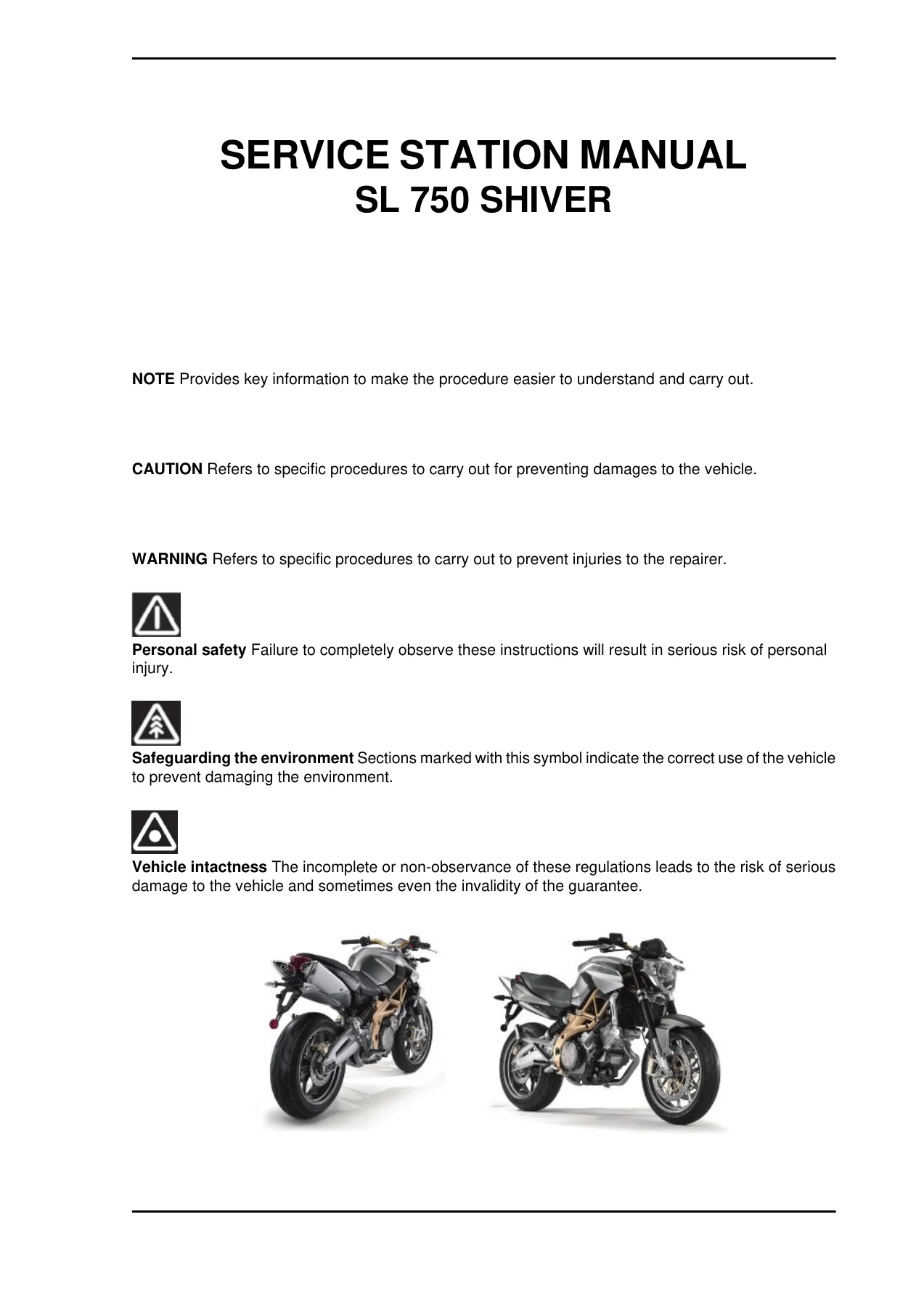
Aprilia SL750 Shiver Service Station Manual 854146 – Complete Workshop & Repair Guide
Original price was: $34.95.$19.95Current price is: $19.95.
The full Aprilia SL750 Shiver Service Station Manual (pub. 854146) — 351 pages of factory workshop procedures for the M551M V-twin, Ride-by-Wire injection, chassis, brakes, suspension, electrical diagnostics and scheduled maintenance.
Description
The Aprilia SL750 Shiver Service Station Manual — publication number 854146 — is the complete workshop reference for the Aprilia SL 750 Shiver motorcycle. Prepared for the Aprilia Official Network, it walks a technician through every major system on the machine: the M551M 90-degree longitudinal V-twin engine with its four-valve heads and dual overhead camshafts, the Ride-by-Wire throttle bodies, the six-speed gearbox, the twin 320 mm front discs, the 43 mm upside-down fork and the adjustable rear monoshock. The same document that Aprilia dealership mechanics work from is reproduced here as an instantly downloadable PDF.
File Details
- Manual type: Service Station Manual (full workshop / repair manual)
- Brand: Aprilia (a Piaggio & C. S.p.A. trademark)
- Model: SL 750 Shiver
- Publication number: 854146
- Copyright: 2007 Aprilia
- Language: English
- Page count: 351 pages
- File format: PDF
Chapters Covered
- Characteristics — dimensions, engine, transmission, capacities, electrical system, frame, brakes, wheels and tyres
- Special Tools — Aprilia service tool catalogue with store codes
- Maintenance — routine maintenance table, spark plugs, engine oil and filter, air filter, valve clearance, running-in
- Troubleshooting — EFI warning light diagnostics and engine-does-not-start flow charts
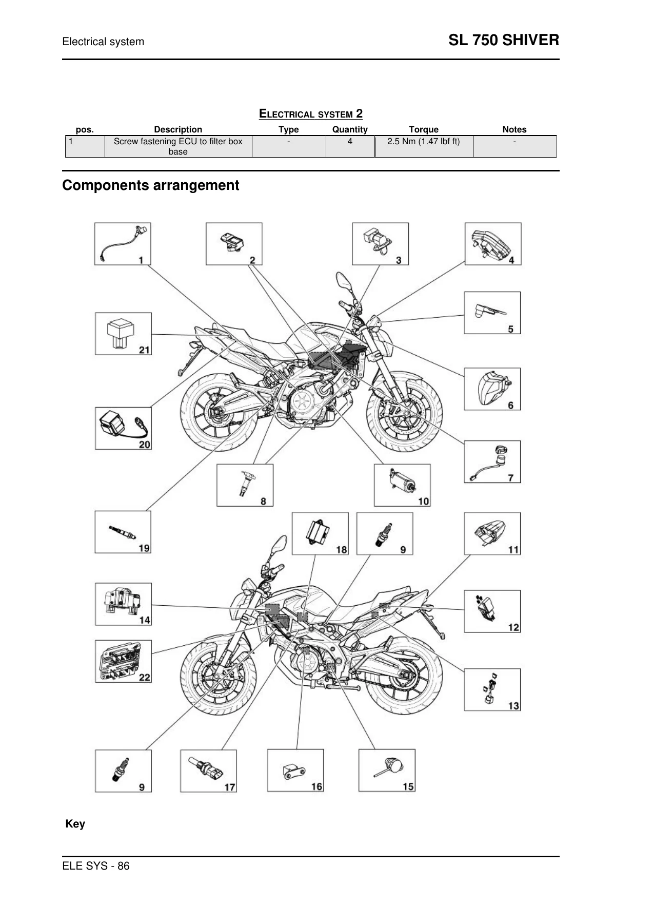
- Electrical System — wiring diagrams, relay layout, cable harness routing, component arrangement
- Engine from Vehicle — removal and installation procedures
- Engine — head cover, cylinder head, overhead camshaft, valves, timing, cylinder-piston assembly, crankcase, crankshaft, gearbox, gear selector, clutch, ignition, starter motor, oil pump
- Power Supply — fuel pump, throttle body, Ride-by-Wire system
- Suspensions — front wheel, handlebar, front fork, steering bearings, rear wheel, shock absorbers
- Chassis — swingarm, drive chain, stand, exhaust
- Braking System — front and rear callipers, brake pads, bleeding procedure, front brake pump
- Clutch System — clutch pump
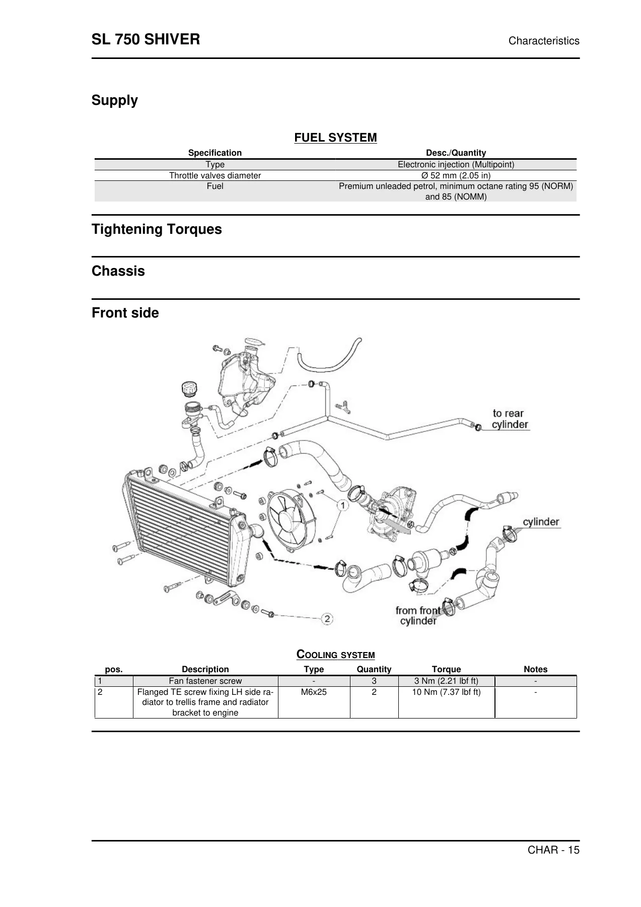
- Cooling System — circuit diagram, electric fan, coolant replacement, water pump, radiator, expansion tank, thermostatic valve
- Bodywork — instrument panel, mudguard, front and rear bodywork, seat, headlamp, taillight, side panels, air box, fuel tank, tail guard
- Pre-Delivery — pre-delivery inspection checklist
Every chapter follows the same workshop discipline: exploded diagrams of each assembly with numbered fasteners, torque values in Nm and lbf ft, tightening sequences, component removal and refitting order, wear limits, and service specifications taken directly from the manufacturer’s data. The Aprilia SL750 Shiver Service Station Manual is not a generalised third-party guide — it is the factory service publication for one specific machine.
What the Manual Covers in Detail
Engine
The manual opens the M551M engine completely. Timing chain removal and cam timing are covered step by step with the Aprilia-specific tools (camshaft gear alignment pin 020718Y, timing pin 020719Y, jig for timing overhead camshafts 020723Y). Cylinder and piston assembly includes the Type A/B/C/D piston-to-cylinder coupling classes, ring side clearances and end gaps, pin and pin-bore measurements, and the base gasket selection procedure using a dial gauge. Crankcase splitting, crankshaft removal, main bushing selection (colour-coded semi-bushings A through E), connecting rod weight classes (E1 to E7) and the desmodromic gear selector are all documented. The lubrication circuit, oil pump rotor-to-stator clearance, oil pressure regulator and oil jet cleaning are included.
Electrical and Diagnostics
The electrical chapter reproduces the full wiring diagrams, relay layout and the location of every major connector on the harness — including the critical connector list the factory flags for correct refitting. The Marelli control unit pin-out is given for both the ENGINE and VEHICLE connectors. Fault codes are described individually (P0105, P0110, P0115, P0130, P0150 through P0156, P0201, P0230, P0336, P0601, P0604, P0605, P0607, U1601, U1602, U1701, U1705, U1706 and many more) with error cause and troubleshooting steps. Throttle self-learning, throttle grip autodetection and the Ride-by-Wire system safety levels are explained so that a tech with an Axone tool can service the injection system correctly.
Chassis, Suspension and Brakes
Front fork disassembly, oil draining and refilling, oil seal replacement, and the difference between the left and right cartridge stems are all spelled out, along with the 43 mm seal fitting tools and the fork spring minimum length limit. Steering bearing preload, front and rear wheel removal sequences, chain tension adjustment (25 mm vertical oscillation) and the swingarm removal procedure are provided. Brake pad replacement, calliper removal, and the air-bleeding procedure for both front and rear circuits are covered in a straightforward workshop order.
Maintenance and Pre-Delivery
The routine maintenance table lists service intervals at 1,000, 5,000, 10,000, 15,000, 20,000, 25,000, 30,000, 35,000 and 40,000 km, showing what to inspect, clean, lubricate, adjust or replace at each stage. Valve clearance (intake 0.11–0.18 mm, exhaust 0.16–0.23 mm), oil capacity (3.0 L without filter change, 3.2 L with), coolant (1.8 L), spark plug gap (0.6–0.7 mm) and the running-in guidance are all included. The pre-delivery section lists the checks the dealership carries out before the bike goes to its first owner.
Tightening Torques and Service Data
Throughout the manual, every reassembly step references a torque value. Front wheel pin nut at 80 Nm, front brake calliper bolts at 50 Nm, rear wheel axle nut at 120 Nm, clutch hub nut at 180 Nm, crankshaft primary gear nut at 270 Nm, connecting rod screws at 15 + 30 Nm + 50 degrees — the manufacturer’s figures are given, in both Nm and lbf ft, for the fasteners that matter for safety and reliability. Each section also carries the wear limits a workshop needs to decide whether a component is serviceable: camshaft lobe dimensions, valve stem clearances, cylinder bore and piston skirt measurements, camshaft eccentricity, fork spring minimum length, brake disc thickness and clutch plate thickness. A manual without these numbers is only half a manual.
Who This Manual Suits
The Aprilia SL750 Shiver Service Station Manual is written for the workshop, and that is exactly the level of detail it delivers. Independent motorcycle mechanics working on Aprilia machines, Aprilia owners with a well-equipped home garage, restoration shops preparing a Shiver for resale, and anyone trying to fix a specific fault without guessing at clearances and torque values — all get a document that was originally supplied to the official Aprilia dealer network for the SL 750 Shiver. It covers one model, in one language, with the manufacturer’s own procedures and specifications.
Why This Manual Matters
Generic online advice about “a V-twin” or “a naked 750” does not tell you where the timing pins go on an M551M, what the correct bushings are for a particular crankcase class, or which of the two connectors on the throttle grip sensor goes left and which goes right. The Aprilia SL750 Shiver Service Station Manual does. Wrong torque on a connecting rod screw or the wrong base gasket thickness on a 749.9 cm³ engine idling at 1400 rpm is not a small mistake — it is engine damage. Having the factory document on hand is what separates a confident repair from a risky one.
IMAGES PREVIEW
Instant PDF Delivery
The complete 351-page Aprilia SL750 Shiver Service Station Manual is delivered as a single PDF file. There is no physical shipment and no waiting — the download link is available immediately after payment. The file opens on any computer, tablet or smartphone with a PDF reader, can be printed page by page if a greasy paper copy is easier to use next to the bike, and can be stored on the workshop laptop for future reference. Buy the manual once and you have the SL 750 Shiver factory service information for as long as you own the bike.

Reviews
There are no reviews yet.