
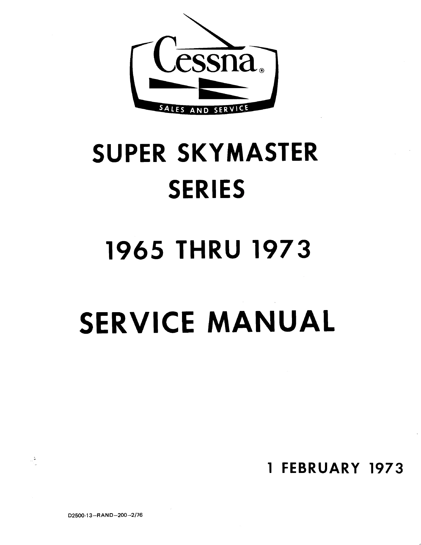
1965-1973 Cessna 337 & T337 Series Super Skymaster Service Manual
Original price was: $44.95.$26.95Current price is: $26.95.
Factory service manual D2500-13 for 1965-1973 Cessna 337, T337, and Reims F337/FT337 Super Skymaster twin-engine aircraft. Comprehensive 826-page workshop manual covering airframe systems, Continental IO-360 and TSIO-360 engines, hydraulic landing gear retraction, flight control rigging, electrical systems, and full wiring diagrams.
Description
Technical File Details
- Manual Type: Aircraft Service Manual
- Brand: Cessna Aircraft Company
- Model Coverage: Cessna 337, 337A, 337B, 337C, 337D, 337E, 337F, 337G, T337B, T337C, T337D, T337E, T337F, Reims/Cessna F337E, F337F, F337G, FT337E, and FT337F
- Document Number: D2500-13 (D2500-13-RAND-200-2/76)
- Revision / Issue Date: 1 February 1973 (incorporating Service Manual Change Notices thru March 12, 1976)
- Language: English
- Page Count: 826 pages
- File Format: Portable Document Format (PDF)
Comprehensive Airframe & Systems Service Overview
The 1965-1973 Cessna 337 & T337 Series Super Skymaster Service Manual provides comprehensive maintenance, inspection, rigging, and overhaul procedures for Cessna’s distinctive centerline-thrust twin-engine aircraft. Operating two engines configured in tandem along the fuselage centerline eliminates asymmetric thrust during single-engine operations, but introduces unique mechanical, structural, and cooling engineering across the airframe. This service manual supplies aircraft maintenance technicians, certified A&P mechanics, and aircraft owners with factory-authorized technical data necessary to service, troubleshoot, and maintain these high-performance push-pull twins safely and accurately.
Spanning model years 1965 through 1973, this workshop publication incorporates all interim Service Manual Change Notices issued through March 1976, ensuring updated gross weight figures, adjusted inspection schedules, and clarified fuel pump pressure regulation procedures. From routine 50-hour and 100-hour periodic inspections to complex landing gear actuator teardown, control cable tensioning, and 24-volt electrical fault isolation, every procedure in this Cessna 337 service manual is presented with explicit technical instructions, torque tables, clearance tolerances, and engineering schematics.
IMAGES PREVIEW
Manual Chapters & Systems Coverage
- Section 1 — General: Airframe leading particulars, aircraft dimensions, fuselage, wing, and tail boom station reference diagrams, and standard/alternate nut torque tables for coarse and fine thread series.
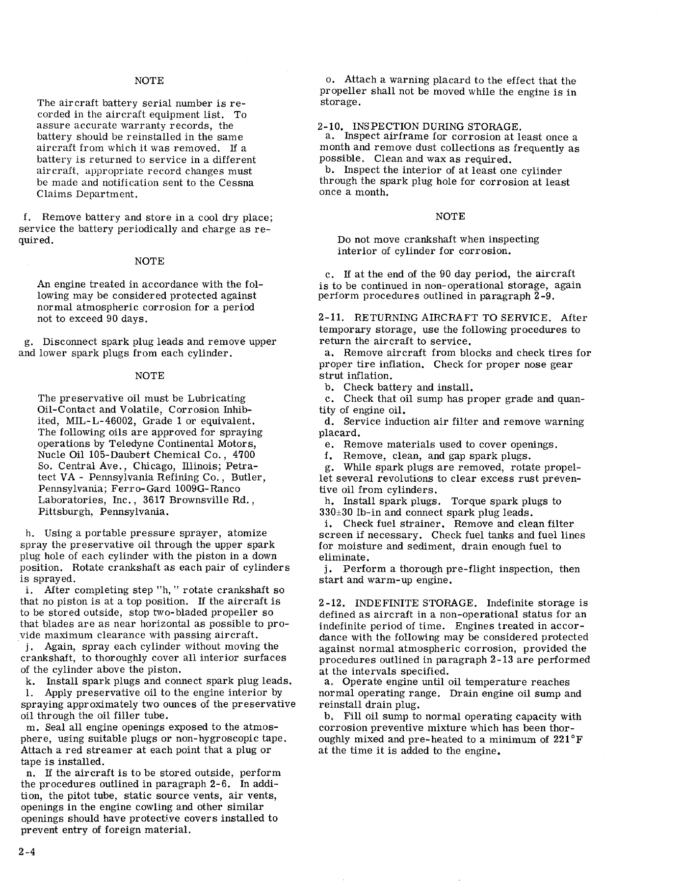
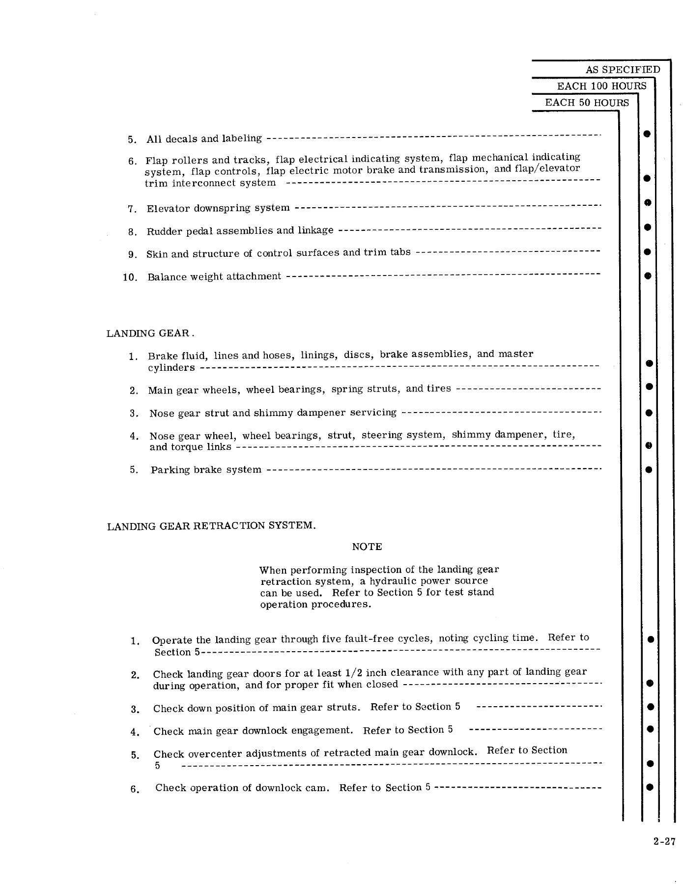
- Section 2 — Ground Handling, Servicing, Lubrication, and Inspection: Towing limitations (39-degree steering limit), three-ton hoisting instructions, multi-point jacking procedures, tail weighting methods, tie-down techniques, flyable and indefinite storage preservation, system servicing intervals, airframe cleaning, lubrication point charts, and structured 50-hour, 100-hour, and annual inspection checklists.
- Section 3 — Fuselage: Windshield and window replacement, optical scratch polishing, crack stop-drilling, single-piece and two-piece clamshell cabin entrance door rigging, rotary clutch door latch indexing, baggage door installation, front articulating recline seats, power seat jack screws, center fold-up seating, soundproofing installation, and detachable belly cargo pack mounting.
- Section 4 — Wings, Booms, and Empennage: Semi-monocoque wing panel removal and installation, wing lift strut fairings and internal cable routing, elliptical tail boom structural attachments, horizontal stabilizer alignment, twin vertical fins, and retractable mooring rings.
- Section 5 — Landing Gear, Brakes, and Hydraulic System: Main landing gear spring-steel struts and articulated gear assemblies, universal joints, pivot shafts, hydraulic actuator cylinder disassembly, mechanical uplocks and downlocks, wheel and strut doors sequencing, nose gear air-oil shock strut servicing, shimmy dampener fluid bleeding, wheel alignment (camber and toe-in), master brake cylinder overhaul, hydraulic power pack operations, emergency hand pump checks, and system pressure troubleshooting.
- Section 6 — Aileron Control System: Control wheel quadrants, carry-thru cable routing, aileron bellcranks, rod end bearings, and cable tension adjustments.
- Section 7 — Wing Flap Control System: Electric motor and transmission, mechanical drive shafts, screw jack actuators, inboard and outboard flap synchronization, and limit switch rigging.
- Section 8 — Elevator, Elevator Trim, and Flap/Elevator Trim Interconnect Systems: Dual control column mechanisms, push-pull tubes, elevator bellcranks, trim tab actuators, mechanical downsprings, and flap-interconnect cable compensation.
- Section 9 — Rudder and Rudder Trim Control System: Dual rudder pedal assemblies, boom cable fairleads, twin fin bellcranks, rudder stops, and cockpit trim wheel rigging.
- Section 10 — Engines (Non-Turbocharged): Continental IO-360 series powerplant removal and installation, dynamic dynafocal mounts, cowl flap rigging, induction airboxes and filters, fuel injection pump calibration, ignition harness and magneto internal timing, lubrication system, and exhaust collector systems.
- Section 10A — Engines (Turbocharged): Continental TSIO-360 series turbocharged installations, exhaust-driven turbochargers, wastegate actuator adjustments, absolute and variable pressure controllers, pressurized fuel pump vapor lines, and cold-weather induction precautions.
- Section 11 — Fuel System: Standard and auxiliary wing fuel cells, fuel strainer cleaning and relocated drain controls, engine-driven and electric auxiliary boost pumps, vapor return lines, and fuel quantity transmitter calibration.
- Section 12 — Propellers and Propeller Governors: McCauley two-blade constant-speed, full-feathering front and rear propellers, governor oil pressure routing, unfeathering accumulator charging, and propeller synchronizer linkages.
- Section 13 — Utility Systems: Exhaust heat exchangers, internal combustion auxiliary cabin heater inspection and overhaul periods, oxygen cylinder charging, regulator distribution, and pneumatic surface de-ice boot plumbing.
- Section 14 — Instruments and Instrument Systems: Pitot-static plumbing, manifold pressure and fuel flow indicators, central vacuum relief valves, engine-driven vacuum pumps, and gyro instrument filters.
- Section 15 — Electrical Systems (Thru 1970 Models): 24-volt direct current single-wire systems, engine-driven alternators, mechanical and transistor voltage regulators, battery maintenance, external ground power receptacles, and circuit breaker distribution.
- Section 15A — Electrical Systems (1971 and On): Redesigned split-bus electrical architecture, paralleling alternator controls, centralized circuit breaker panels, and solid-state regulator protection.
- Section 16 — Structural Repair: Sheet metal skin patching, spar web and cap splice repairs, stringer reinforcement, riveting specifications, and fiberglass molding repair methods.
- Section 17 — Exterior Painting: Surface preparation, chemical conversion coatings, corrosion-inhibiting wash primers, and finish coating techniques.
- Section 18 — Wiring Diagrams: 182 pages of dedicated electrical wiring schematics detailing wire coding, harness routing, circuit breakers, and component terminations across every model year and production block.
By compiling every primary system into a single cohesive publication, this workshop manual gives the aviation professional clear diagnostic paths, exact assembly clearances, and complete visual schematics needed to return any Model 337 aircraft to airworthy factory tolerances.
Extensive Model Year & Serial Range Coverage
This manual covers the complete production range of naturally aspirated and turbocharged 337 models manufactured between 1965 and 1973 by Cessna Aircraft Company in Wichita, Kansas, as well as licensed variants built by Reims Aviation in France. The cross-reference tables establish precise model and serial coverage:
- Cessna 337 Super Skymaster: Model 337 (1965, Serials 337-0001 thru 337-0239); Model 337A (1966, Serials 337-0240 thru 337-0525); Model 337B (1967, Serials 337-0526 thru 337-0755); Model 337C (1968, Serials 337-0756 thru 337-0978); Model 337D (1969, Serials 337-0979 thru 33701193); Model 337E (1970, Serials 33701194 thru 33701316); Model 337F (1971, Serials 33701317 thru 33701398; 1972 Skymaster, Serials 33701399 thru 33701462); Model 337G (1973 Skymaster, Serials 33701463 and on).
- Turbo-System Super Skymaster: Model T337B (1967, Serials 337-0526 thru 337-0755); Model T337C (1968, Serials 337-0756 thru 337-0978); Model T337D (1969, Serials 337-0979 thru 33701193); Model T337E (1970, Serials 33701194 thru 33701316); Model T337F (1971, Serials 33701317 thru 33701398).
- Reims/Cessna Super Skymaster: Model F337E (1970, Serials F33700001 thru F33700024); Model F337F (1971, Serials F33700025 thru F33700045; 1972 Skymaster, Serials F33700046 thru F33700055); Model F337G (1973 Skymaster, Serials F33700056 and on).
- Reims/Cessna Turbo-System Super Skymaster: Model FT337E (1970, Serials F33700001 thru F33700024); Model FT337F (1971, Serials F33700025 thru F33700045).
Complex Hydraulic & Landing Gear Retraction Systems
Servicing the landing gear on the Cessna Skymaster requires meticulous attention to hydraulic actuation and sequencing. Thru 1971 models, the aircraft incorporates a hydraulically actuated gear retraction system operating in conjunction with landing gear doors, mechanical uplock hooks, downlock pins, and overcenter buttons. Beginning with 1972 models (Model 337G and late 337F aircraft), Cessna engineered tubular steel spring gear assemblies.
The manual provides complete hydraulic schematics and step-by-step disassembly guides for the main gear actuators, strut door cylinders, and hydraulic power pack. Critical tolerances are emphasized throughout the text: main landing gear doors must maintain at least 1/2-inch clearance from any portion of the landing gear during operation. In addition, technicians are provided with full procedures for checking hydraulic pump isolation on dual-pump installations, servicing the nose gear air-oil shock strut with MIL-H-5606 fluid to 35 psi (extended) or 42 psi tire pressures, adjusting the nose shimmy dampener, and performing gear-swing tests using external hydraulic power units.
Continental Powerplant Support & Flight Control Rigging
Extensive coverage is dedicated to maintaining the fuel-injected six-cylinder horizontally opposed Continental engines powering the series: the naturally aspirated Continental IO-360 Series and the turbocharged Continental TSIO-360 Series. Technicians will find complete instructions for fuel injection pump adjustment, idle speed and mixture balancing, cowl flap push-pull rod rigging (maintaining a 1.75-inch opening at the cowl trailing edge on non-turbo models), magneto internal timing, and oil screen and filter element maintenance.
Flight control surfaces require exacting cable tension settings across the high-wing and twin-boom geometry. The manual specifies travel angles and millimeter/inch tolerances for all primary controls:
- Aileron Travel: 21° ± 2° Up; 14° 30′ ± 2° Down.
- Wing Flap Travel: Inboard and outboard flaps travel 0° to 25° (+1°, -2°).
- Rudder Travel: Measured perpendicular to hinge centerline: 25° ± 2° Outboard; 17° (+0°, -2°) Inboard.
- Elevator Travel: Thru Model 337C: 21° ± 30′ Up, 15° ± 2° Down. Beginning with 337D and On: 26° ± 1° Up, 15° ± 1° Down.
- Elevator Trim Tab Travel: Up to 20° ± 1° Up and 15° ± 1° Down depending on serial series, including specific flap/elevator trim interconnect travel limits.
Professional Maintenance Capability & Instant Digital Delivery
Armed with this 1965-1973 Cessna 337 & T337 Series Super Skymaster Service Manual, certified repair stations, aircraft mechanics, and skilled owner-operators can tackle everything from minor line maintenance to complete airframe rebuilds. Perform reliable annual inspections, troubleshoot intermittent landing gear indicator switches, adjust fuel injection pump pressures using the slothead needle valve, rig twin vertical fin rudders, and trace complex cockpit circuits through 182 pages of high-resolution electrical schematics.
Following genuine Cessna service methods protects aircraft value, prevents structural and mechanical damage caused by trial-and-error adjustments, and guarantees strict compliance with factory airworthiness standards. This publication is delivered as an instant digital PDF download immediately upon checkout. With no physical shipping wait, you can download the entire 826-page workshop manual instantly to your laptop, tablet, or workshop computer, zoom into fine schematics on screen, or print exact chapters and diagrams for hands-on reference right at the hangar bench.
Reviews
There are no reviews yet.