
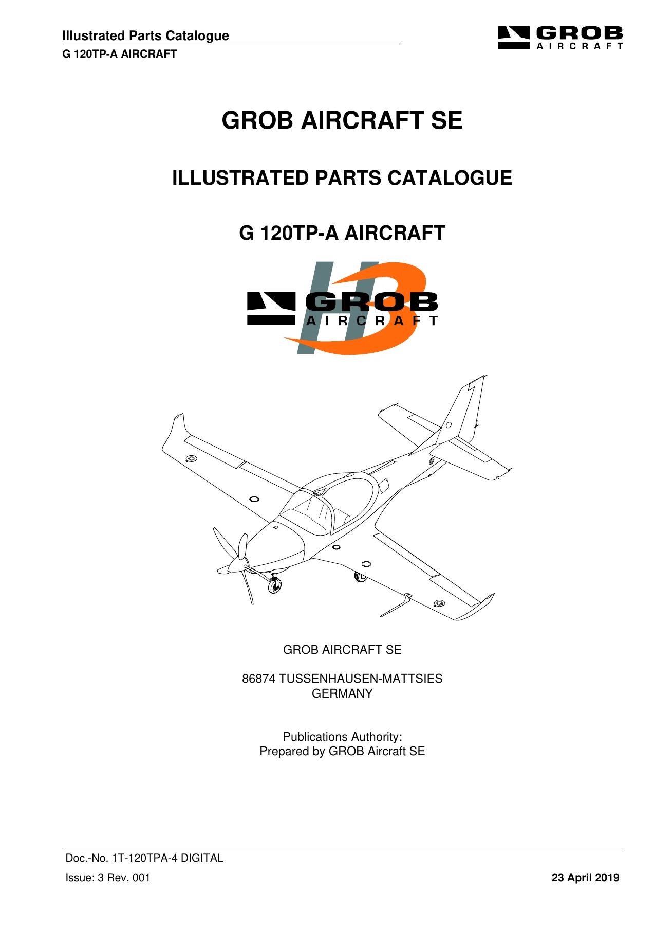

Grob G 120TP-A Aircraft Illustrated Parts Catalogue (Doc No. 1T-120TPA-4 DIGITAL, Issue 3 Rev 001)
Original price was: $49.95.$29.95Current price is: $29.95.
Official Grob Aircraft SE Illustrated Parts Catalogue for the Grob G 120TP-A turboprop training aircraft. Features full system breakdowns, exploded assembly diagrams, standardized NATO CAGE codes, and complete part numbering from ATA Chapter 00 through Chapter 80.
Description
Grob G 120TP-A Aircraft Illustrated Parts Catalogue (Doc No. 1T-120TPA-4 DIGITAL, Issue 3 Rev 001) Overview
The Grob G 120TP-A Aircraft Illustrated Parts Catalogue (Doc No. 1T-120TPA-4 DIGITAL, Issue 3 Rev 001) represents the definitive factory parts reference published by GROB Aircraft SE in Tussenhausen-Mattsies, Germany. Formatted under the rigorous international aerospace standards of ASD S1000D Issue 4.1 and structured using the standard Air Transport Association Specification 100 (ATA 100) numbering layout, this technical catalog provides comprehensive procurement, identification, and breakdown data for the high-performance Grob G 120TP-A military and aerobatic trainer certified under EASA.A.565. From the Rolls-Royce 250-B17F turboprop engine accessories to the five-blade MT-Propeller system and Genesys Aerosystems IDU 680 digital avionics, every line-replaceable unit and structural assembly is thoroughly illustrated with detailed exploded schematics and precision part numbering.
File Details
- Manual Type: Illustrated Parts Catalogue (IPC)
- Brand: GROB Aircraft SE
- Model: Grob G 120TP-A Aircraft
- Applicable Engine: Rolls-Royce 250-B17F Turboprop
- Document Number: 1T-120TPA-4 DIGITAL
- Issue / Revision: Issue 3, Revision 001
- Publication Date: 23 April 2019
- Compliance Standards: ASD S1000D Standard Issue 4.1 / ATA 100
- Language: English
- Format: Digital PDF
Chapters Covered
- Chapter 00 — General & Introduction: Record of Revisions, Temporary Revisions, Service Bulletins, Service Letters, S1000D/ATA 100 Introduction, Drawing & Part Numbering Nomenclature, and Master Numerical Index
- Chapter 01-00 — Aircraft Maintenance Manual Reference Data: Publication queries, Air Publication Query Report template, and ATA 100 breakdown logic
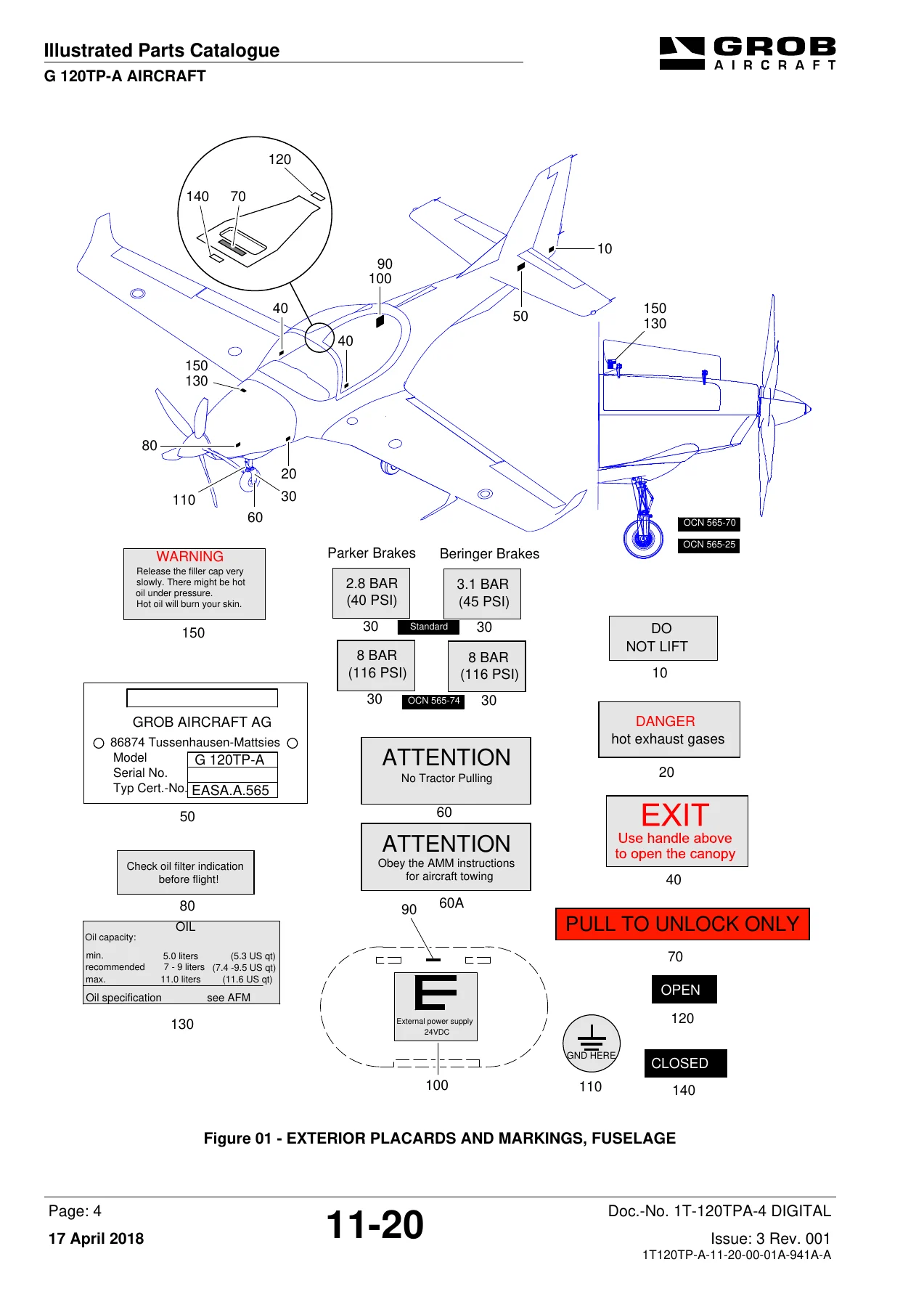
- Chapter 11 — Placards and Markings: Exterior Fuselage Markings, Exterior Wing Placards, Fuel Cap Markings, Interior Cockpit Placards, Instrument Panel Markings, and Aerobatic/Spin Limitations
- Chapter 21 — Air Conditioning & Pressurization: Cockpit Air Distribution, Ventilation Ducting, Cabin Heating Assembly, Cooling Compressor Installation, Refrigerant Lines, Evaporator Assembly, and Bleed Air Shut-Off Valves
- Chapter 23 — Communications: Digital Communications Architecture, UHF Transceiver KTR 909 Installation, VHF Transceiver ADR-7050, Audio Management Unit AMU50-001, Loudspeaker Panels, and Static Dischargers
- Chapter 24 — Electrical Power: 24V DC Generation, Battery Box Installation (Hawker 25Ah and Concorde RG390ES 28Ah), DC Current Sensors, External Power Receptacle, Main Crossbar Assembly, RH & LH Circuit-Breaker Panels, Relay Trays, and 5VE Bracket
- Chapter 25 — Equipment and Furnishings: Cockpit Layout, Crew Seats with 5-Point Aerobatic Harness Assemblies, Instrument Panel Coaming, Center Console Pedestal Covers, Artex C406-4 Emergency Locator Transmitter (ELT), Flyaway Kit, and Emergency Gear
- Chapter 26 — Fire Protection: Cockpit Portable Fire Extinguisher Installations (Baseline and Alternative Configurations)
- Chapter 27 — Flight Controls: Primary Controls Architecture, Dual Control Column Assemblies, Push-Pull Rods, Aileron Bellcranks, Fuselage & Wing Aileron Controls, Aileron/Rudder Trim Panels, Rudder Pedal Assemblies, Rudder Cable Runs, Center Unit Levers, Elevator Linkages, Center Console Trim Wheels, and Flap Actuation Mechanisms
- Chapter 28 — Fuel System: Sensoring Unit, Submerged Boost Pumps 1 & 2, Fuel Filter Assemblies, Pump Interconnect Piping, Wing Fuel Cells, Sump Drains, and Ground/In-Flight Refueling Lines
- Chapter 30 — Ice and Rain Protection: Pitot Heat, Stall Warning Vane De-Ice Integration, and Windshield Defogging Ducts
- Chapter 31 — Indicating & Recording Systems: Central Display Panels, Digital Instrument Layout, Dual IDU 680 Central Displays, Data Acquisition Unit (DAU), Analog Interface Unit (AIU), Aural Message Generator, and Flight Data Recorder V2 (Option 22)
- Chapter 32 — Landing Gear: Main Landing Gear Pre-Assembly and Legs, Nose Landing Gear Assembly with Drag Braces, Hydraulic Retraction/Extension Actuators, Up-Locks, Down-Locks, Nose Wheel Steering Mechanisms, Parker Wheel & Brake Assemblies, and Beringer High-Performance Brake Conversion (Option 57)
- Chapter 33 — Lighting: Cockpit Floodlighting, Instrument Panel Luminescence, Canopy Dome Lighting, Exterior Navigation/Position Lights, Anti-Collision Strobes, and Optional Taxi/Landing Gear-Down Lights
- Chapter 34 — Navigation: Pitot-Static Probes with Integrated OAT, ADAHRS Modules, Magnetometers, Traffic Advisory System (TAS605), Becker ADF 3500, Distance Measuring Equipment (Honeywell KN 63 DME), Mode-S Transponder, and GPS/SBAS Antennas & Receivers
- Chapter 35 — Oxygen System: Crew Oxygen Storage Cylinder, Mounting Racks, High-Pressure Supply Lines, Overpressure Discharge, Regulators, and Cockpit Distribution Ports
- Chapter 52 — Doors & Canopy: Jettisonable Canopy Structure, Sliding Track Mechanism, Locking Latches, Internal/External Emergency Release Handles, and Wing & Fuselage Quick-Release Access Panels
- Chapter 53 — Fuselage: Composite Monocoque Fuselage Structure, Cockpit Floor Pans, Adjustable Seat Tracks, Rudder Travel Stops, and Empennage Structural Attachment Hardware
- Chapter 55 — Stabilizers: Horizontal Stabilizer Structure, Vertical Fin, Left-Hand & Right-Hand Elevator Assemblies with Trim Tabs, and Rudder Surface Installation
- Chapter 56 — Windows: Optical Acrylic Canopy Transparency, Side Sliding Vents, and Windshield Bonding Interfaces
- Chapter 57 — Wings: Carbon-Fiber Main Wing Unit, Centerline & Fuselage Attachment Hardware, Fowler Flap Hinges & Roller Bearings, Aileron Actuating Horns, and Counterbalance Ballast Weights
- Chapter 61 — Propeller: MT-Propeller MTV-5-1-D-C-F-R(A)/CFR210-56 Five-Blade Constant-Speed Propeller Hub, Composite Blades, Spinner Assembly, and Governor Integration
- Chapter 71 — Power Plant: Upper & Lower Composite Engine Cowlings, Tubular Steel Engine Mount Truss, Lord Elastomeric Shock Mounts, Engine Compartment Wiring Harnesses, Air Intake Scoop, and Drain Manifolds
- Chapter 72 — Engine: Rolls-Royce 250-B17F Turboprop Powerplant Integration, Core Mounting Pads, and Secondary Structural Attachments
- Chapter 74 — Engine Ignition: Dual Capacitive Discharge Ignition Exciters, High-Tension Leads, and Igniter Plugs
- Chapter 76 — Engine Controls: Cockpit Power Lever Quadrant, Power Coordinator Unit, Electronic Engine Control (EEC/ECU) Mounting, and Mechanical Throttle/Condition Linkage Rods
- Chapter 77 — Engine Indicating: Tachometer-Generator Sensor, Oil Pressure & Temperature Transducers, Fuel-Flow/Temperature Transmitter, Air/Fuel Separator, and Torquemeter Transducer
- Chapter 78 — Exhaust: Twin Stainless-Steel Turbine Exhaust Ejector Nozzles, Fairings, and Clamps
- Chapter 79 — Engine Oil System: Main Oil Reservoir, Oil Cooler Lines, Acrobatic Inverted Flight Oil System, and Acrobatic Inverted Shuttle Valve Assembly
- Chapter 80 — Engine Starting: Starter-Generator Installation, Drive Splines, Generator Control Unit (GCU), and Heavy-Duty Starting Contactors
Together, these chapters equip aircraft engineers, maintenance organizations, and parts specialists with an exhaustive, fully cross-referenced breakdown of every single component that forms the Grob G 120TP-A airframe, propulsion group, and avionics suites.
Grob Drawing Identification and Standard Parts Architecture
A vital operational benefit of this catalog is its complete transparency regarding part nomenclature and manufacturing hierarchies. Grob Aircraft SE utilizes an explicit component drawing numbering code defined in Chapter 01-00 as AA-B-CCDE-FFFF-GG/HH-I. Technicians can immediately decipher any component: AA identifies the aircraft line (2T for Grob G 120TP), B denotes the airframe model (A for G 120TP-A), CC indicates the functional GRATA chapter matching standard ATA designations, D specifies the sub-system, and E designates assembly hierarchy and zone (with odd numbers 1, 3, 5, 7, 9 assigned to left-hand components and even numbers 2, 4, 6, 8 for right-hand installations). The assembly tier FFFF establishes whether a part is a primary assembly (1000) or subcomponent (1111), while GG, HH, and I establish sequential numbering, modification options (such as Option 57 for Beringer brakes or Option 74 for gross mass increases), and non-interchangeable structural variants.
Furthermore, standard hardware across all illustrated assemblies is comprehensively cataloged with international aerospace identifiers. Technicians will find exact DIN, LN, MS (Military Standard), and NAS (National Aerospace Standard) part numbers alongside NATO Commercial and Government Entity (NCAGE) vendor codes (such as C4331 for Grob Aircraft SE, 96906 for military standards, and D8286 for DIN). The catalog also integrates an explicit two-character Interchangeability (ICY) matrix (codes 0 through 9), giving maintenance personnel unambiguous confirmation of forward, backward, or one-way supersession rules before ordering replacement hardware.
Factory-Accurate Sourcing for Scheduled Maintenance and Overhaul
Whether performing a routine 100-hour inspection, resolving an electrical bus fault, overhauling the retractable landing gear actuators, or replacing hydraulic hoses on the aerobatic inverted oil system, using the authentic Grob G 120TP-A Aircraft Illustrated Parts Catalogue (Doc No. 1T-120TPA-4 DIGITAL, Issue 3 Rev 001) ensures total sourcing accuracy. It eliminates the risks of ordering incompatible fasteners, incorrect seal compounds, or obsolete avionics bracketry. Every illustrated page pairs directly with an adjacent tabular parts list detailing item callouts, official nomenclature, quantities per assembly, vendor codes, and exact supersession histories.
Immediate Digital Delivery and Technical Capability
Investing in the Grob G 120TP-A Aircraft Illustrated Parts Catalogue provides airframe technicians, defense operators, civil flight academies, and aircraft restorers with immediate operational autonomy. By relying exclusively on factory-authorized engineering drawings, exploded assembly diagrams, and verified Grob Aircraft SE part numbers, maintenance teams can maintain continued airworthiness, optimize spare parts inventory, and execute component replacements in exact compliance with EASA and military certification baselines. Delivered as an instant high-resolution digital PDF, this manual requires no shipping downtime and is immediately accessible across desktop workstations, hangar laptops, and ruggedized flight-line tablets, with full high-resolution printing capability for maintenance task cards and parts requisitions.
Reviews
There are no reviews yet.