
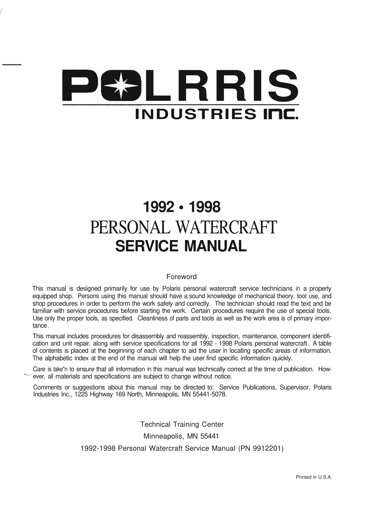
1992-1998 Polaris Personal Watercraft Service Manual PN 9912201
Original price was: $39.95.$24.95Current price is: $24.95.
Comprehensive workshop service manual covering 1992 to 1998 Polaris personal watercraft, including SL650, SL750, SLT, SLX, SL700, Hurricane, SL780, SL900, SL1050, SLTX, SLH, SLTH, and SLXH models. Features full factory repair procedures, engine overhaul, Mikuni and Keihin carburetor calibration, jet pump rebuilding, electrical wiring, and periodic maintenance specifications.
Description
File Details
- Manual Type: Factory Service Manual
- Brand: Polaris Industries Inc.
- Model Coverage: All 1992-1998 Polaris Personal Watercraft (SL, SLT, SLX, SLH, SLTH, SLXH, SLTX, Hurricane Series)
- Publication Part Number: 9912201 (Includes 5/98 Addendum)
- Language: English
- Page Count: 577
- File Format: Portable Document Format (PDF)
Comprehensive Workshop Coverage for Polaris Watercraft
The 1992-1998 Polaris Personal Watercraft Service Manual PN 9912201 provides dedicated, professional-grade technical guidance for servicing, maintaining, and overhauling Polaris personal watercraft produced throughout the 1992 through 1998 model years. Developed directly by the Polaris Technical Training Center for dealership technicians and marine service facilities, this comprehensive manual supplies complete mechanical theory, diagnostic routines, step-by-step disassembly and assembly instructions, and exact factory tolerances. Whether executing a seasonal tune-up, tracing an erratic electrical condition, or conducting a complete engine rebuild, this Polaris personal watercraft service manual provides the exact technical procedures required to perform the job correctly.
Chapters Covered
- Chapter 1 — General Information
- Publication Part Numbers and Reference Charts
- Service Bulletin Index by Bulletin Number and Model
- Factory Paint Codes, Gel Coat Repair Kits, and Structural SMC Adhesives
- Hull Identification Numbers (HIN) and Engine Identification Number Locations
- Comprehensive Model Specifications (1992-1993, 1994-1995, 1996-1997, 1998)
- Standard SAE and Metric Stainless Steel Fastener Torque Specifications
- Decimal Equivalents and Metric Conversion Tables
- SAE and Metric Tap Drill Sizing Charts
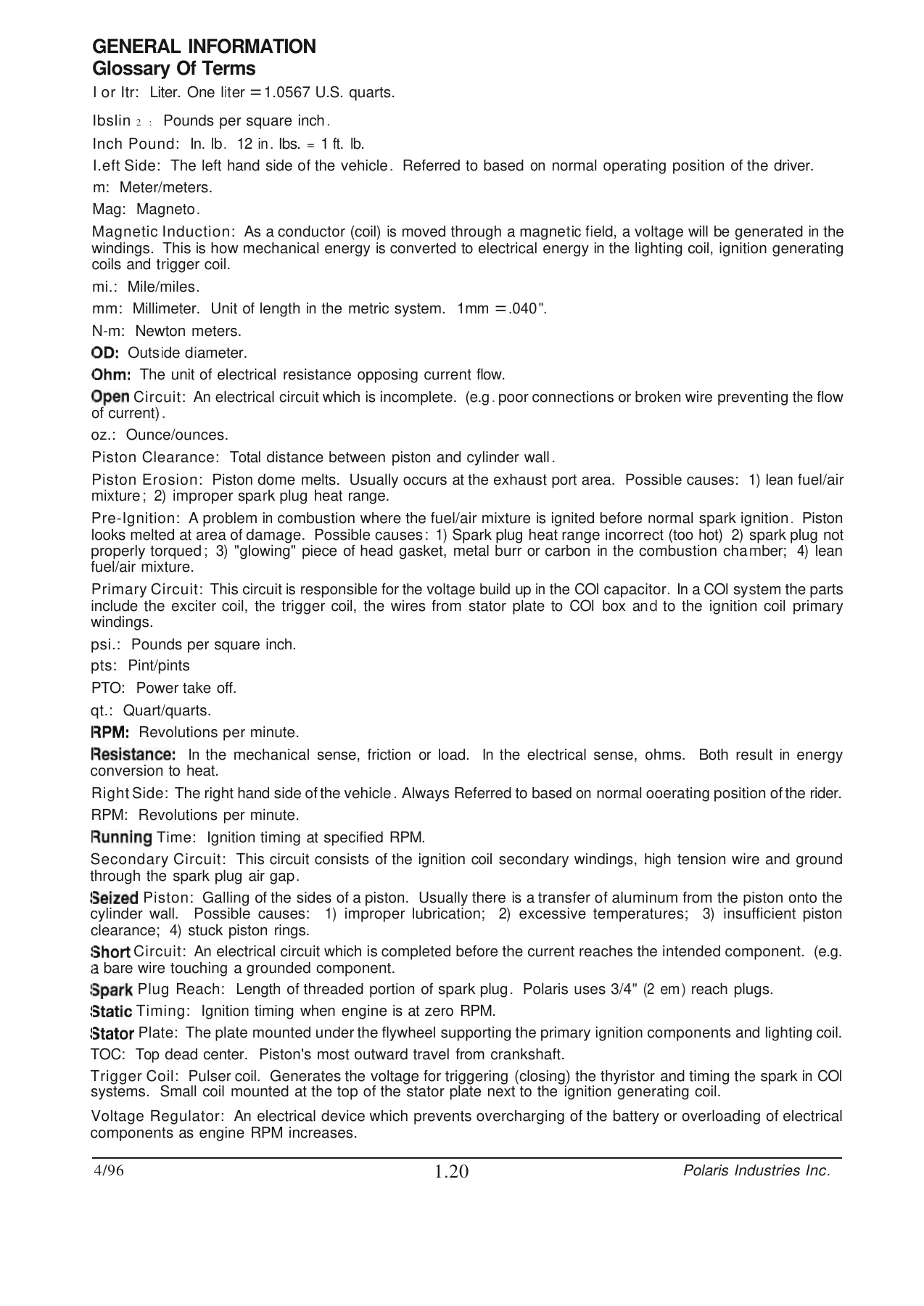
- Glossary of Technical Marine and Engine Terms
- Special Service Tools (Engine, Electrical, Jet Pump, and Fuel System)
- Technician Service Tips and Polaris Limited Warranty Policies
- Chapter 2 — Maintenance / Tune Up
- Periodic Maintenance Intervals and Saltwater Operation Schedules
- Recommended Marine Lubricants, Sealants, and Chemical Protectants
- Choke, Throttle, and Steering Cable Lubrication
- Driveshaft Coupler and Bearing Housing Greasing (Solid and Bonded Rubber Couplers)
- Electrical System Maintenance, Terminal Boards, and Handlebar Switch Torquing
- Battery Safety, Electrolyte Testing, Charging Rates, and 15A Circuit Breaker Service
- Engine Compression Testing and Resistor Spark Plug Specifications
- Ignition Timing Conversion (Degrees BTDC to Piston Position in Inches and Millimeters)
- Cylinder Head, Cylinder Base, and Exhaust Manifold Fastener Re-Torque Sequences
- Exhaust Cooling Orifice and Inline Screen Cleaning
- Thermostat and Internal Pop-Off Valve Inspection and Cleaning
- In-Water Idle Speed Adjustment and Throttle Cable Free Play Calibration
- Oil Filter Replacement and Oil Injection Pump Linkage Adjustments (Fuji and Domestic Engines)
- Steering Cable Centering, Nozzle Pivot Alignment, and Reverse Linkage Setup
- Air Intake Silencer Maintenance (Standard Elements and Vortex Air Cleaners)
- Fuel and Vent Line Routing, Fuel Shut-Off Valve, and Fuel/Water Separator Care
- Mikuni and Keihin Carburetor Synchronization (Manometer and Manual Wire Gauge)
- Cooling System Fresh Water Flushing and Daily Saltwater Corrosion Prevention
- End-of-Season Storage, Engine Draining, RV Antifreeze Protection, and Cylinder Fogging
- Bilge Siphon Pickup Systems, Hull Drain Plugs, and Electric Bilge Pumps
- Mechanical and Electric Quick Trim System Calibration
- Submerged Engine (Hydrolock) Immediate Dewatering Procedures
- Jet Pump Intake Grate, Sacrificial Anode, and Impeller-to-Wear-Ring Clearance Checks
- Seat Seal Adjustment, Storage Compartment Door Alignment, and Hurricane Sponson Blocks
- Comprehensive Diagnostic Troubleshooting Trees (Lean/Rich Running, Detonation, Overheating, Hydrolock)
- Chapter 3 — Fuel System / Carburetion
- Detailed Carburetor Jetting Specifications and Factory Calibration Baseline Settings
- Genuine Mikuni and Keihin Jet Part Number Identification Charts
- High-Elevation Jetting and Impeller Pitch Recommendations (Above 5,000 Feet)
- Vent Line and Fuel Delivery Hose Routing Diagrams by Model and Year
- Fuel Tank Assembly, In-Tank Pickup Screens, Sender Units, and Drop Tube Retainers
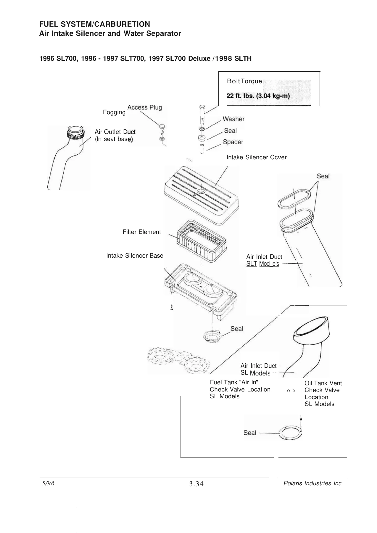
- Air Silencer Ducting, Water Separator Drain Lines, and Flame Arrestor Housings
- Exploded Views and Part Callouts for Mikuni Super BN and Keihin CDK II Assemblies
- Remote Oil Tank Removal, Sensor Inspection, and Inline Oil Check Valves
- Engine-Driven Variable Oil Pump Assemblies, Drive Gears, and Bleeding
- Carburetor Fuel Hose Connections and Impulse Line Plumbing (Twin and Triple Engines)
- Fuel Metering Theory and Operational Stages (Low-Speed, Mid-Range, High-Speed, Choke)
- Inlet Needle and Seat Pop-Off Pressure Benchmarks and MityVac Pressure Testing
- Crankcase Impulse Diaphragm Fuel Pump Rebuilding, Valve Inspection, and Testing
- Fuel Cock Shut-Off Valve Teardown, Internal Seals, and Fuel Filter Maintenance
- Fuel/Water Separator Servicing, Internal Float Operation, and Filter Elements
- Carburetor Removal, Complete Ultrasonic Cleaning, Jet Inspection, and Needle Replacement
- Accelerator Pump Mechanism Overhaul, Check Valves, and Diaphragms
- Fuel Tank Pressure Relief Valves (1.5 PSI), Roll-Over Valves, and Tank Vent Testing
- Intake Manifold Removal, Reed Block Inspection, Petal Lift Limits, and Gasket Sealing
Together, these technical chapters provide an exhaustive resource for marine technicians and owners. From foundational engineering data and fluid capacities to detailed exploded component diagrams, the manual removes all guesswork from personal watercraft maintenance, allowing technicians to diagnose complex running issues and rebuild major sub-assemblies with complete confidence.
Engine Mechanics & Factory Specifications
The 1992-1998 Polaris Personal Watercraft Service Manual PN 9912201 provides full coverage for both the Fuji-manufactured 3-cylinder engines and the American-built Polaris domestic 2-stroke twin and triple engines. Covered displacement categories include the 647cc (EC65PW), 744cc (EC75PW), and 779cc (EC78PW) Fuji powerplants, alongside the 700cc twin (WC70DCSP), 889cc/900cc triple (WC90TCSP), and 1050cc triple (WC105TCSP) domestic power units. The manual documents exact cylinder bore and stroke dimensions, full-stroke compression ratios ranging from 6.4:1 up to 12.0:1, horsepower ratings spanning 68 HP to 120 HP, and standard operating cylinder compression specifications of 120 to 150 PSI (with a maximum allowable cylinder variance of 5%). Exact ignition timing benchmarks across all RPM ranges (static and dynamic timing at 3000 and 6250 RPM) are documented in both degrees BTDC and thousandths of an inch piston travel.
Carburetion & Fuel Delivery Systems
Fuel system performance is critical to 2-stroke marine engine longevity. This Polaris PWC service manual details the servicing, calibration, and overhaul of both 38mm Mikuni Super BN and Keihin CDK II 38mm/40mm carburetors. It details specific high-speed and low-speed mixture screw base settings, main and pilot jet sizing, and pop-off pressure verification procedures using the MityVac pressure testing system. Pop-off ranges are clearly defined, including 10 to 18 PSI on Mikuni setups and 20 to 24 PSI on Keihin CDK II systems, along with exact arm height tolerances (.060 inch below casting on Keihin units). The text provides full instructions for synchronizing multi-carburetor racks using vacuum manometers or manual wire feeler gauges, rebuilding crankcase pulse fuel pumps, servicing in-line water separator bowls, testing 1.5 PSI fuel tank relief valves, and adjusting variable oil injection pump cables.
Jet Pump Propulsion & Driveline Calibration
Jet pump maintenance and driveline integrity receive complete technical focus. The manual outlines service operations for Polaris single-stage axial-flow jet pumps, driveshaft alignment procedures using tool PN 2871343, and the inspection of solid and bonded-rubber driveshaft couplers. Technicians will find explicit guidelines for measuring stainless steel progressive-pitch impeller clearance (standard clearance of .002 to .008 inch, with a service limit of .020 inch), removing damaged impellers with tool PN 2871036, servicing through-hull driveshaft seals, and replacing pump housing sacrificial zinc anodes. In addition, steering cable travel centering, steering nozzle pivot bushings, reverse gate drop collaring, and mechanical/electric Quick Trim calibrations are documented with exact measurement diagrams.
Diagnostic Troubleshooting & Submerged Engine Rescue
To assist technicians facing complex running faults, the manual provides comprehensive troubleshooting charts covering lean conditions, detonation, rich running, fouled spark plugs, pump cavitation, hull porpoising, and ignition failure. In the event a watercraft is capsized or swamp-flooded, a dedicated emergency de-watering section details the step-by-step procedures required to safely clear hydrolocked cylinders, protect the crankshaft, inspect the electrical box, flush the fuel and oil systems, and prevent catastrophic internal corrosion using Polaris fogging procedures.
Professional Capability & Instant PDF Delivery
Owning the 1992-1998 Polaris Personal Watercraft Service Manual PN 9912201 gives you direct access to the exact diagnostic instructions, torque sequences, wiring paths, and rebuild specifications utilized by dealership mechanics. Following precise factory parameters protects critical two-stroke marine engines from lean-seizure, improper timing damage, and driveline vibration. Delivered as an instant PDF download immediately upon checkout, this digital manual requires no shipping waiting time and is completely free of delivery fees. It can be saved and accessed effortlessly on any laptop, tablet, smartphone, or desktop computer, and allows you to print individual service pages or complete workshop chapters directly for shop use.
Reviews
There are no reviews yet.