Description
2012 Yamaha WaveRunner FX Series Service Manual — FX HO, FX Cruiser HO, FX SHO, FX Cruiser SHO
This is the full Yamaha service manual for the 2012 WaveRunner FX line, covering the FX HO (FB1800 / F2T), FX Cruiser HO (FB1800A / F2T), FX SHO (FA1800 / F2S), and FX Cruiser SHO (FA1800A / F2S). It is the manual Yamaha prepared for its dealers and trained mechanics, and it is the same reference used in the workshop when these machines are stripped, diagnosed, rebuilt, and re-assembled.
File Details
- Manual type: Yamaha WaveRunner Service Manual
- Brand / manufacturer: Yamaha Motor Corporation, U.S.A.
- Model year: 2012 (1st Edition, February 2012)
- Document number: LIT-18616-03-41
- Language: English
- Page count: 367 pages
- Format: PDF (digital download)
- Coverage: FX HO, FX Cruiser HO, FX SHO, FX Cruiser SHO
Chapters Covered
- General Information — safety while working, identification numbers, how to use this manual, adhesives/lubricants/sealants, special service tools, model features, technical tips
- Specifications — model data, dimensions, performance, power unit, jet pump unit, fuel and oil requirements, electrical data, tightening torques, cable and hose routing
- Maintenance — interval chart, jet thrust nozzle angle, steering master, shift cable and reverse gate, Q.S.T.S., fuel tank, water separator, spark plugs, engine oil, oil filter, trolling speed, valve clearance, impeller, strainers, battery, drain plugs, lubrication points
- Fuel System — air filter case, fuel hoses, fuel injectors, ETV, fuel rail, fuel tank, fuel pump module, fuel sender, check valve
- Power Unit — compression check, engine unit removal and installation (FX SHO / FX HO), engine mounts, exhaust manifold, muffler, wiring harness, electrical box, starter motor, thermostat, intake assembly, ETV, air cooler, supercharger, oil cooler, oil pump, idle gear, drive gear, cylinder head cover, camshafts, valve clearance adjustment, valve pad selection, valves and springs, cylinder head, generator cover, flywheel magneto, cylinder block, oil separator tank, oil pan, crankcase, connecting rod, piston, crankshaft
- Jet Pump Unit — intake grate and ride plate, jet pump unit removal/installation, reverse gate, nozzle and nozzle ring, impeller housing, impeller duct, drive shaft, impeller, transom plate and hoses, bilge and hoses, intermediate housing
- Electrical System — electrical components, ECM circuit diagram, ECM coupler layout, electrical analysis, ignition system, charging system, control system (oil pressure switch, thermoswitch, thermo sensor, engine temperature sensor, intake air temperature sensor, intake air pressure sensor, knock sensor, TPS, APS, ETV relay, cam position sensor, slant detection switch, steering sensor, reverse sensor, handlebar switches), fuel system, starting system, starter motor, remote control system, indication system
- Hull and Hood — steering pad and handlebar cover, handlebar and handlebar switch, left handlebar switch, throttle lever, cable and lead routing, front hood, multifunction meter, side cover, center cover, steering master, steering cable and speed sensor lead, seat and handgrip, ventilation hose and water separator, exhaust system, rear section, deck and hull
- Troubleshooting — YDIS, engine unit troubleshooting, diagnostic code table, diagnostic code and checking step, troubleshooting when no code is detected
- Appendix — full wiring diagrams for FX SHO / FX Cruiser SHO and FX HO / FX Cruiser HO
Complete PDF Bookmark Tree
Complete Bookmarks
The complete bookmarks in the “2012 Yamaha WaveRunner FX HO FX Cruiser HO FX SHO FX Cruiser SHO Service Manual” are as follows:
+Contentsp. 3
+General informationp. 4
+!Safety while workingp. 6
Rotating partp. 6
Hot partp. 6
Electric shockp. 6
Impellerp. 6
Handling of gasolinep. 6
Ventilationp. 7
Self-protectionp. 7
Working with cranep. 7
Handling of heat gunp. 8
Part, lubricant, and sealantp. 8
Handling of sealantp. 8
Special service toolp. 8
Tightening torquep. 8
Non-reusable partp. 9
Disassembly and assemblyp. 9
+Identification numberp. 10
Primary I.D. numberp. 10
Engine serial numberp. 10
Jet pump unit serial numberp. 10
Hull identification number (H.I.N.)p. 10
+How to use this manualp. 12
Manual formatp. 12
Abbreviationp. 13
+Adhesive, lubricant, sealant, and thread locking agentp. 14
Special service toolp. 16
+Model featurep. 24
General feature (FX SHO, FX Cruiser SHO)p. 24
General feature (FX HO, FX Cruiser HO)p. 25
Model equipment comparison tablep. 26
Hull and deckp. 27
+Technical tipsp. 29
Engine controlp. 29
ETV systemp. 31
Mechanical Neutralp. 32
Engine control systemp. 33
+YDISp. 36
New functionsp. 37
Menu itemp. 37
Loggingp. 38
+Enginep. 39
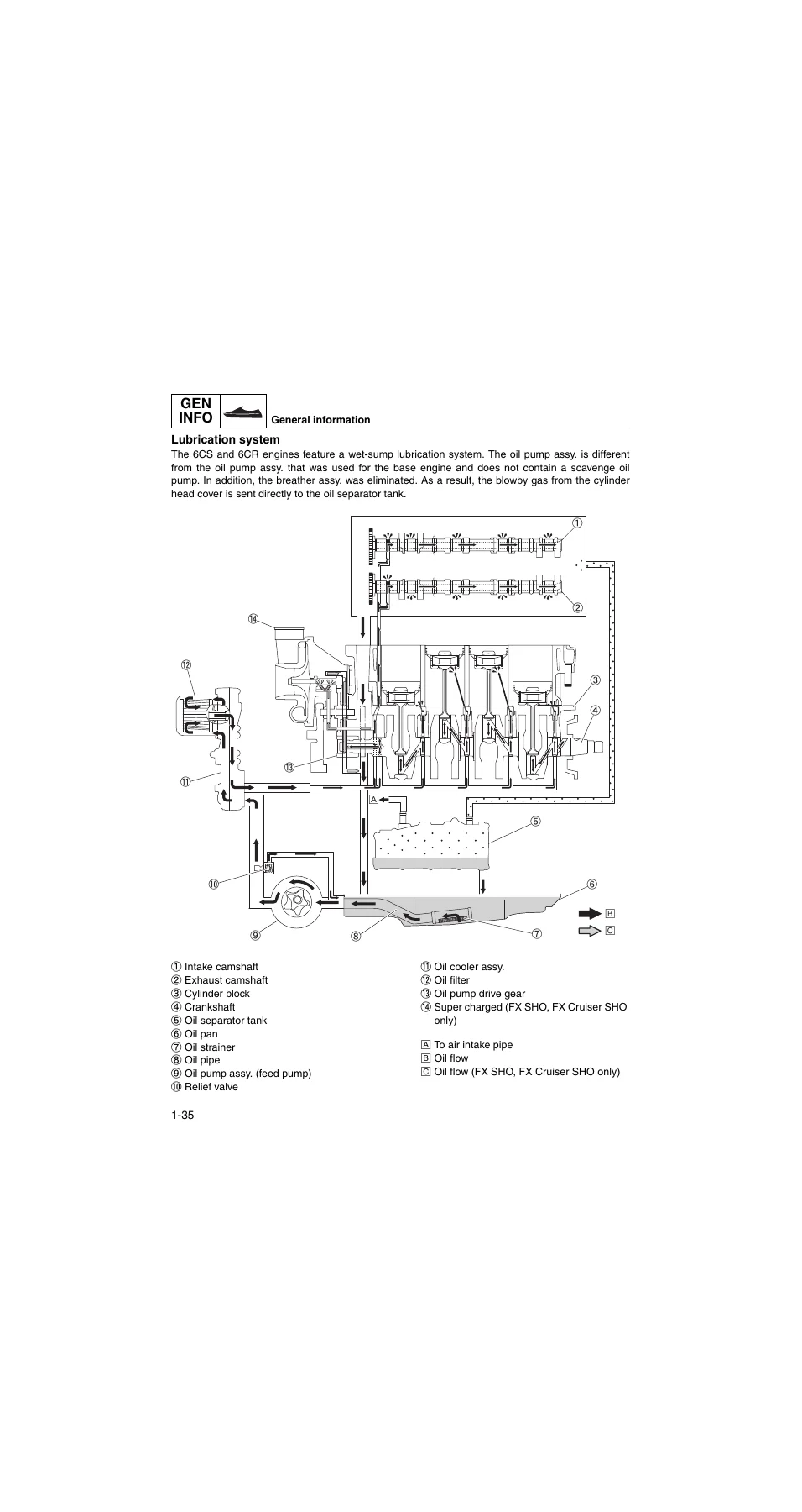
Lubrication systemp. 40
Hose routing (FX SHO, FX Cruiser SHO)p. 41
Hose routing (FX HO, FX Cruiser HO)p. 42
Cooling water flowp. 43
+Specificationp. 45
+Model datap. 46
Model codep. 46
Dimensions and weightp. 46
Performancep. 46
Power unitp. 46
Jet pump unitp. 47
Fuel and oil requirementp. 47
Battery requirementp. 48
+Fuel system technical datap. 48
+Power unit technical datap. 49
Power unitp. 49
Cylinder head assy.p. 49
Crankcase assy.p. 51
+Jet pump unit technical datap. 53
+Electrical technical datap. 53
Ignition systemp. 53
Charging systemp. 54
Control systemp. 54
Fuel systemp. 56
Starting systemp. 56
Meter systemp. 57
+Specified tightening torquep. 58
Fuel systemp. 58
Power unitp. 58
Jet pump unitp. 61
Electrical systemp. 61
Hull and hoodp. 61
Torque wrench reading (setting value)p. 63
General tightening torquep. 63
+Cable and hose routingp. 64
Starboard bow viewp. 64
Top viewp. 65
Port viewp. 67
+Maintenancep. 69
Maintenance interval chartp. 70
+Periodic servicep. 71
Jet thrust nozzle angle checkp. 71
Jet thrust nozzle angle adjustmentp. 71
Steering master checkp. 71
Shift cable and reverse gate checkp. 72
Shift cable adjustmentp. 72
Q.S.T.S. mechanism checkp. 72
Q.S.T.S. rod adjustmentp. 73
Fuel tank checkp. 73
Water separator checkp. 73
Spark plug checkp. 74
Engine oil level checkp. 74
Engine oil replacementp. 75
Oil filter replacementp. 76
Trolling speed checkp. 76
Nut and bolt checkp. 76
Valve clearance measurementp. 76
Impeller checkp. 78
Water inlet strainer checkp. 78
Battery checkp. 78
Bilge strainer checkp. 79
Electric bilge pump strainer checkp. 79
Drain plug checkp. 80
Throttle valve lubrication (FX SHO, FX Cruiser SHO)p. 80
Throttle valve lubrication (FX HO, FX Cruiser HO)p. 80
Q.S.T.S. cable (handlebar end) lubricationp. 81
Q.S.T.S. cable (converter end) and Q.S.T.S. rod joint lubricationp. 81
Nozzle pivot bolt and steering cable lubricationp. 81
Steering cable and steering cable joint lubricationp. 81
Shift lever assy., shift cable, and shift cable joint lubricationp. 81
Intermediate housing lubricationp. 82
+Fuel systemp. 83
Air filter case and fuel hose (FX SHO, FX Cruiser SHO)p. 84
+Air filter case and fuel hose (FX HO, FX Cruiser HO)p. 86
Fuel hose disconnectionp. 88
Fuel pressure measurementp. 88
Fuel hose disassemblyp. 89
Air filter element checkp. 89
Fuel hose assemblyp. 89
Fuel injector (FX SHO, FX Cruiser SHO)p. 91
+ETV and fuel injector (FX HO, FX Cruiser HO)p. 92
ETV check (FX HO, FX Cruiser HO)p. 93
Fuel injector checkp. 93
Fuel rail and injector installationp. 93
+Fuel tank and fuel pump module assy.p. 95
Fuel pump module removalp. 97
Fuel sender removalp. 97
Fuel pump module checkp. 97
Check valve checkp. 97
Fuel filler cap checkp. 98
Fuel sender installationp. 98
Fuel pump module installationp. 98
Fuel tank installationp. 99
+Power unitp. 102
+Engine unit (check and adjustment)p. 106
Compression pressure checkp. 106
Engine unit (FX SHO, FX Cruiser SHO)p. 107
Engine unit (FX HO, FX Cruiser HO)p. 108
Exhaust manifold (FX SHO, FX Cruiser SHO)p. 109
Exhaust manifold (FX HO, FX Cruiser HO)p. 111
Engine unit and coupling cover (FX SHO, FX Cruiser SHO)p. 113
Engine unit and coupling cover (FX HO, FX Cruiser HO)p. 114
+Engine mountp. 115
Engine unit removal (FX SHO, FX Cruiser SHO)p. 116
Engine unit removal (FX HO, FX Cruiser HO)p. 120
Engine mount and damper checkp. 124
Engine unit installation (FX SHO, FX Cruiser SHO)p. 124
Engine unit installation (FX HO, FX Cruiser HO)p. 130
+Mufflerp. 136
Exhaust pipe disassemblyp. 137
Exhaust pipe assemblyp. 137
Wiring harness assy. (FX SHO, FX Cruiser SHO)p. 138
Wiring harness assy. (FX HO, FX Cruiser HO)p. 139
+Electrical boxp. 140
Starter motor and wiring harness assy. removal (FX SHO, FX Cruiser SHO)p. 142
Starter motor and wiring harness assy. removal (FX HO, FX Cruiser HO)p. 143
Thermostat checkp. 144
Starter motor and wiring harness assy. installation (FX SHO, FX Cruiser SHO)p. 144
Starter motor and wiring harness assy. installation (FX HO, FX Cruiser HO)p. 145
Air cooler and supercharger assy.p. 147
Intake assy. (FX SHO, FX Cruiser SHO)p. 150
Intake assy. (FX HO, FX Cruiser HO)p. 152
+ETV and intake manifold (FX SHO, FX Cruiser SHO)p. 153
Air cooler check (FX SHO, FX Cruiser SHO)p. 154
Supercharger check (FX SHO, FX Cruiser SHO)p. 154
ETV check (FX SHO, FX Cruiser SHO)p. 154
Intake assy. installation (FX SHO, FX Cruiser SHO)p. 154
Intake manifold installation (FX HO, FX Cruiser HO)p. 155
Oil level pipe installation (FX SHO, FX Cruiser SHO)p. 156
Supercharger installation (FX SHO, FX Cruiser SHO)p. 157
Air cooler, air cooler intake hose, and boost pipe installation (FX SHO, FX Cruiser SHO)p. 157
Oil cooler and oil pump assy. (FX SHO, FX Cruiser SHO)p. 160
Idle gear assy. and drive gear assy. (FX SHO, FX Cruiser SHO)p. 162
+Oil cooler, oil pump assy. and drive gear (FX HO, FX Cruiser HO)p. 163
Oil pump assy., idle gear assy., and drive gear assy. removal (FX SHO, FX Cruiser SHO)p. 165
Oil pump assy. and oil pump drive gear removal (FX HO, FX Cruiser HO)p. 165
Oil cooler assy. checkp. 165
Oil pump assy. checkp. 166
Idle gear check (FX SHO, FX Cruiser SHO)p. 166
Drive gear assy. check (FX SHO, FX Cruiser SHO)p. 166
Drive gear assy., idle gear assy., and oil pump assy. installation (FX SHO, FX Cruiser SHO)p. 166
Oil pump drive gear and oil pump assy. installation (FX HO, FX Cruiser HO)p. 167
Cylinder head coverp. 169
Camshaft (FX SHO, FX Cruiser SHO)p. 170
+Camshaft (FX HO, FX Cruiser HO)p. 172
Camshaft removalp. 174
Camshaft sprocket removalp. 175
Camshaft checkp. 175
Camshaft journal oil clearance checkp. 176
Timing chain tensioner checkp. 177
Camshaft sprocket installationp. 177
Camshaft installationp. 178
Valve clearance adjustmentp. 180
Valve pad selection tablep. 183
Cylinder headp. 184
+Valve and valve springp. 185
Cylinder head disassemblyp. 186
Cylinder head checkp. 186
Valve spring checkp. 186
Valve checkp. 187
Valve guide checkp. 187
Valve guide removalp. 188
Valve guide installationp. 188
Valve seat checkp. 189
Valve seat refacingp. 189
Cylinder head assemblyp. 191
Cylinder head installationp. 193
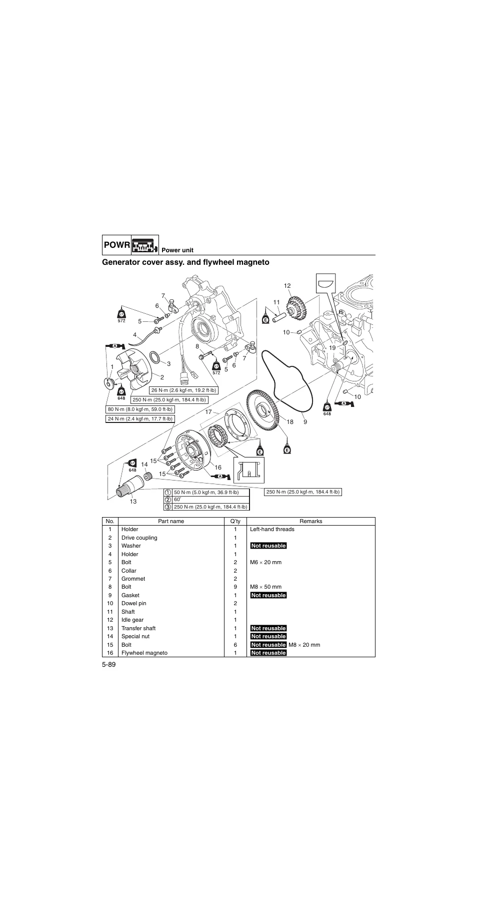
Generator cover assy. and flywheel magnetop. 194
+Generator coverp. 196
Drive coupling removalp. 197
Flywheel magneto removalp. 197
Generator cover assy. disassemblyp. 199
Starter clutch operation checkp. 199
Generator cover assy. assemblyp. 200
Flywheel magneto installationp. 201
Drive coupling installationp. 204
Cylinder block and electrical part (FX SHO, FX Cruiser SHO)p. 205
Cylinder block and electrical part (FX HO, FX Cruiser HO)p. 207
+Oil separator tank and oil panp. 209
Anode checkp. 211
Oil pan assemblyp. 211
Oil level pipe installation (FX HO, FX Cruiser HO)p. 211
Oil separator tank cover installationp. 212
+Crankcase, connecting rod, and pistonp. 213
Crankcase disassemblyp. 215
Connecting rod and piston removalp. 215
Crankcase checkp. 216
Cylinder block checkp. 216
Piston checkp. 216
Piston clearance checkp. 216
Piston ring checkp. 216
Piston pin checkp. 217
Connecting rod checkp. 218
Crankshaft checkp. 218
Crankshaft pin oil clearance checkp. 218
Connecting rod big end side clearance checkp. 219
Connecting rod bearing selectionp. 220
Crankshaft journal oil clearance checkp. 221
Crankshaft bearing selectionp. 222
Connecting rod and piston installationp. 223
Crankcase assemblyp. 225
+Jet pump unitp. 227
Intake grate and ride platep. 228
+Jet pump unitp. 229
Jet pump unit removalp. 231
Jet pump unit installationp. 232
Reverse gatep. 234
Nozzle and nozzle ringp. 235
Impeller housing and impeller duct assy.p. 236
+Impeller, drive shaft, and impeller ductp. 237
Impeller duct assy. disassemblyp. 238
Impeller housing checkp. 239
Drive shaft checkp. 239
Impeller duct assy. assemblyp. 239
Impeller duct, impeller housing, and nozzle installationp. 241
Transom plate and hosesp. 242
+Bilge and hosesp. 244
Bilge strainer checkp. 246
Electric bilge pump strainer checkp. 246
Transom plate installationp. 246
+Intermediate housingp. 247
Intermediate housing assy. removalp. 249
Intermediate housing assy. disassemblyp. 249
Intermediate housing assy. assemblyp. 250
Intermediate housing assy. installationp. 251
+Electrical systemp. 252
+Electrical componentsp. 254
Engine (FX SHO, FX Cruiser SHO)p. 254
Engine (FX HO, FX Cruiser HO)p. 255
Deck and hullp. 256
Electrical boxp. 257
ECM circuit diagramp. 258
ECM coupler layoutp. 260
+Electrical analysisp. 262
Electrical component check using the YDISp. 262
Power supply to the ECMp. 262
Peak voltage measurementp. 262
+Ignition systemp. 263
Ignition spark checkp. 263
Ignition coil checkp. 264
Pickup coil checkp. 264
+Charging systemp. 265
Stator coil checkp. 265
Rectifier regulator checkp. 266
+Control systemp. 267
Oil pressure switch checkp. 267
Thermoswitch checkp. 268
Thermo sensor checkp. 269
Engine temperature sensor checkp. 270
Intake air temperature sensor checkp. 270
Intake air pressure sensor checkp. 271
Knock sensor checkp. 272
TPS checkp. 272
ETV circuit continuityp. 274
APS checkp. 274
APS circuit continuityp. 275
ETV relay checkp. 276
Cam position sensor checkp. 277
Slant detection switch checkp. 278
Steering sensor checkp. 278
Reverse sensor checkp. 279
Right handlebar switch checkp. 279
ECM checkp. 280
Earth plate checkp. 281
Electric bilge pump checkp. 281
+Fuel systemp. 282
Fuel injector checkp. 282
Fuel pump module checkp. 282
+Starting systemp. 283
Left handlebar switch assy. checkp. 283
Main and fuel pump relay checkp. 284
Starter relay checkp. 285
+Starter motorp. 286
Starter motor operationp. 287
Armature checkp. 287
Brush holder checkp. 288
+Remote control systemp. 288
Remote control transmitter checkp. 288
Remote control receiver checkp. 290
Transmitter registrationp. 290
+Indication systemp. 291
Multifunction meter checkp. 291
Multifunction meter operation button checkp. 292
Compass display check (FX Cruiser SHO)p. 292
Air temperature display check (FX Cruiser SHO)p. 293
Water temperature display check (FX Cruiser SHO)p. 293
Speed sensor check (FX Cruiser SHO)p. 293
Speed sensor check (FX HO, FX Cruiser HO, and FX SHO)p. 294
Fuel level meter display and fuel level warning indicator checkp. 294
Check engine warning indicator checkp. 295
Diagnostic display checkp. 295
Oil pressure warning indicator checkp. 296
Engine overheat warning indicator checkp. 296
Buzzer checkp. 297
+Hull and hoodp. 298
Steering pad and handlebar coverp. 300
Handlebar and handlebar switch assy.p. 301
+Left handlebar switch assy. and throttle lever assy.p. 303
Cable and lead routingp. 304
Handlebar assy. installationp. 304
Front hoodp. 307
Multifunction meterp. 309
+Side coverp. 311
Side cover removalp. 312
Side cover installationp. 312
Center coverp. 313
Steering master assy.p. 315
+Steering masterp. 317
Steering shaft checkp. 319
Steering arm assy. installationp. 319
+Steering cable and speed sensor leadp. 320
Steering cable installation (steering master end)p. 323
Steering cable installation (jet pump end)p. 323
Shift cable installation (shift lever end)p. 324
Q.S.T.S. cable installation (Q.S.T.S. converter end)p. 324
Seat and handgripp. 326
+Ventilation hose and water separatorp. 328
Cooling water pilot outlet installationp. 330
Ventilation hose installationp. 330
+Exhaust systemp. 331
Exhaust system installationp. 333
+Rear sectionp. 334
Spout installationp. 337
Reboarding step assy. installationp. 337
Deck and hullp. 338
+Troubleshootingp. 341
+YDISp. 342
Functionp. 342
Basic componentsp. 344
Connecting the communication cable to the watercraftp. 345
+Engine unit troubleshootingp. 346
Using the YDIS for engine unit troubleshootingp. 346
Diagnostic code tablep. 348
Diagnostic code and checking stepp. 349
Engine unit troubleshooting (diagnostic code not detected)p. 355
+Appendixp. 361
+Wiring diagramp. 362
How to use the wiring diagramp. 362
FX SHO, FX Cruiser SHOp. 362
FX HO, FX Cruiser HOp. 366
Across 367 pages, the manual walks a technician through every major system on the FX platform — from the 4-stroke, 1812 cm³, DOHC, 16-valve engine with electronic fuel injection, through the jet pump unit and reverse gate assembly, out to the hull, hood, steering and Q.S.T.S. systems. It carries the factory torque values, wear limits, clearances, adjustment specifications, and diagnostic codes needed to do the work correctly rather than approximately.
What This 2012 Yamaha WaveRunner Service Manual Enables You To Do
- Diagnose electronic control faults using the ECM diagnostic code table and step-by-step checks for the ignition, charging, fuel, and sensor systems.
- Remove and reinstall the complete engine unit, disconnect and reconnect the drive coupling, and set shim clearances to specification.
- Rebuild the top end — cylinder head, camshafts, valve clearance adjustment, valve pad selection and valve seat refacing.
- Rebuild the bottom end — crankcase, connecting rod bearings (with colour-code selection), pistons, rings, and crankshaft journal oil clearance.
- Service the fuel system including the fuel injectors, ETV, fuel rail, fuel tank, and fuel pump module.
- Rebuild the jet pump unit and intermediate housing — impeller, drive shaft, oil seals, ball bearings, and driven coupling.
- Adjust jet thrust nozzle angle, steering master, shift cable, reverse gate, and Q.S.T.S.
- Perform all scheduled maintenance from the interval chart, using the correct grease, sealant, and thread-locking agent at each step.
- Trace wiring faults directly from the model-specific wiring diagrams in the appendix.
Model Coverage & Identification
This manual covers four 2012 Yamaha WaveRunner models, split across two hull series and two engine designations:
- FX HO — FB1800, engine 6CR, primary I.D. starting F2T: 800101
- FX Cruiser HO — FB1800A, engine 6CR, primary I.D. starting F2T: 800101
- FX SHO — FA1800, engine 6CS, primary I.D. starting F2S: 800101
- FX Cruiser SHO — FA1800A, engine 6CS, primary I.D. starting F2S: 800101
Engine serial numbers begin at A6CS:1000001 for F2S (FX SHO / FX Cruiser SHO) and B6CR:1000001 for F2T (FX HO / FX Cruiser HO). The FX SHO and FX Cruiser SHO run a supercharged 6CS engine with a 17.6° pitched impeller, while the FX HO and FX Cruiser HO run a naturally aspirated 6CR engine with a 15.3° pitched impeller; both share the NanoXcel hull and deck and the 4-stroke, L4, DOHC, 16-valve 1812 cm³ powerplant.
Why the Factory Procedures Matter
On an FX-series WaveRunner, a repair that is close but not exact usually shows up later — an oil clearance that is a few hundredths of a millimetre out, a valve pad picked by eye, a coupling shim guessed at, or an ETV not re-checked after service. This manual gives the correct value, the correct sequence, and the correct tool at each step: the two-stage and three-stage torque sequences, the bearing colour-code selection tables, the shim thickness ranges, the diagnostic code-to-cause mapping, and the specific sealant and thread-locking agent symbols stamped on each exploded diagram. That is the difference between a repair that lasts the season and one that returns to the bench.
Instant PDF Delivery — No Shipping, Print What You Need
The file is delivered as an instant PDF download immediately after purchase — nothing is shipped and nothing is printed on our side. Open it on any laptop, tablet, or phone, or print only the pages for the job in front of you and keep the clean copy in the shop for the next one. Whether you are diagnosing an ETV fault, rebuilding a supercharger, setting the drive coupling, or working through the whole engine unit, this 2012 Yamaha WaveRunner FX HO, FX Cruiser HO, FX SHO, and FX Cruiser SHO Service Manual gives you the workshop-grade reference for the job.

Reviews
There are no reviews yet.