
1998 Isuzu FSR FTR FVR Service Manual – 6HK1 Engine & Transmission Repair Book 3 of 3 (PDF)
Original price was: $59.95.$39.95Current price is: $39.95.
Complete 1998 Isuzu FSR, FTR and FVR commercial truck service manual covering 6HK1-TC 7.8L diesel engine overhaul, fuel injection, turbocharger, engine electrical, emission diagnosis, and Allison automatic plus MLD6Q manual transmission repairs. Book 3 of 3 – 476 pages, instant PDF download.
Description
Isuzu FSR FTR FVR Service Manual – Book 3 of 3 (1998)
This is the complete 1998 Isuzu FSR, FTR and FVR commercial truck service manual for vehicles equipped with the 6HK1-TC 7.8L diesel engine. Book 3 of 3 covers the engine and transmission/transaxle sections in full – everything from engine cooling and electrical through diesel fuel injection, emission diagnostics, turbocharger service, and both the Allison automatic and MLD6Q manual transmission overhaul procedures. Published by Isuzu Motors America, Inc. with an information cutoff date of 12/1/97, this is the same reference material used in professional service bays for diagnosing, repairing and overhauling these medium-duty trucks.
File Details
- Manual Type: Service Manual – Book 3 of 3
- Brand: Isuzu
- Covered Models: FSR, FTR, FVR
- Engine: 6HK1-TC (7.8L / 475 CID)
- Language: English
- Page Count: 476
- File Format: PDF
- Publisher: Isuzu Motors America, Inc.
- Publication Date: 1998 (information cutoff 12/1/97)
Chapters Covered
- Engine
- Transmission/Transaxle
Engine – Cooling, Electrical & On-Vehicle Service
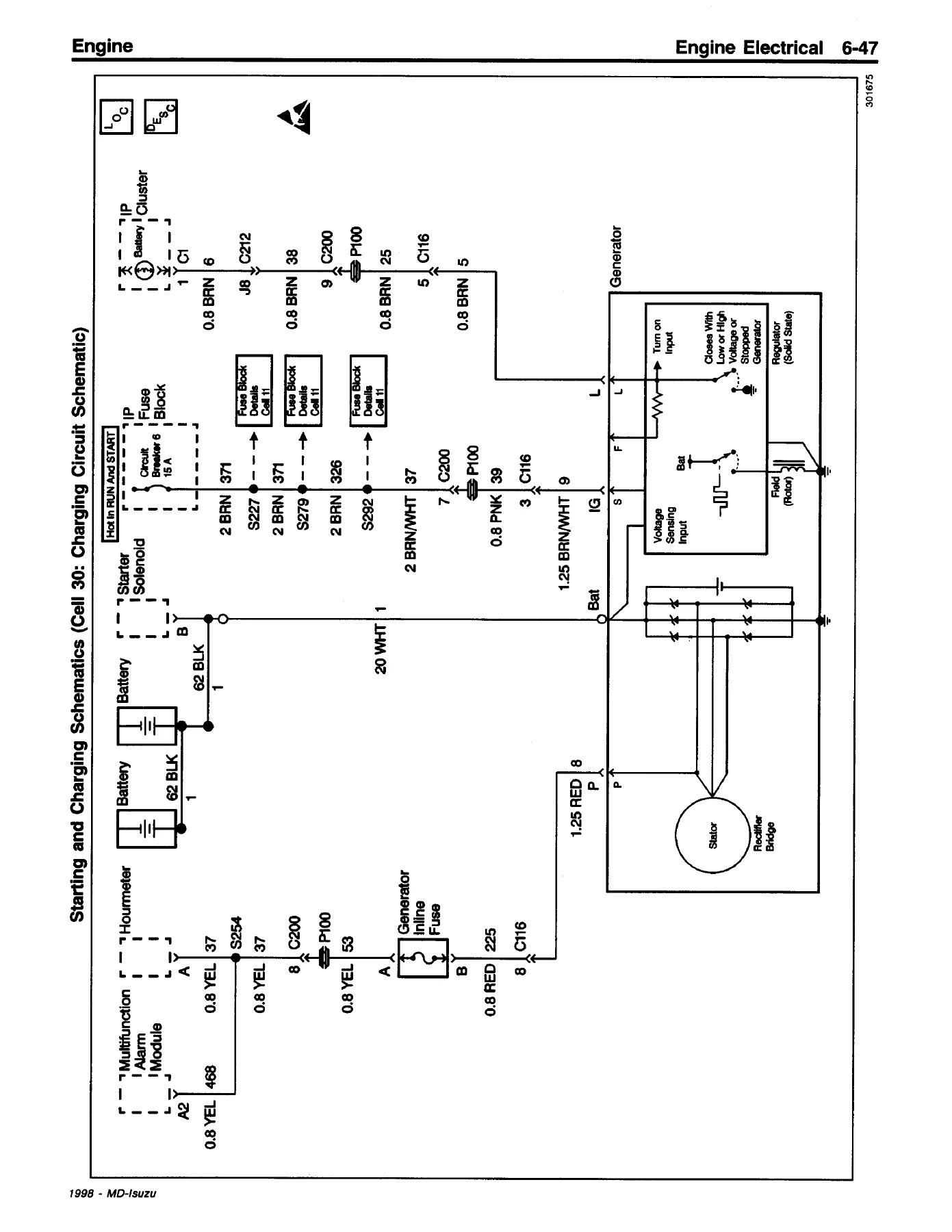
The engine section opens with full cooling system specifications, diagnostic information and repair procedures. You get thermostat diagnosis with the water-heating test, fan clutch diagnosis covering noise, looseness, silicone fluid leaks and engine overheating, coolant concentration testing using J 26568 or J 23688, and cooling system leak testing with J 24460-01. Repair instructions walk through draining and filling, flushing, radiator cleaning, surge tank replacement for diesel models, coolant recovery reservoir and pipe replacement, upper and lower radiator hose replacement, fan blade and fan clutch replacement with the J 38425 fan hub wrench, thermostat housing and thermostat replacement, water pump replacement and overhaul using J 1859-A and J 28509-A, coolant level sensor replacement, engine coolant temperature sensor replacement, fan shroud replacement, radiator replacement, and radiator lower mounting panel replacement. The engine electrical chapter covers battery testing and charging system diagnostics, starter motor overhaul and inspection, generator overhaul, battery cable replacement, and ground strap service – all with the fastener tightening specifications you need.
Engine Controls – 7.8L
This chapter delivers the full engine control system schematic and routing diagrams, component locator views, connector end views for every sensor and switch, and a detailed diagnostic section. You get the Engine Control Module (ECM) pin assignments for both the 40-pin and 80-pin connectors, a chart of ECM input/output, and troubleshooting procedures for the common rail system. The engine controls coverage includes the accelerator sensor, engine coolant temperature sensor, engine oil pressure gauge sender, engine speed sensor, fuel pressure sensor, fuel temperature sensor, injection pump speed sensor, turbo boost pressure sensor, and more. Diagnostic trouble code charts and scan data values are included for the 7.8L engine management system.
Engine Exhaust & Exhaust Brake
The exhaust chapter provides fastener tightening specifications, diagnostic information for vibration, rattling, restricted exhaust, exhaust noise, and detailed exhaust brake diagnosis covering conditions like continuously on, engine overheats or loses power, does not operate, slow to operate, weak braking action, and will not turn off. Repair instructions include exhaust system replacement, exhaust clamps replacement for wide band, U-bolt and slip joint types, accelerator pedal switch replacement, clutch pedal switch replacement, exhaust brake actuator control valve replacement, actuator stop peg replacement, ball joint replacement, exhaust pipe replacement for front and rear sections, muffler replacement and tail pipe replacement. The exhaust brake operation description explains the system components and how the air cylinder, control valve and manifold valve work together.
Diesel Engine On-Vehicle Service (6A6)
This section covers all the engine work you can perform with the engine still in the truck. It includes valve rocker arm cover removal and installation, valve rocker arm and camshaft service, valve stem seal and valve spring replacement using J 36022, J 43267 and J 43263, intake manifold removal and installation with the tightening sequence, exhaust manifold service with flatness inspection, cylinder head removal and installation with the torque sequence and final torque step, crankshaft balancer and front cover oil seal replacement using J 39046, J 41220 and J 41221, oil pan service, oil pump repair, crankshaft rear oil seal replacement, camshaft removal and installation with timing mark alignment, connecting rod and piston service, crankshaft main bearing and crankshaft procedures, flywheel and flywheel ring gear service, engine mount inspection and replacement for front and rear, and complete engine removal and installation. The general engine specifications table covers the 6HK1-TC firing order, valve clearance, oil capacity, oil pressure, compression and more.
Diesel Engine Overhaul (6A6B)
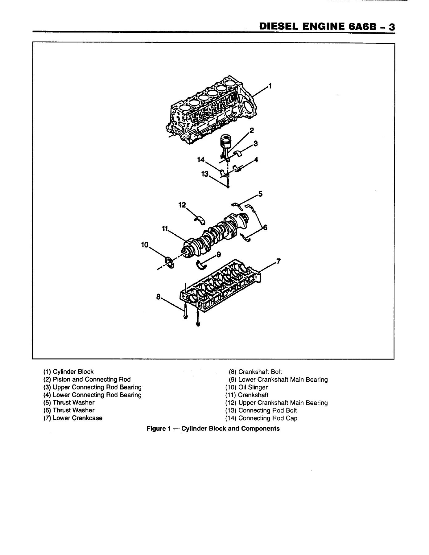
The full engine overhaul section takes you through disassembly of the engine, accessory removal, cleaning, draining, flywheel removal, intake and exhaust manifold removal, glow plug removal, fuel injection pump removal, thermostat housing removal, valve rocker arm cover removal, valve rocker arm and camshaft assembly removal, cylinder head assembly removal, water pump removal, crankshaft balancer removal, front cover removal, oil pan removal, flywheel housing removal, oil pump removal, piston and connecting rod removal, cylinder liner removal, crankshaft removal and oil jet removal. Cleaning, inspection and repair procedures cover the engine block, crankshaft inspection, crankshaft timing gear inspection and replacement, oil pump inspection and repair, idler gear inspection and replacement, piston and connecting rod assemblies, piston selection, connecting rod inspection, cylinder liner selection, cylinder head and valve train components, camshaft inspection, cylinder head cleaning, valve seat reconditioning, valve guide replacement, valve seat replacement, valve lapping, and injection nozzle sleeve replacement. Assembly of the engine covers oil jet installation, oil filter installation, crankshaft installation with bearing clearance measurement, front cover installation, water pump installation, cylinder liner installation, piston and connecting rod installation, oil pump installation, oil pan installation, cylinder head installation, camshaft installation, valve train installation, valve adjustment, intake manifold installation, exhaust manifold installation, glow plug installation, fuel injectors and fuel injection pump installation, flywheel installation, and engine accessory installation. The specifications section includes general engine specifications, engine specifications with production and service limit values, and a full fastener tightening specifications table.
Water Pump Overhaul (6B1B)
This short section covers water pump disassembly, inspection and repair, pump spindle interference measurements for the shaft to pulley center and shaft to impeller, assembly procedures including bearing and spacer installation, front seal installation, snap ring installation, dust thrower installation, pulley installation, seal unit installation with the specified seal height of 11.0–11.6 mm, and impeller installation. The specifications table gives the pump spindle interference values and special tools list.
Fuel System & Diesel Fuel Injection (6C / 6C2)
The fuel system section points to the appropriate Diesel Fuel Injection and Engine Emission and Electrical Diagnosis service manuals. The diesel fuel injection chapter covers the common rail system in detail – system outline, composition, description and operation, various controls including fuel pilot injection control, fuel injection amount control, fuel injection timing control and fuel injection pressure control, fuel injection rate control covering main injection, pilot injection and split injection, and the fuel injection system operation with a complete system schematic. On-vehicle service covers fuel injection pump removal and installation with TDC alignment and timing mark procedures, fuel injector removal and installation with clamp bolt torque and injection pipe torque, and bleeding the fuel system using the primer pump and fuel filter eye bolt. The specifications section lists all the important tightening torques for the injection system – injection pipe sleeve nuts, high pressure fuel pipe sleeve nuts, common rail pressure sensor, flow damper, fuel temperature sensor and fuel return pipe eye bolts.
Diesel Electrical (6D6)
The diesel electrical section covers glow plugs, starting procedure, glow plug operation, diagnosis of the glow plug relay, glow plug check using J 39200 and J 35590, buss bar check, and on-vehicle service for glow plug relay and glow plugs. The specifications table covers battery top post terminal nut, buss bar to glow plug nut, and glow plug to cylinder head torque values. Special tools are listed.
Engine Emission & Electrical Diagnosis (6E)
This is the largest diagnostic chapter in Book 3. It opens with notes for working on electrical items, symbols and abbreviations, parts for electrical circuits, and then dives into strategy-based diagnostics. You get the full On-Board Diagnostic (OBD) system explanation including DTC types, freeze frame and failure records, the Data Link Connector (DLC) location, and how to read diagnostic trouble codes using a Tech 2 or other scan tool. The ECM section covers the appearance of the ECM, caution plate, 40-pin and 80-pin connector details, ECM input/output chart and connector pin assignments. The troubleshooting section lists diagnostic trouble codes with detailed flow charts for each – crank position sensor error, pump position sensor error, abnormal common rail pressure, common rail pressure sensor output fixed, Q-adjusted data error, water temperature sensor error, fuel temperature sensor error, atmospheric temperature sensor error, accelerator sensor error, atmospheric pressure sensor error, starter switch abnormal, flow damper activated, TWV side disconnected, TWV driving system errors, injection pump non-pressure supply, pressure limiter activation, PCV coil or harness issues, PCV relay system error, main relay system error, boost pressure sensor error, high and low boost pressure abnormal, and overrun judgment. Symptom-based diagnostics cover engine hunting, startup failure, white smoke, black smoke, lack of power, surging and hesitation, engine stall, engine does not stop, idle control error, high idle engine speed, and more. Typical scan data values are provided for the engine parameters.
Turbocharger (6J)
The turbocharger chapter provides a general description of how the turbocharger and charge air cooler work together, on-vehicle service for the charge air cooler and turbocharger, disassembly and assembly procedures, inspection of compressor blades and housing, and measurement of bearing radial clearance and compressor end play. Repair instructions cover turbocharger removal and installation with proper gasket orientation, oil drain tube and oil feed line service, and the critical pre-lubrication of the turbocharger bearings before startup. Fastener tightening specifications and special tools are included.
Transmission/Transaxle – Manual Transmission Medium Duty
The manual transmission section covers specifications, lubrication specifications, diagnostic information and procedures for transmission jumps out of gear, sticking in gear, noisy in the gears, oil leak diagnosis, noisy bearings, noisy in all gears, and noisy in neutral with engine running. Repair instructions include shift cable replacement, shift cable adjustment, transmission oil change procedure, speedometer driven gear replacement, speedometer driven gear backlash adjustment, and transmission replacement. The description and operation section covers the MLD6Q six-speed transmission with constant mesh first and reverse gear, synchronized gears, remote shift control with two cables, and power takeoff capability. Overhaul information points to the MLD6Q manual transmission overhaul section.
Automatic Transmission – Allison
The Allison automatic transmission section covers fastener tightening specifications and fluid capacity specifications for the Allison AT 545. Diagnostic information and procedures cover shift speed too high, shift speed too low, low main pressure in all ranges, low main pressure in first gear, intermittent buzzing noise, excessive creep in first and reverse gears, low lubrication pressure, fluid leaking into converter housing, transmission overheats in all ranges, high stall speed, low stall speed, rough shifting, excessive slip and clutch chatter only one range, dirty fluid, output shaft seal fluid leak, slips in all forward ranges, slips in fourth and reverse gear only, slips in reverse and first gear only, vehicle moves forward in neutral, vehicle moves backward in neutral, fluid out of fill tube or breather, and oil leak diagnosis. Repair instructions include parts cleaning and inspection, transmission oil pan and filter replacement, shift cable replacement, shift cable adjustment, transmission modulator replacement, transmission modulator cable adjustment, transmission oil level indicator tube replacement, transmission replacement, transmission oil checking procedure, external transmission oil filter replacement, transmission oil cooler line replacement, and flushing the transmission oil cooler and lines. The description and operation section explains the hydraulic torque converter, planetary gear train and hydraulic control system.
Clutch
The clutch section covers fastener tightening specifications, sealers and lubricants, diagnostic information for clutch slipping, clutch grabbing (chattering and grabbing), clutch rattle, clutch noisy and clutch noisy during engagement. Repair instructions include clutch pressure plate and clutch driven plate replacement using J 37367 clutch pilot aligner, and release bearing replacement. The description and operation section explains the clutch driving members, clutch driven members, clutch operating members and hydraulic clutch description.
Manual Transmission Overhaul (MLD6Q)
The MLD6Q manual transmission overhaul section provides a complete tear-down and rebuild guide. It covers transmission case disassembly, gearshafts disassembly, top gear shaft disassembly, mainshaft disassembly, lower quadrant box disassembly, upper quadrant box disassembly, upper quadrant box assembly, lower quadrant box assembly, gearshafts assembly, countershaft assembly, mainshaft assembly, top gear shaft assembly, and transmission case assembly. The specifications section lists capacities, fastener tightening specifications and special tools including J 22912-01, J 34827, J 35699 and J 35909.
Why This Isuzu FSR FTR FVR Service Manual Belongs in Your Shop
IMAGES PREVIEW
If you maintain, repair or overhaul Isuzu FSR, FTR or FVR trucks with the 6HK1-TC engine, this Book 3 of 3 service manual is the reference that keeps you from guessing. The 6HK1 is a 7.8L inline-six turbocharged diesel with a common rail fuel system, and the procedures in this manual are specific to that engine – the torque values, the clearances, the diagnostic trouble code charts, the timing marks, the seal installation depths and the tool numbers are all there. Whether you are adjusting valve clearance, replacing a water pump, diagnosing a no-start condition with the Tech 2, overhauling the cylinder head, setting up the injection pump timing, or rebuilding the Allison AT 545 automatic transmission, this manual gives you the step-by-step procedures and the specifications that the factory expects you to follow. The emission and electrical diagnosis chapter alone is worth the price – it covers every DTC the 6HK1 engine control system can set, with flow charts that tell you exactly what to check and in what order. The transmission sections cover both the MLD6Q six-speed manual and the Allison AT 545 automatic, so you are covered regardless of which transmission your truck has. The clutch section is included as well. This is a PDF download, so you get instant access after checkout – no shipping, no waiting. Open it on any device, print the pages you need for the job, and keep the digital copy on hand for quick reference. The manual is fully printable and works on phones, tablets, laptops and desktop computers.
Reviews
There are no reviews yet.