Description
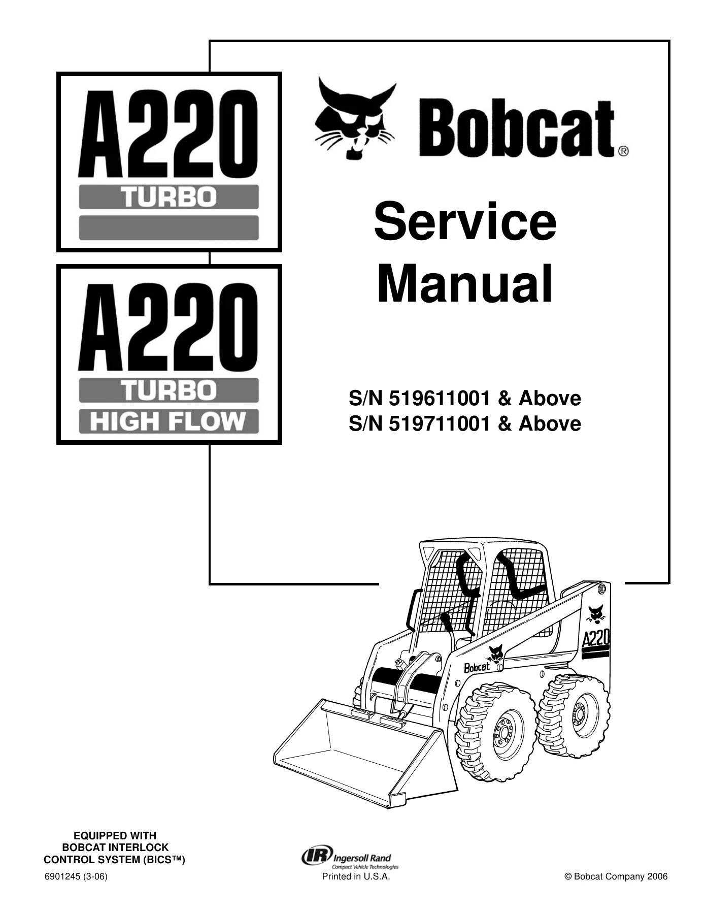
2006 Bobcat A220 Turbo & High Flow Service Manual 6901245 PDF
The 2006 Bobcat A220 Turbo & High Flow Service Manual 6901245 PDF is an extensive workshop reference for servicing, adjusting, diagnosing and repairing the Bobcat A220 Turbo and A220 Turbo High Flow loader. The cover identifies coverage for S/N 519611001 & Above and S/N 519711001 & Above, with the machines equipped with the Bobcat Interlock Control System (BICS™). At 980 PDF pages, this manual goes far beyond routine operator maintenance and follows the loader through individual components, systems, test procedures, removal and installation work, disassembly and assembly, troubleshooting and specification data.
The manual is written for the Bobcat loader mechanic and contains the servicing and adjustment procedures needed for the loader and its component parts and systems. It is especially useful when a repair requires more than a basic maintenance check: hydraulic cylinders can be taken through checking, removal, parts identification, disassembly and assembly; hydrostatic components receive similarly detailed treatment; electrical sections include wiring schematics, controllers and diagnostic service codes; and the engine chapter includes component testing and extensive engine reconditioning procedures.
File Details
- Manual type: Service Manual
- Brand: Bobcat
- Models: A220 Turbo, A220 Turbo High Flow
- Serial coverage: S/N 519611001 & Above; S/N 519711001 & Above
- Document number: 6901245 (3-06)
- Date: 2006
- Language: English
- Pages: 981
- File format: PDF
A220 Turbo and High Flow Workshop Coverage
This Bobcat A220 service manual brings mechanical, hydraulic, hydrostatic, electrical, engine and HVAC work into one technical reference. The loader uses a Deutz/BF4M1011F Turbo-Charged diesel engine, and the manual combines loader-specific service information with detailed engine repair and specification material. The hydraulic coverage is particularly substantial, including the standard hydraulic pump, dedicated high flow pump, control valve, select valve, relief valves, lift and tilt cylinders, steering cylinders, auxiliary circuits, Bob-Tach components and numerous hydraulic/hydrostatic schematics for different serial-number breaks and option combinations.
Serial-number distinctions are important throughout the document. The manual includes procedures and schematic variations for early and later machines, with individual hydraulic diagrams for standard, two-speed, High Flow and High Flow with two-speed configurations. Some procedures also identify specific serial breaks, such as the front auxiliary hydraulic coupler block beginning at S/N 519611124. This makes the 2006 Bobcat A220 Turbo & High Flow Service Manual 6901245 PDF useful when the correct procedure or circuit depends on the production version being serviced.
Chapters Covered
- Foreword – mechanic-oriented service scope and post-repair inspection points
- Safety Instructions – servicing precautions and fire prevention
- Serial Number Location – loader and engine serial-number identification
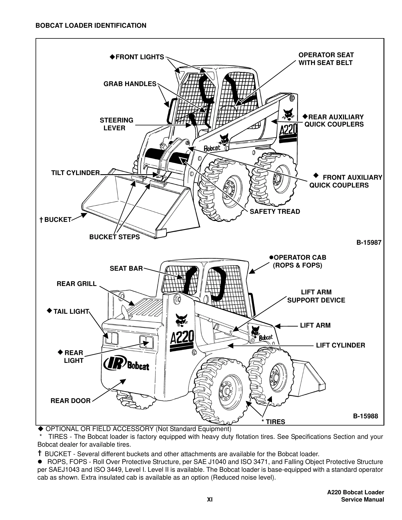
- Bobcat Loader Identification – major loader components and equipment locations
- Safety & Maintenance – lifting and blocking, lift arm support device, operator cab and remote start procedures
- Safety & Maintenance – service schedule, air cleaner, cooling system, fuel system and engine lubrication
- Safety & Maintenance – hydraulic/hydrostatic fluid and filter service, chaincase, fan gearbox and loader lubrication
- Safety & Maintenance – Bob-Tach and Power Bob-Tach inspection, tire maintenance, towing and transporting
- Hydraulic System – hydraulic system information and troubleshooting
- Hydraulic System – lift, tilt, steering and Power Bob-Tach cylinders
- Hydraulic System – hydraulic control valve, BICS™ valve components, spools, check valves and relief valves
- Hydraulic System – hydraulic fluid reservoir and hydraulic/hydrostatic filter
- Hydraulic System – hydraulic pump output checks, removal, parts identification, disassembly and assembly
- Hydraulic System – High Flow hydraulic pump testing, removal, disassembly and assembly
- Hydraulic System – main relief valve, lift arm by-pass control valve and select valve
- Hydraulic System – Power Bob-Tach blocks, rear auxiliary diverter valve and auxiliary pressure release
- Hydraulic System – front auxiliary hydraulic coupler block and serial-specific components
- Hydraulic/Hydrostatic Schematics – standard, High Flow and two-speed circuit configurations across multiple serial breaks
- Hydrostatic System – system information, replenishing valve function and troubleshooting chart
- Hydrostatic System – hydrostatic motors and two-speed motor service
- Hydrostatic System – hydrostatic motor carrier removal, disassembly and assembly
- Hydrostatic System – hydrostatic pump removal, separation, inspection, assembly and adjustments
- Hydrostatic System – charge pump, pump controller, neutral adjustment and system relief checks
- Hydrostatic System – hydraulic oil cooler removal and installation
- Drive System – brakes, chaincase, hubs and drive components
- Drive System – steering block and related drive-system service
- Main Frame – lift arms, operator cab, operator seats and seat bar
- Main Frame – control panel and controls, rear door and rear grill
- Main Frame – fuel tank and Power Bob-Tach components
- Electrical System Analysis – electrical system information, wiring schematics, fuses, relays and solenoid testing
- Electrical System Analysis – battery, alternator and starter service
- Electrical System Analysis – BICS™ system testing and troubleshooting
- Electrical System Analysis – Bobcat controllers and early Bobcat 2001 controller
- Electrical System Analysis – diagnostic service codes and code lists
- Electrical System Analysis – instrument panel, lights, speed sensor, steering solenoid and traction lock
- Electrical System Analysis – wheel position sensors and electrical/hydraulic controls reference
- Engine Service – engine components, tests and troubleshooting
- Engine Service – engine speed control, air cleaner, cooling components and radiator
- Engine Service – fuel system and fuel-injection components
- Engine Service – flywheel, housing, muffler and turbocharger-related service
- Engine Service – extensive engine reconditioning, inspection and assembly procedures
- Heating, Ventilation & Air Conditioning – system components and general A/C service guidelines
- Heating, Ventilation & Air Conditioning – compressor, condenser, evaporator and expansion valve
- Heating, Ventilation & Air Conditioning – evaporator/heater unit, heater coil, fan and heater valve
- Heating, Ventilation & Air Conditioning – basic and system troubleshooting, temperature and pressure checks
- Heating, Ventilation & Air Conditioning – R-134a charging, reclamation and regular maintenance
- Specifications – loader dimensions, performance, controls, capacities and tires
- Specifications – engine dimensions, clearances, wear limits and fuel-system data
- Specifications – loader torque values and general SAE and metric bolt torque
- Specifications – hydraulic connection tightening data and hydraulic fluid specifications
- Specifications – decimal and millimeter conversions
Together these chapters provide a working path from identifying the correct machine and observing service precautions through diagnosis, component removal, repair, adjustment and reassembly. The manual includes photographs and component illustrations throughout the procedures, exploded component identification drawings, hydraulic/hydrostatic schematics, electrical wiring information, troubleshooting charts, service-code information, maintenance schedules and detailed specification sections. It is therefore useful both for a specific repair and as a long-term technical reference for the A220 loader.
Diagnostics, Schematics and Repair Data
Diagnosis is integrated into several systems rather than being confined to a single troubleshooting chapter. Hydraulic troubleshooting addresses symptoms such as slow or irregular hydraulic action, lift-arm problems and relief-pressure issues. Hydrostatic troubleshooting covers drive loss, straight-line travel problems, overheating and low charge-pressure warnings. Electrical diagnosis includes battery, alternator and starter faults along with controller, BICS™ and diagnostic service-code information. The HVAC material adds its own troubleshooting procedures, electrical checks, refrigerant service and pressure/temperature information.
Complete PDF Bookmark Tree
Complete Bookmarks
The complete bookmarks in the “2006 Bobcat A220 Turbo & High Flow Service Manual 6901245 PDF” are as follows:
MAINTENANCE SAFETYp. 2
ALPHABETICAL INDEXp. 4
+CONTENTSp. 6
FOREWORDp. 7
+SAFETY INSTRUCTIONSp. 10
+SERIAL NUMBER LOCATIONp. 14
Loader Serial Numberp. 14
Engine Serial Numberp. 14
DELIVERY REPORTp. 15
BOBCAT LOADER IDENTIFICATIONp. 16
+SAFETY & MAINTENANCEp. 18
+LIFTING AND BLOCKING THE LOADERp. 20
+LIFT ARM SUPPORT DEVICEp. 22
Engaging The Lift Arm Support Devicep. 22
Disengaging The Lift Arm Support Devicep. 23
+OPERATOR CABp. 24
Raising The Operator Cabp. 24
Lowering The Operator Cabp. 25
Emergency Exitp. 26
+TRANSPORTING THE LOADERp. 28
+TOWING THE LOADERp. 30
Procedure For Non-Two-Speedsp. 30
Procedure For Two-Speedsp. 31
+REMOTE STARTp. 34
Procedure For Loader Without Attachment Control Harnessp. 34
Procedure For Loader With Attachment Control Harnessp. 35
Procedurep. 37
+SERVICE SCHEDULEp. 38
+AIR CLEANER SERVICEp. 40
Replacing Filter Elementp. 40
+ENGINE COOLING SYSTEMp. 42
Cleaning The Cooling Systemp. 42
+FUEL SYSTEMp. 44
Fuel Specificationsp. 44
Filling The Fuel Tankp. 44
Fuel Filterp. 45
Removing Air From The Fuel Systemp. 45
+ENGINE LUBRICATION SYSTEMp. 46
Checking Engine Oilp. 46
Replacing Oil And Filterp. 47
+HYDRAULIC/HYDROSTATIC SYSTEMp. 48
Checking And Adding Fluidp. 48
Hydraulic/Hydrostatic Filter Replacementp. 48
Replacing Hydraulic Fluidp. 49
Steering Filter Replacmentp. 50
+FINAL DRIVE TRANSMISSION (CHAINCASE)p. 52
Checking And Adding Oilp. 52
Replacing The Oilp. 52
+FAN GEARBOXp. 54
Checking And Adding Oilp. 54
+BOB-TACHp. 56
Inspection And Maintenancep. 56
+POWER BOB-TACH (OPTION)p. 58
Inspection And Maintenancep. 58
+LUBRICATING THE LOADERp. 60
+TIRE MAINTENANCEp. 62
Wheel Nutsp. 62
Tire Rotationp. 62
Tire Mountingp. 62
+HYDRAULIC SYSTEMp. 64
HYDRAULIC/HYDROSTATIC SCHEMATICSp. 68
+HYDRAULIC SYSTEM INFORMATIONp. 104
Troubleshootingp. 108
Tighten Proceduresp. 109
+CYLINDER (LIFT)p. 110
Checkingp. 110
Removal And Installationp. 110
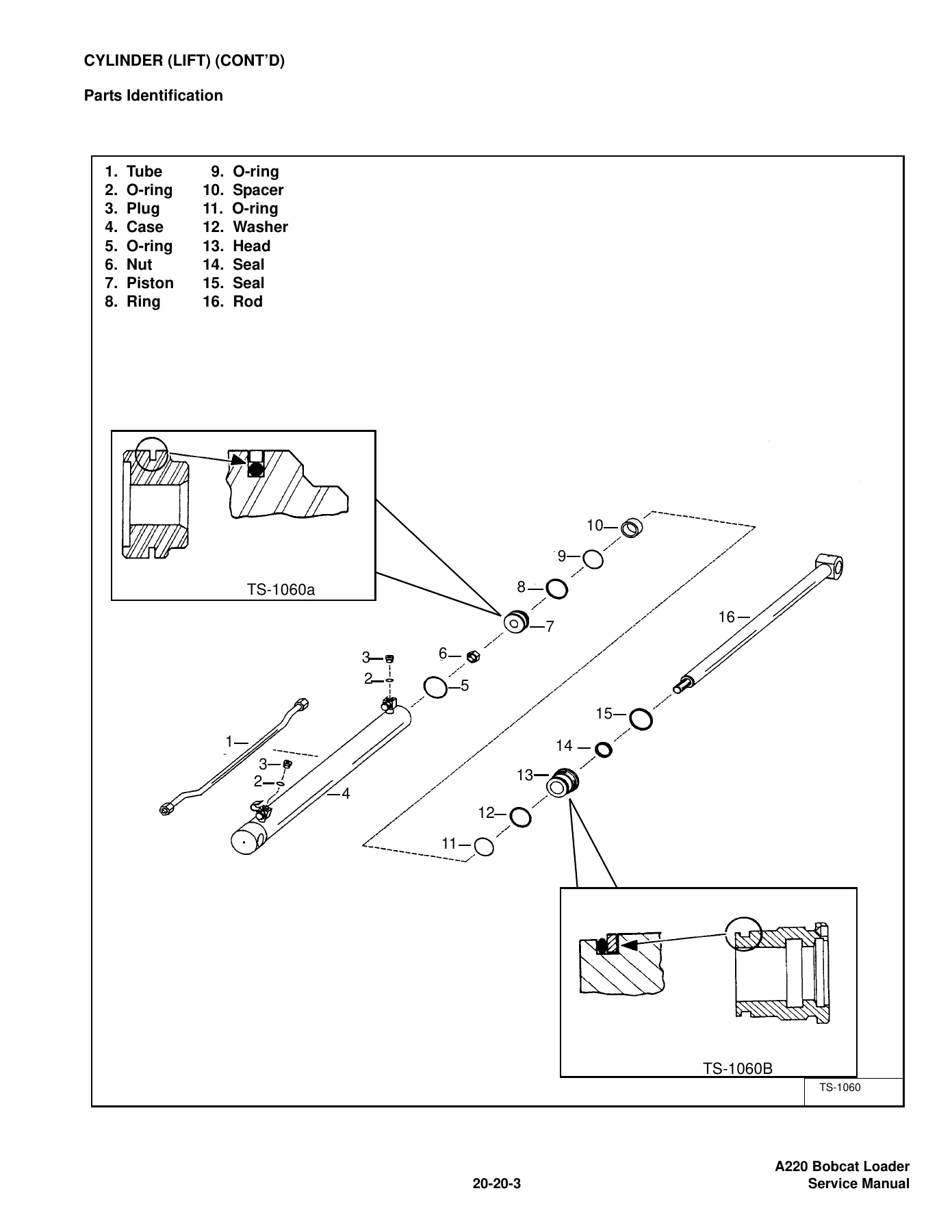
Parts Identificationp. 112
Disassemblyp. 113
Assemblyp. 114
+CYLINDER (TILT)p. 118
Checkingp. 118
Removal And Installationp. 118
Rod End Sealp. 119
Parts Identificationp. 121
Disassemblyp. 122
Assemblyp. 123
+CYLINDER (POWER BOB-TACH)p. 126
Checkingp. 126
Removal And Installationp. 127
Parts Identificationp. 128
Disassemblyp. 129
Assemblyp. 130
+CYLINDER (STEERING)p. 134
Removal (Front)p. 134
Removal (Rear)p. 137
+MAIN RELIEF VALVEp. 140
Checking The Main Relief Valve At Front Auxiliary Hydraulicsp. 140
Removal And Installationp. 141
Adjustmentp. 142
+HYDRAULIC CONTROL VALVEp. 144
Actuator Removal And Installation (In Loader)p. 144
Removal And Installationp. 146
Actuator Removal And Installation (Out Of Loader)p. 151
BICS™ Valve Removal And Installationp. 152
BICS™ Valve Lift Arm By-Pass Orifice Removal And Installationp. 153
BICS™ Valve Check Valve Removal And Installationp. 154
BICS™ Valve Lock Valve Removal And Installationp. 155
BICS™ Valve Solenoid Removal And Installationp. 156
BICS™ Valve Solenoid Testingp. 157
Identification Chartp. 158
Lift Base End Restrictorp. 159
Load Check Valvep. 159
Main Relief Valvep. 160
Port Relief Valvep. 161
Anti-Cavitation Valve/Port Relief Valvep. 162
Anti-Cavitation Valvep. 163
Lift Spool Removal And Installationp. 164
Tilt Spool Removal And Installationp. 165
Lift And Tilt Spool Disassembly And Assemblyp. 166
Auxiliary Spool Removal And Installationp. 167
Auxiliary Electric Solenoid Disassembly And Assemblyp. 167
Port-Auxiliary Section Disassemblyp. 169
Cleaning And Inspectionp. 169
+LIFT ARM BY-PASS CONTROL VALVEp. 170
Inspectingp. 170
Removal And Installationp. 170
Disassembly And Assemblyp. 171
+HYDRAULIC PUMPp. 172
Checking The Output Of The Auxiliary Pumpp. 172
Checking The Output Of The Steering Pumpp. 173
Removal And Installationp. 174
Parts Identificationp. 178
Disassembly And Assemblyp. 179
+HYDRAULIC PUMP (HI FLOW)p. 188
Checking The Output Of The High Flow Pumpp. 188
Removal And Installationp. 190
Parts Identificationp. 195
Disassembly And Assemblyp. 196
+HYDRAULIC/HYDROSTATIC FILTERp. 208
Housing Removal And Installationp. 208
+HYDRAULIC FLUID RESERVOIRp. 210
Draining The Fluid Reservoirp. 210
Removal And Installationp. 210
Hydraulic Fluid Screenp. 211
+BUCKET POSITION VALVEp. 214
Solenoid Removal And Installationp. 214
Solenoid Testingp. 214
Removal And Installationp. 215
Disassembly And Assemblyp. 217
+SELECT VALVEp. 220
Checking The High Flow Pump Relief Valvep. 220
Removal And Installationp. 221
Disassembly And Assemblyp. 222
Solenoid Testingp. 225
+REAR AUXILIARY DIVERTER VALVEp. 226
Disassemblyp. 226
Inspectionp. 226
Solenoid Testingp. 227
Assemblyp. 227
+POWER BOB-TACH BLOCK (EARLY MODELS)p. 228
Removal And Installationp. 228
Disassembly And Assemblyp. 231
+POWER BOB-TACH BLOCK (LATER MODELS)p. 240
Removal And Installationp. 240
Disassembly And Assemblyp. 243
+AUXILIARY PRESSURE RELEASE (ACCUMULATOR) (Early models)p. 248
Removal and Installationp. 248
+FRONT AUXILARY HYDRAULIC COUPLER BLOCKFront Auxiliary hydraulic coupler Block (S/N 519611124 & Above)p. 250
Removal and Installationp. 250
Disassembly And Assemblyp. 250
+HYDROSTATIC SYSTEMp. 252
+HYDROSTATIC SYSTEM INFORMATIONp. 254
Troubleshooting Chartp. 254
Replenishing Valve Functionp. 255
+HYDROSTATIC MOTORp. 256
Removal And Installationp. 256
Parts Identificationp. 257
Disassemblyp. 258
Inspectionp. 261
Assemblyp. 262
+HYDROSTATIC MOTOR (TWO-SPEED)p. 266
Removal And Installationp. 266
Parts Identificationp. 268
Disassemblyp. 270
Inspectionp. 276
Assemblyp. 278
+HYDROSTATIC MOTOR CARRIERp. 284
Removal And Installationp. 284
Parts Identificationp. 285
Assemblyp. 288
+CHARGE PRESSUREp. 292
Testingp. 292
Removal And Installationp. 293
+HYDROSTATIC PUMPp. 294
Pump Controller Removal And Installationp. 294
Hydrostatic Pump Calibrationp. 297
Removal And Installationp. 301
Parts Identification (Right Half)p. 303
Parts Identification (Left Half)p. 305
System Check Relief Valves (High Pressure Relief, Charge Check & By-Pass Valve)p. 307
Charge Relief Valvep. 308
Pump Separationp. 310
Shaft Seal And Shaft Replacementp. 311
Shaft Seal And Shaft Installationp. 313
Charge Pump Removalp. 315
Charge Pump Inspectionp. 317
Charge Pump Installationp. 318
Disassemblyp. 320
Inspectionp. 326
Assemblyp. 330
Pump Neutral Adjustmentp. 340
Pump Controller Neutral Adjustmentp. 343
+DRIVE BELTp. 346
Shield Removal And Installationp. 346
Adjustmentp. 346
Replacementp. 346
Tensioner Pulley Removal And Installationp. 347
Tensioner Pulley Tension Springp. 349
+OIL COOLER (SEAL TO CONNECT) (STC)p. 350
Hydraulic Oil Cooler Removal and Installationp. 350
+DRIVE SYSTEMp. 352
+BRAKEp. 354
Disc Removal And Installationp. 354
+BRAKE (TWO-SPEED) (EARLY MODELS)p. 358
Block Removal And Installationp. 358
Block Disassembly And Assemblyp. 360
+BRAKE (TWO SPEED) (LATER MODELS)p. 366
Block Removal And Installationp. 366
Block Disassembly And Assemblyp. 367
+STEERING BLOCKp. 372
Wiring Diagramp. 372
Removal And Installationp. 374
+DRIVE COMPONENTSp. 384
Axle Seal Removal And Installationp. 384
Axle, Sprocket And Bearings Removal And Installationp. 385
Drive Chain Removal And Installationp. 390
+CHAINCASEp. 392
Front Chaincase Cover Removal And Installationp. 392
Rear Chaincase Cover Removal And Installationp. 392
+HUBp. 394
Removalp. 394
Installationp. 396
Disassemblyp. 400
Inspectionp. 403
Assemblyp. 404
+MAIN FRAMEp. 408
+SEAT BARp. 410
Removal And Installationp. 410
Assembling Componentsp. 411
Compression Spring Disassembly And Assemblyp. 413
+OPERATOR CABp. 414
Gas Cylinder Removal And Installation (Dual Gas Spring)p. 414
Gas Cylinder Removal And Installation (3rd Gas Spring)p. 415
Gas Cylinder Bracket Disassembly and Assemblyp. 417
Removal And Installationp. 417
+OPERATOR SEAT (STANDARD)p. 420
Removal And Installationp. 420
Seat Belt Removal And Installationp. 420
+OPERATOR SEAT (SUSPENSION)p. 422
Removal And Installationp. 422
Slide Rail Removal And Installationp. 423
Cushion Removal And Installationp. 423
Back Removal And Installationp. 424
Shock Removal And Installationp. 425
+BOB-TACHp. 426
Removal And Installationp. 426
Bob-Tach Lever And Wedgep. 428
Bob-Tach Stopsp. 429
Pivot Pin Bushing And Seal Replacementp. 430
+POWER BOB-TACHp. 432
Inspection And Maintenancep. 432
Power Bob-Tach Lever And Wedgep. 433
Removal And Installationp. 434
Pivot Pin Bushing And Seal Replacementp. 436
+LIFT ARMSp. 438
Removal And Installationp. 438
+REAR GRILLp. 442
Removal And Installationp. 442
+REAR DOORp. 444
Removal And Installation (Early Loaders)p. 444
Adjusting The Rear Door Latchp. 445
Striker Removal And Installation (Later Loaders)p. 446
Adjusting The Striker (Later Loaders)p. 446
Latch Removal And Installation (Later Loaders)p. 447
+FUEL TANKp. 448
Removal And Installationp. 448
Fuel Level Senderp. 449
Fuel Pick-Up Screen/Check Valvep. 449
+CONTROLp. 450
Joystick Testing (Right & Left)p. 450
Joystick Removal (Right & Left)p. 451
Joystick Boot Removal (Right & Left)p. 452
Lever Assembly Removal (Right & Left)p. 452
+CONTROL PANELp. 454
Removal And Installationp. 454
+INSIDE ACCESS PANEL (EARLY MODELS)p. 458
Panel Removal (Right)p. 458
Panel Removal (Left)p. 459
+INSIDE ACCESS PANEL (LATER MODELS)p. 460
Panel Removal (Right)p. 460
+ELECTRICAL SYSTEM ANALYSISp. 464
ELECTRICAL SCHEMATICSp. 468
+ELECTRICAL SYSTEM INFORMATIONp. 472
Troubleshooting Chartp. 474
Descriptionp. 475
Fuse Locationp. 476
Relay Switch Locationp. 476
Solenoid Testp. 477
+BATTERYp. 478
Removal And Installationp. 478
Servicing The Electrical Systemp. 480
Using A Booster Battery (Jump Starting)p. 480
+ALTERNATORp. 482
Adjusting The Alternator Beltp. 482
Alternator Identificationp. 482
Charging System Checkp. 483
Alternator Voltage Testp. 484
Low Voltage Testp. 484
High Voltage Testp. 485
Removal And Installationp. 485
Rectifier Continuity (Diode) Testp. 486
Alternator Regulator Testp. 487
Disassemblyp. 488
Stator Continuity Testp. 488
Stator Ground Testp. 488
Rotor Continuity Testp. 489
Rotor Ground Testp. 489
Assemblyp. 489
+STARTER (NIPPONDENSO)p. 490
Checkingp. 490
Removal And Installationp. 490
Removal And Installation (Cont’d)p. 491
Parts Identificationp. 492
Disassemblyp. 493
Inspection And Repairp. 498
No Load Testp. 501
Assemblyp. 501
+STARTER (VALEO)p. 508
Checkingp. 508
Removal And Installationp. 508
Removal And Installation (Cont’d)p. 509
Parts Identificationp. 510
Disassembly And Assemblyp. 511
Inspection And Repairp. 514
No Load Testp. 517
+INSTRUMENT PANELp. 518
Left Panelp. 518
Right Panel – (Standard) (With Key Switch)p. 519
Right Panel – (Deluxe) (With Keyless Start)p. 520
Right Panel Set Up Display Options (Deluxe)p. 521
Option and Field Accessory Panels (If Equipped)p. 525
Standard Panel Removal And Installation (Right Side)p. 527
Deluxe Panel Removal And Installation (Right Side)p. 528
Standard & Deluxe Panel Removal And Installation (Left Side)p. 529
+LIGHTSp. 532
Front Removal And Installationp. 532
Rear Removal And Installationp. 533
+BOBCAT 2001 CONTROLLER (EARLY MODELS)p. 534
Removal And Installationp. 534
Identification Chartp. 535
+BOBCAT CONTROLLERp. 539
Identification Chartp. 539
Removal And Installationp. 541
+AWS CONTROLLERp. 544
Removalp. 544
Identification Chartp. 547
+SPEED SENSORp. 550
Testingp. 550
Removalp. 551
+DIAGNOSTICS SERVICE CODESp. 554
Displayp. 554
Number Codes Listp. 556
+STEERING SOLENOIDp. 672
+BICS™ SYSTEMp. 674
Inspecting The BICS™ Controller (Engine STOPPED – Key ON)p. 674
Inspecting Deactivation Of The Auxiliary Hydraulics System (Engine STOPPED – Key ON)p. 674
Inspecting The Seat Bar Sensor (Engine RUNNING)p. 674
Inspecting The Traction Lock (Engine RUNNING)p. 674
Inspecting The LIft Arm By-Pass Controlp. 674
Troubleshooting Chartp. 675
Troubleshooting Guidep. 676
+SEAT BAR SENSORp. 678
Troubleshooting Chartp. 678
Testp. 679
Removal And Installationp. 680
BICS™ Circuit Testp. 681
+TRACTION LOCKp. 682
Troubleshooting Chartp. 682
Removal And Installationp. 683
Description Of The Control Systemp. 686
Inspecting The Control Systemp. 686
+WHEEL POSITION SENSORSp. 688
Operationp. 688
Wheel Alignment (Failed Sensor)p. 689
Testingp. 690
Sensor Removal And Installationp. 691
Wheel Alignment (Field Adjustment)p. 693
Wheel Alignment (Calibration)p. 697
+SERVICE PC (LAPTOP COMPUTER)p. 702
Connecting The Service PC To Remote Start Toolp. 702
+LIFT AND TILT ACTUATOR CALIBRATIONp. 704
+ELECTRICAL/HYDRAULIC CONTROLS REFERENCEp. 707
Controls Identification Chartp. 707
+ENGINE SERVICEp. 710
+TROUBLESHOOTINGp. 712
+ENGINE SPEED CONTROL (EARLY MODELS)p. 714
Removalp. 714
Speed Control Stopp. 717
Speed Control Cablep. 717
+ENGINE SPEED CONTROL (LATER MODELS)p. 720
Removalp. 720
Disassemblyp. 722
Speed Control Cablep. 723
+MUFFLERp. 726
Removal And Installationp. 726
+AIR CLEANERp. 728
Housing Removal And Installationp. 728
+RADIATORp. 730
Removal And Installationp. 730
+COOLING FANp. 732
Drive Tension Pulley Removal And Installationp. 732
Gearbox/Blower Housing Removal And Installationp. 733
Blower Removal And Installationp. 736
Gearbox Parts Identificationp. 737
Gearbox Disassemblyp. 738
Gearbox Assemblyp. 743
Gearbox, Checking Backlashp. 748
+ENGINE COMPONENTS AND TESTSp. 752
Engine Compression, Checkingp. 752
Glow Plug, Checkingp. 754
Fuel Shut-Off Solenoid Checkingp. 755
Fuel Shut-Off Solenoid Removal And Installationp. 756
Fuel Injection Pump Removalp. 756
Fuel Injection Pump Timingp. 758
Fuel Injection Pump Installationp. 759
Fuel Injector Removal And Installationp. 761
Fuel Injector, Checkingp. 762
Fuel Injector Disassemblyp. 762
Fuel Injector Assemblyp. 764
Timing Belt Inspectionp. 766
Timing Belt Removalp. 767
Timing Belt Installationp. 768
Timing Belt, Replacement In The Loaderp. 772
Valve Clearance Adjustmentp. 777
Valve Timing, Checkingp. 778
Thermostat, Oil Pressure Control Valves & Heater Connectionsp. 780
+ENGINEp. 784
Removal And Installationp. 784
Mount Replacementp. 792
+FLYWHEEL AND HOUSINGp. 794
Flywheel Removal And Installationp. 794
Ring Gear Removal And Installationp. 794
Flywheel Housing Removal And Installationp. 795
+RECONDITIONING THE ENGINEp. 796
Deutz Engine Tools Identification Chartp. 796
Disassemblyp. 797
Assemblyp. 801
Cylinder, Checkingp. 817
Camshaft Bearing, Checkingp. 817
Camshaft Bearing, Removal And Installationp. 818
Control Rod Guide Bushing Removalp. 819
Control Rod Guide Bushing Installationp. 821
Rear Cover Seal Removal And Installationp. 825
Crankshaft, Checkingp. 826
Connecting Rod, Checkingp. 828
Piston, Checkingp. 830
Piston Pin, Checkingp. 831
Piston Rings Installationp. 832
Piston Installation On The Connecting Rodp. 833
Cylinder Head Disassemblyp. 835
Valves, Checkingp. 835
Valve Seats, Checkingp. 836
Valve Spring, Checkingp. 837
Cylinder Head Assemblyp. 837
Rocker Arm And Bracket, Checkingp. 838
Front Cover Disassemblyp. 839
Front Cover Assemblyp. 844
Turbo Charger Removal and Installationp. 854
Crankshaft Gear Mounting Bolt Torque Procedurep. 856
Governor Buffer Spring Adjustmentp. 857
+HEATING, VENTILATION, AIR CONDITIONINGp. 862
+AIR CONDITIONING SYSTEM FLOWp. 865
Principalsp. 865
Chartp. 866
+COMPONENTSp. 868
+SAFETYp. 872
+REGULAR MAINTENANCEp. 874
Filter Elements Removal And Installationp. 874
Compressor Drive Belt Inspectionp. 875
Cleaning The Condenserp. 876
+BASIC TROUBLESHOOTINGp. 878
Poor A/C Performancep. 878
Cleaning The A/C Evaporator Coil & Heater Coilp. 879
Receiver/Drier Sight Glass Inspectionp. 881
Compressor Drive Belt Inspectionp. 882
Checking The Electrical Systemp. 883
Engine Coolant By-Passing The Heater Valvep. 890
Heater Valve Not Opening Or Closingp. 891
+GENERAL AIR CONDITIONING SERVICE GUIDELINESp. 892
Compressor Oilp. 892
Compressor Oil Checkp. 893
Component Replacement And Refrigeration Leaksp. 894
+SYSTEM TROUBLESHOOTING CHARTp. 896
Gauge Pressure Related Troubleshootingp. 897
Troubleshooting Treep. 899
+TEMPERATURE/PRESSUREp. 904
+AIR CONDITIONING SERVICEp. 906
+SYSTEM CHARGING AND RECLAMATIONp. 908
Reclamation Procedurep. 908
Charging Procedure With A Manifold Gauge Setp. 910
Charging Procedurep. 912
+COMPRESSORp. 914
Removal And Installationp. 914
Compressor Clutch Disassemblyp. 915
+CONDENSERp. 920
Removal And Installationp. 920
+RECEIVER/DRIERp. 922
Removal And Installationp. 922
+PRESSURE RELIEF VALVEp. 924
Removal and Installationp. 924
+PRESSURE SWITCHp. 926
Removal And Installationp. 926
+EVAPORATOR/HEATER UNITp. 928
Removal And Installationp. 928
Disassembly And Assemblyp. 930
+THERMOSTATp. 932
Removal And Installationp. 932
+EXPANSION VALVEp. 934
Removal And Installationp. 934
+EVAPORATORp. 936
Removal And Installationp. 936
+HEATER COILp. 938
Removal And Installation With A/Cp. 938
Removal And Installation Without A/Cp. 939
+HEATER/AC FANp. 942
Removal And Installationp. 942
Disassembly And Assemblyp. 943
Wire Connector Removal And Installationp. 945
+HEATER VALVEp. 948
Removal And Installationp. 948
Disassembly And Assemblyp. 949
+SPECIFICATIONSp. 952
+LOADER SPECIFICATIONSp. 954
Machine Dimensionsp. 954
Performancep. 955
Controlsp. 955
Enginep. 955
Hydraulic Systemp. 956
Electricalp. 956
Drive Systemp. 957
Capacitiesp. 957
Tiresp. 957
+ENGINE SPECIFICATIONSp. 958
Generalp. 958
Fuel Systemp. 958
Valves, Valve Guide And Seat Insertp. 958
Piston And Ringsp. 959
Connecting Rodp. 959
Cylinder Head And Blockp. 960
Crankshaft And Main Bearingsp. 960
Camshaft And Bearingsp. 960
Oil Pumpp. 960
+LOADER TORQUEp. 962
+TORQUE SPECIFICATIONS FOR BOLTSp. 966
Torque For General SAE Boltsp. 966
Torque For General Metric Boltsp. 967
+HYDRAULIC CONNECTION SPECIFICATIONSp. 968
O-ring Face Seal Connectionp. 968
Straight Thread O-ring Fittingp. 969
Tubelines And Hosesp. 969
Flare Fittingp. 969
O-ring Flare Fittingp. 970
Port Seal Fittingp. 972
+HYDRAULIC FLUID SPECIFICATIONSp. 974
+CONVERSIONSp. 976
Decimal And Millimeter Equivalentsp. 976
+SMRp. 978
The schematics are a major part of the Bobcat A220 Turbo and High Flow manual. Hydraulic/hydrostatic drawings identify working, pilot and drain circuits and show pumps, motors, cylinders, control valves, relief valves, BICS™ functions, auxiliary hydraulics, steering circuits and option-specific components. High Flow diagrams identify the additional High Flow pump and select-valve circuit, while separate drawings account for two-speed configurations and changing serial-number ranges. Electrical sections provide A220 wiring schematics and supporting circuit information for the loader and its options.
Engine and Specification Reference
The loader specification section identifies the Deutz/BF4M1011F Turbo-Charged engine, rated at 73.0 HP (54 kW), with four cylinders and 178 cu. in. displacement. Engine specification pages go deeper into bore, stroke, compression, injection data, valve clearances, piston and ring measurements, connecting-rod dimensions, cylinder-head and block data, crankshaft and bearing measurements, camshaft details and wear limits. The engine service chapter then applies this type of data to inspection, testing and reconditioning operations.
Loader data includes dimensions, operating and performance information, capacities, tire information and system-specific torque values. The manual also contains hydraulic connection specifications for O-ring face seal and other fittings, recommended hydraulic fluid information, and general SAE and metric fastener torque charts. These reference sections are valuable when a job reaches the reassembly or adjustment stage and the correct measurement, pressure, clearance or tightening value is required.
Repair Your Bobcat A220 with the Correct Service Information
The 2006 Bobcat A220 Turbo & High Flow Service Manual 6901245 PDF supports jobs ranging from scheduled maintenance and basic system checks to hydraulic cylinder rebuilding, High Flow hydraulic diagnosis, hydrostatic pump and motor work, electrical troubleshooting, controller and BICS™ diagnosis, drive-system repairs, engine reconditioning and HVAC service. Having the procedures, schematics, specifications, service limits and torque information together helps technicians follow the documented repair sequence and verify settings instead of relying on memory or approximate values.
Purchase includes instant PDF delivery after payment. There is no physical book and no shipping delay. The manual can be opened on compatible computers, tablets and phones, kept available in the workshop for reference, and printed when you want a paper copy of selected procedures, diagrams or specification pages.

Reviews
There are no reviews yet.