Description
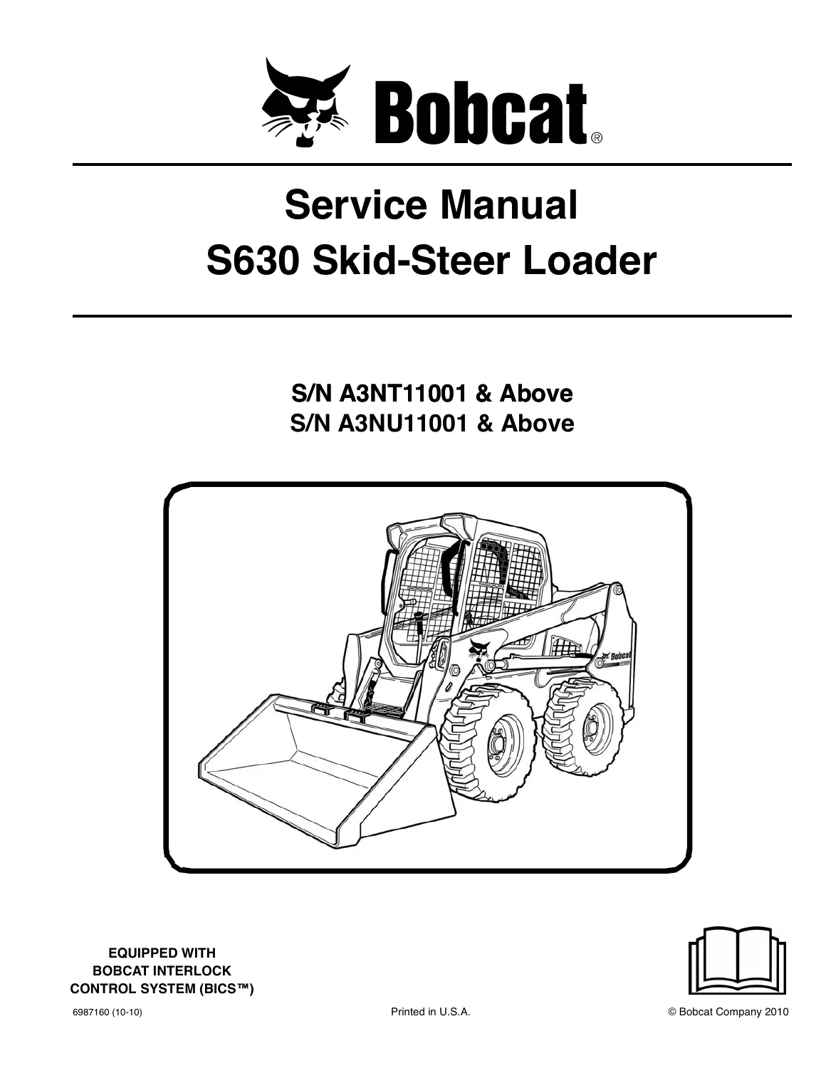
Bobcat S630 Skid-Steer Loader Service Manual 6987160 October 2010
The Bobcat S630 Skid-Steer Loader Service Manual 6987160 October 2010 is written for the loader mechanic who has to keep an S630 working after daily service, component replacement, or a full system overhaul. Publication 6987160 (10-10) applies to loaders with serial numbers A3NT11001 and above and A3NU11001 and above. Machines covered by this book are equipped with the Bobcat Interlock Control System (BICS). The opening pages locate the loader serial plate on the outside of the frame and the engine serial number on the side of the engine behind the alternator, then walk through the post-repair inspection list that must be completed before the machine goes back to a customer.
File Details
- Manual type: Service Manual
- Brand / model: Bobcat S630 Skid-Steer Loader
- Serial coverage: A3NT11001 & Above; A3NU11001 & Above
- Language: English
- Page count: 890
- File format: PDF
- Document number: 6987160 (10-10)
- Publication date: October 2010
- Copyright: Bobcat Company 2010, printed in U.S.A.
Machine Identity And Powertrain
Engine service in this S630 workshop book is built around a Kubota direct-injected V3307-DI-T turbo diesel of 3,3 L (203 in³). The specification pages list the same family as Kubota V3307-DI-TE3 Interim Tier IV: four cylinders, turbo-charged induction, closed crankcase breathing, and glow plugs that fire automatically in the RUN position. SAE 1995 gross output is given as 55,4 kW (74.3 hp) at 2400 rpm, with SAE 1995 gross torque of 264,4 N·m (195.0 lb-ft) at 1600 rpm. Low idle is 1250–1450 rpm and high idle is 2525–2650 rpm. Bore and stroke are 94 / 120 mm (3.70 / 4.72 in).
Rated operating capacity is 989 kg (2180 lb), rising to 1057 kg (2330 lb) with the 200 pound frame-mounted counterweight kit and 1080 kg (2380 lb) with the 300 pound kit. Tipping load is 1978 kg (4360 lb) and operating weight is 3496 kg (7707 lb). Travel speed is 0–11,4 km/h (0–7.1 mph) on a single-speed loader, or 0–11,4 km/h / 0–19,8 km/h (0–7.1 / 0–12.3 mph) with the two-speed option. The drive is fully hydrostatic four-wheel drive: infinitely variable tandem hydrostatic piston pumps feeding two fully reversing hydrostatic motors, then pre-stressed #120 HSOC endless roller chain in a sealed chaincase (two chains per side, no idler sprocket, no periodic chain adjustment).
Complete PDF Bookmark Tree
Complete Bookmarks
The complete bookmarks in the “Bobcat S630 Skid-Steer Loader Service Manual 6987160 October 2010” are as follows:
MAINTENANCE SAFETYp. 3
CONTENTSp. 5
+FOREWORDp. 7
FOREWORDp. 9
SAFETY INSTRUCTIONSp. 12
+FIRE PREVENTIONp. 14
Maintenancep. 14
Operationp. 14
Electricalp. 14
Hydraulic Systemp. 14
Fuelingp. 14
Startingp. 14
Spark Arrestor Exhaust Systemp. 14
Welding And Grindingp. 15
Fire Extinguishersp. 15
+SERIAL NUMBER LOCATIONSp. 16
Loader Serial Numberp. 16
Engine Serial Numberp. 16
DELIVERY REPORTp. 17
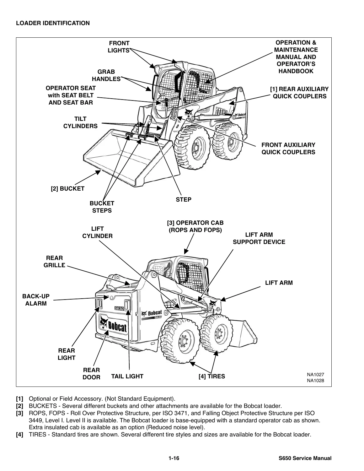
LOADER IDENTIFICATIONp. 18
+SAFETY & MAINTENANCEp. 19
+LIFTING AND BLOCKING THE LOADERp. 23
+LIFT ARM SUPPORT DEVICEp. 25
Installingp. 25
Removingp. 26
+OPERATOR CABp. 27
Descriptionp. 27
Raisingp. 28
Loweringp. 29
Cab Door Sensorp. 30
Special Applications Kitp. 30
Special Applications Kit Inspection And Maintenancep. 30
+TRANSPORTING LOADER ON A TRAILERp. 31
Loading And Unloadingp. 31
Fasteningp. 31
+TOWING THE LOADERp. 33
+REMOTE START TOOL KIT-MEL1563p. 35
Remote Start Tool – MEL1563p. 35
Service Tool Harness Control – MEL1565p. 36
Service Tool Harness Communicator – MEL1566p. 37
Remote Start Procedurep. 37
+REMOTE START TOOL (SERVICE TOOL) KIT – 7003031p. 41
Descriptionp. 41
Remote Start Tool (Service Tool) – 7003030p. 42
Loader Service Tool Harness – 6689747p. 43
Computer Service Tool Harness – 6689746p. 44
Remote Start Procedurep. 45
+SERVICE SCHEDULEp. 49
+AIR CLEANER SERVICEp. 51
Replacing Filter Elementsp. 51
+ENGINE COOLING SYSTEMp. 53
Maintenance Platformp. 53
Cleaningp. 53
Checking Levelp. 55
Removing And Replacing Coolantp. 55
+FUEL SYSTEMp. 57
Fuel Specificationsp. 57
Biodiesel Blend Fuelp. 57
Filling The Fuel Tankp. 58
Fuel Filterp. 59
Removing Air From The Fuel Systemp. 59
+ENGINE LUBRICATION SYSTEMp. 61
Checking And Adding Engine Oilp. 61
Engine Oil Chartp. 61
Removing And Replacing Oil And Filterp. 62
+HYDRAULIC / HYDROSTATIC SYSTEMp. 63
Checking And Adding Fluidp. 63
Hydraulic / Hydrostatic Fluid Chartp. 63
Removing And Replacing Hydraulic Fluidp. 64
Removing And Replacing Hydraulic / Hydrostatic Filterp. 66
Removing And Replacing Hydraulic Charge Filterp. 68
Breather Capp. 69
+FINAL DRIVE TRANSMISSION (CHAINCASE)p. 71
Checking And Adding Oilp. 71
Removing And Replacing Oilp. 71
+BOB-TACH (HAND LEVER)p. 73
Inspection And Maintenancep. 73
+BOB-TACH (POWER)p. 75
Inspection And Maintenancep. 75
+LUBRICATING THE LOADERp. 77
Lubrication Locationsp. 77
+TIRE MAINTENANCEp. 79
Wheel Nutsp. 79
Rotatingp. 79
Mountingp. 79
+SPARK ARRESTOR MUFFLERp. 81
+PIVOT PINSp. 83
Inspection And Maintenancep. 83
+LOADER STORAGE AND RETURN TO SERVICEp. 85
Storagep. 85
Return To Servicep. 85
+STOPPING THE ENGINE AND LEAVING THE LOADERp. 87
+EMERGENCY EXITp. 89
External Accessp. 89
Rear Windowp. 89
Front Doorp. 89
+SEAT BELTp. 91
Inspection And Maintenancep. 91
+HYDRAULIC SYSTEMp. 93
HYDRAULIC / HYDROSTATIC SCHEMATICS
+HYDRAULIC SYSTEM INFORMATIONp. 105
Glossary Of Hydraulic / Hydrostatic Symbolsp. 105
Troubleshootingp. 109
+CYLINDER (LIFT)p. 111
Testingp. 111
Removal And Installationp. 112
Parts Identificationp. 114
Disassemblyp. 115
Assemblyp. 117
+CYLINDER (TILT)p. 119
Testingp. 119
Removal And Installationp. 120
Base End Pivot Pin Removal And Installationp. 122
Parts Identificationp. 123
Disassemblyp. 124
Assemblyp. 126
+CYLINDER (BOB-TACH)p. 129
Testingp. 129
Removal And Installationp. 130
Parts Identificationp. 131
Disassemblyp. 132
Assemblyp. 133
+MAIN RELIEF VALVEp. 137
Descriptionp. 137
Testingp. 138
Adjustingp. 140
Removal And Installationp. 141
+HYDRAULIC CONTROL VALVE (STANDARD)p. 143
Descriptionp. 143
Removal And Installationp. 144
Mount Bracket Removal And Installationp. 147
Identification Chartp. 148
Lift Load Check Valve Removal And Installationp. 149
Load Check Valve Removal And Installation (Tilt & Auxiliary)p. 150
Anti-Cavitation Valve Removal And Installation (Lift, Rod End)p. 151
Port Relief / Anti-Cavitation Valve Removal And Installation (Lift, Base End)p. 151
Port Relief / Anti-Cavitation Valve Removal And Installation (Tilt, Base End)p. 152
Port Relief / Anti-Cavitation Valve Removal And Installation (Tilt, Rod End)p. 152
Port Relief Valve Removal And Installationp. 153
Plug Removal And Installationp. 154
Rubber Boot Removal And Installationp. 155
End Cap Block Removal And Installationp. 156
Lift Spool And Detent Removal And Installationp. 157
Tilt Spool Removal And Installationp. 167
Auxiliary Spool Removal And Installationp. 169
Auxiliary Solenoid Removal And Installationp. 171
Solenoid Removal And Installationp. 172
Lock Valve Removal And Installationp. 173
Lift Arm Bypass Orifice Removal And Installationp. 175
Main Relief Valve Removal And Installationp. 175
Check Valve Removal And Installationp. 176
+HYDRAULIC CONTROL VALVE (ACS) OR (SJC)p. 177
Descriptionp. 177
Removal And Installationp. 177
Actuator Removal And Installation (In Loader)p. 181
Actuator Removal And Installation (Out Of Loader)p. 183
Identification Chartp. 186
Mount Bracket Removal And Installationp. 187
Lift Load Check Valve Removal And Installationp. 187
Load Check Valve Removal And Installation (Tilt & Auxiliary)p. 188
Anti-Cavitation Valve Removal And Installation (Lift, Rod End)p. 189
Port Relief / Anti-Cavitation Valve Removal And Installation (Lift, Base End)p. 189
Port Relief / Anti-Cavitation Valve Removal And Installation (Tilt, Base End)p. 190
Port Relief / Anti-Cavitation Valve Removal And Installation (Tilt, Rod End)p. 190
Port Relief Valve Removal And Installationp. 191
Plug Removal And Installationp. 192
End Cap Block Removal And Installationp. 193
Lift Spool Removal And Installationp. 193
Tilt Spool Removal And Installationp. 198
Auxiliary Spool Removal And Installationp. 200
Auxiliary Solenoid Removal And Installationp. 202
Solenoid Removal And Installationp. 203
Lock Valve Removal And Installationp. 204
Lift Arm Bypass Orifice Removal And Installationp. 205
Main Relief Valve Removal And Installationp. 205
Check Valve Removal And Installationp. 206
+LIFT ARM BYPASS CONTROL VALVEp. 207
Descriptionp. 207
Testingp. 207
Removal And Installationp. 208
Bracket Removal And Installationp. 209
Disassembly And Assemblyp. 209
+HYDRAULIC PUMPp. 211
Descriptionp. 211
Pump Test At Quick Couplersp. 211
Direct Pump Test (Standard Section)p. 212
Direct Pump Test (Charge Section)p. 214
Removal And Installationp. 216
Hydraulic Pump Startupp. 217
Parts Identificationp. 218
Disassembly And Assemblyp. 219
+HYDRAULIC PUMP (HIGH FLOW)p. 221
Descriptionp. 221
Pump Test At Quick Couplersp. 221
Direct Pump Test (Standard Section)p. 222
Direct Pump Test (Charge Section)p. 223
Direct Pump Test (High Flow Section)p. 225
High Flow Relief Valve Adjustmentp. 227
High Flow Relief Valve Removal And Installationp. 228
Solenoid Removal And Installationp. 229
Removal And Installationp. 230
Hydraulic Pump Startupp. 231
Parts Identificationp. 232
Disassembly And Assemblyp. 233
+HYDRAULIC / HYDROSTATIC FILTERSp. 235
Descriptionp. 235
Housing Removal And Installationp. 235
+HYDRAULIC FLUID RESERVOIRp. 237
Descriptionp. 237
Removal And Installationp. 237
Hydraulic Fluid Screenp. 238
+OIL COOLERp. 239
Descriptionp. 239
Removal And Installationp. 239
+BUCKET POSITION VALVEp. 241
Descriptionp. 241
Solenoid Removal And Installationp. 241
Solenoid Testingp. 242
Removal And Installationp. 242
Disassembly And Assemblyp. 244
+REAR AUXILIARY DIVERTER VALVEp. 245
Descriptionp. 245
Solenoid Testingp. 245
Removal And Installationp. 246
Disassembly And Assemblyp. 247
+BOB-TACH (POWER) BLOCKp. 253
Descriptionp. 253
Removal And Installationp. 253
Disassembly And Assemblyp. 255
+FRONT AUXILIARY HYDRAULIC COUPLER BLOCKp. 259
Descriptionp. 259
Removal And Installationp. 259
Disassembly And Assemblyp. 259
+HYDROSTATIC SYSTEMp. 261
+HYDROSTATIC SYSTEM INFORMATIONp. 263
Troubleshootingp. 263
Descriptionp. 264
+HYDROSTATIC DRIVE MOTORp. 265
Descriptionp. 265
Removal And Installationp. 266
Parts Identificationp. 268
Disassembly And Assemblyp. 269
+HYDROSTATIC DRIVE MOTOR (TWO-SPEED)p. 273
Descriptionp. 273
Removal And Installationp. 273
Parts Identificationp. 276
Disassemblyp. 277
Assemblyp. 283
+HYDROSTATIC MOTOR CARRIERp. 289
Descriptionp. 289
Removal And Installationp. 290
Parts Identificationp. 291
Disassemblyp. 292
Assemblyp. 293
+HYDROSTATIC MOTOR CARRIER (SJC)p. 295
Descriptionp. 295
Removal And Installationp. 296
Parts Identificationp. 297
Disassemblyp. 298
Assemblyp. 300
+CHARGE PRESSUREp. 303
Descriptionp. 303
Testingp. 303
Sender Removal And Installationp. 305
Adjustingp. 306
+HYDROSTATIC PUMPp. 309
Descriptionp. 309
Removal And Installationp. 310
Hydrostatic Pump Startupp. 311
Replenishing / High Pressure Relief Valve Removal And Installationp. 312
Parts Identification (Left Half)p. 313
Parts Identification (Right Half)p. 314
Disassemblyp. 315
Assemblyp. 322
+HYDROSTATIC PUMP (SJC)p. 329
Descriptionp. 329
Hydraulic Controller Removal And Installationp. 330
Removal And Installationp. 332
Hydrostatic Pump Start Upp. 333
Parts Identificationp. 334
High Pressure Relief And Bypass Valvep. 335
Charge Relief Valvep. 336
Disassembly And Assemblyp. 337
Mechanical Neutral Adjustmentp. 350
Hydraulic Controller Neutral Adjustmentp. 353
+DRIVE BELTp. 357
Belt Adjustmentp. 357
Belt Replacementp. 357
Stop Adjustmentp. 359
Tensioner Pulley Removal And Installationp. 360
Tensioner Pulley Disassembly And Assemblyp. 360
+TWO-SPEED / BRAKE VALVEp. 363
Descriptionp. 363
Valve Block Removal And Installationp. 364
Valve Block Disassembly And Assemblyp. 366
+DRAIN MANIFOLDp. 369
Descriptionp. 369
Drain Manifold Removal And Installationp. 369
+DRIVE SYSTEMp. 371
+BRAKE (SINGLE SPEED)p. 373
Descriptionp. 373
Disc Removal And Installationp. 373
+BRAKE (TWO-SPEED)p. 375
+DRIVE COMPONENTSp. 377
Descriptionp. 377
Axle Seal Removal And Installationp. 378
Axle, Sprocket And Bearings Removal And Installationp. 380
Chain Removal And Installationp. 385
+CHAINCASEp. 387
Descriptionp. 387
Front Cover Removal And Installationp. 387
Center Cover Removal And Installationp. 388
Rear Cover Removal And Installationp. 389
+MAINFRAMEp. 391
+SEAT BARp. 395
Descriptionp. 395
Removal And Installationp. 395
Disassembly And Assemblyp. 396
Compression Spring Disassembly And Assemblyp. 397
+OPERATOR CABp. 399
Gas Spring Removal And Installationp. 399
Gas Spring Bracket Disassembly And Assemblyp. 400
Removal And Installationp. 400
+OPERATOR SEATp. 403
Removal And Installationp. 403
Seat Belt Removal And Installation (Retractable)p. 403
Seat Belt And Bracket Removal And Installation (Standard)p. 404
Seat Belt Bracket Removal And Installationp. 404
+OPERATOR SEAT (SUSPENSION)p. 405
Removal And Installationp. 405
Slide Rail Removal And Installationp. 405
Seat Belt Removal And Installationp. 406
Lower Cushion Removalp. 406
Lower Cushion Installationp. 407
Back Cushion Removal And Installationp. 407
Shock Removal And Installationp. 408
3-Point Seat Belt Removal And Installationp. 408
+BOB-TACH (HAND LEVER)p. 411
Descriptionp. 411
Removal And Installationp. 411
Lever And Wedge Disassembly And Assemblyp. 413
Pivot Pin Bushing And Seal Removal And Installationp. 415
+BOB-TACH (POWER)p. 417
Descriptionp. 417
Removal And Installationp. 417
Lever And Wedge Disassembly And Assemblyp. 420
Pivot Pin Bushing And Seal Removal And Installationp. 421
+LIFT ARMSp. 423
Removal And Installationp. 423
+REAR GRILLEp. 425
Removal And Installationp. 425
+REAR DOOR (TAILGATE)p. 427
Removal And Installationp. 427
Striker Removal And Installationp. 428
Striker Disassembly And Assemblyp. 428
Striker (Adjusting)p. 428
Latch Removal And Installationp. 429
+FUEL TANKp. 431
Removal And Installationp. 431
Fuel Level Sender Removal And Installationp. 433
Fuel Fill Screen Removal And Installationp. 433
+CONTROL PEDALS AND LINKAGESp. 435
Descriptionp. 435
Pedal Removal And Installationp. 435
Linkage Removal And Installationp. 436
Pedal (Adjusting)p. 437
Floor Pan Removal And Installationp. 438
+CONTROL PEDALS AND LINKAGES (ACS)p. 439
Descriptionp. 439
Pedal Removal And Installationp. 439
Linkage Removal And Installationp. 440
Pedal (Adjusting)p. 440
Floor Pan Removal And Installationp. 441
+CONTROL PANELp. 443
Descriptionp. 443
Removal And Installationp. 444
Disassembly And Assemblyp. 445
Linkage Removal And Installationp. 447
Pintle Arm Disassembly And Assemblyp. 451
Linkage Neutral (Adjusting)p. 452
Linkage Travel (Adjusting)p. 456
Shock Removal And Installationp. 460
+CONTROL PANEL (SJC)p. 461
Descriptionp. 461
Removal And Installationp. 461
+CONTROL HANDLE / LEVERp. 463
Descriptionp. 463
Lever Removal And Installationp. 463
Boot Removal And Installationp. 464
+CONTROL HANDLE / LEVER (ACS)p. 465
Descriptionp. 465
Handle Sensor Removal And Installationp. 465
Handle Removal And Installationp. 468
Handle Disassembly And Assemblyp. 469
Lever Removal And Installationp. 469
Boot Removal And Installationp. 470
+CONTROL HANDLE / LEVER (SJC)p. 471
Descriptionp. 471
Joystick Testingp. 471
Joystick Removal And Installationp. 472
+ACCESS PANEL (INSIDE)p. 473
Removal And Installation (Left)p. 473
Removal And Installation (Right)p. 473
+ACCESS PANEL (INSIDE) (SJC)p. 475
Removal And Installation (Left)p. 475
Removal And Installation (Right)p. 475
+WINDOW (REAR)p. 477
Removal And Installationp. 477
Disassembly And Assemblyp. 477
+WINDOW (TOP)p. 479
Removal And Installationp. 479
+WINDOW (SIDE)p. 481
Removal And Installationp. 481
+CAB DOORp. 483
Descriptionp. 483
Removal And Installationp. 483
Disassembly And Assemblyp. 484
Aligningp. 485
Adjustingp. 486
Checking Operationp. 486
+ARMRESTp. 487
Descriptionp. 487
Removal And Installationp. 488
Disassembly And Assemblyp. 489
+LEFT SIDE LOWER PANELp. 491
Removal And Installationp. 491
Disassembly And Assemblyp. 493
+RIGHT SIDE LOWER PANELp. 495
Removal And Installationp. 495
Disassembly And Assemblyp. 496
+HEADLINERp. 499
Removal And Installationp. 499
+ELECTRICAL SYSTEM & ANALYSISp. 501
ELECTRICAL SCHEMATICS
+ELECTRICAL SYSTEM INFORMATIONp. 533
Glossary Of Electrical Symbolsp. 533
Standard Cab Harness Connectorsp. 536
Deluxe Cab Harness Connectorsp. 537
Mainframe Harness Connectorsp. 538
Descriptionp. 539
Troubleshootingp. 540
Fuse And Relay Location / Identificationp. 541
Solenoid Testingp. 544
+BATTERYp. 545
Removal And Installationp. 545
Servicingp. 546
Using A Booster Battery (Jump Starting)p. 547
+ALTERNATORp. 549
Belt Adjustmentp. 549
Belt Replacementp. 549
Charging System Inspectionp. 550
Alternator Voltage Testingp. 551
Low Voltage Testingp. 551
High Voltage Testingp. 552
Removal And Installationp. 553
Parts Identificationp. 554
+STARTERp. 555
Testingp. 555
Removal And Installationp. 555
Parts Identificationp. 556
+INSTRUMENT PANELSp. 557
Left Panelp. 557
Display Screenp. 559
Right Panel (Standard Key Panel)p. 560
Right Panel (Keyless Start Panel)p. 561
Right Panel (Deluxe Instrumentation Panel)p. 562
Left Switch Panelp. 564
Right Switch Panelp. 564
Left Panel Removal And Installationp. 565
Right Panel (Standard Key Panel) Removal And Installationp. 565
Right Panel (Keyless Start Panel) Removal And Installationp. 566
Right Panel (Deluxe Instrumentation Panel) Removal And Installationp. 566
Key Switch Disassembly And Assemblyp. 567
Alarm Disassembly And Assemblyp. 567
Left Switch Panel Removal And Installationp. 568
Right Switch Panel Removal And Installationp. 568
+LIGHTSp. 569
Front Removal And Installationp. 569
Rear Removal And Installationp. 570
Cab Light Removal And Installationp. 570
+BOBCAT CONTROLLERS (GATEWAY AND AUXILIARY)p. 571
Descriptionp. 571
Connector Identificationp. 572
Removal And Installationp. 578
+BOBCAT CONTROLLER (ACS)p. 579
Descriptionp. 579
Connector And Wire Identificationp. 580
Removal And Installationp. 581
+BOBCAT CONTROLLER (SJC) (DRIVE)p. 583
Descriptionp. 583
Connector Identificationp. 584
Removal And Installationp. 586
+SPEED SENSORS (SJC)p. 587
Descriptionp. 587
Testingp. 587
Removal And Installationp. 589
+DIAGNOSTIC SERVICE CODESp. 591
Viewing Service Codesp. 591
Service Codes Listp. 592
+BOBCAT INTERLOCK CONTROL SYSTEM (BICS)p. 597
Descriptionp. 597
Inspecting The BICS (Engine STOPPED – Key ON)p. 598
Inspecting Deactivation Of The Auxiliary Hydraulics System (Engine STOPPED – Key ON)p. 598
Inspecting The Seat Bar Sensor (Engine RUNNING)p. 598
Inspecting The Traction Lock (Engine RUNNING)p. 598
Inspecting The Lift Arm Bypass Controlp. 598
Inspecting Deactivation Of Lift And Tilt Functions (ACS And SJC)p. 598
Troubleshootingp. 599
+SEAT BAR SENSORp. 601
Descriptionp. 601
Troubleshootingp. 601
Testingp. 602
Removal And Installationp. 603
Bobcat Interlock Control System (BICS) Circuit Testp. 604
+TRACTION LOCKp. 607
Descriptionp. 607
Troubleshootingp. 608
Inspectingp. 609
+CONTROL SYSTEM (ACS)p. 611
Descriptionp. 611
Troubleshootingp. 612
Handle Sensor Connector Disassembly And Assemblyp. 613
Switch Handle Removalp. 614
Switch Handle Installationp. 616
Actuator Connector Disassembly And Assemblyp. 619
Handle Lock Solenoid Removal And Installationp. 620
Handle Lock Solenoid Disassembly And Assemblyp. 620
Foot Sensor Removal And Installationp. 621
Foot Sensor Disassembly And Assemblyp. 622
Foot Sensor Lock Solenoid Removal And Installationp. 622
+ELECTRICAL / HYDRAULIC CONTROLSp. 623
Identification Chartp. 623
Descriptionp. 624
Identification Chart ACD Group 0p. 625
Identification Chart ACD Group 1p. 626
Identification Chart ACD Group 2p. 627
Identification Chart ACD Group 3p. 628
+ELECTRICAL / HYDRAULIC CONTROLS (ACS)p. 629
Identification Chartp. 629
Descriptionp. 630
Identification Chart ACD Group 0p. 631
Identification Chart ACD Group 1p. 632
Identification Chart ACD Group 2p. 633
Identification Chart ACD Group 3p. 634
+ELECTRICAL / HYDRAULIC CONTROLS (SJC)p. 635
Identification Chartp. 635
Descriptionp. 636
Identification Chart ACD Group 0p. 637
Identification Chart ACD Group 1p. 638
Identification Chart ACD Group 2p. 639
Identification Chart ACD Group 3p. 640
+SERVICE PC (LAPTOP COMPUTER)p. 641
Connecting Remote Start Toolp. 641
Connecting Remote Start Tool (Service Tool)p. 641
+CALIBRATIONp. 643
Descriptionp. 643
Actuator Testingp. 643
Lift And Tilt Calibration (SJC)p. 646
Hydrostatic Pump Calibration (SJC)p. 648
Lift And Tilt Calibration (ACS)p. 653
+STEERING DRIFT COMPENSATIONp. 655
Descriptionp. 655
Operationp. 655
+FLYWHEEL RPM SENSORp. 657
Descriptionp. 657
Adjustmentp. 658
+CONTROL PANEL SETUPp. 659
Right Panel Setup (Deluxe Instrumentation Panel)p. 659
+PASSWORD SETUP (DELUXE INSTRUMENTATION PANEL)p. 661
Password Descriptionp. 661
Changing The Owner Passwordp. 661
Changing The User Passwordsp. 662
Password Lockout Featurep. 662
+PASSWORD SETUP (KEYLESS START PANEL)p. 663
Password Descriptionp. 663
Changing The Owner Passwordp. 663
Password Lockout Featurep. 663
+MAINTENANCE CLOCKp. 665
Descriptionp. 665
Setupp. 666
Resetp. 669
+BACK-UP ALARM SYSTEMp. 671
Descriptionp. 671
Inspectingp. 671
Adjusting Switch Positionp. 672
Troubleshooting (Standard And ACS)p. 673
Troubleshooting (Joystick)p. 674
Alarm Removal And Installationp. 675
Switch Removal And Installationp. 675
+FRONT HORNp. 677
Removal And Installationp. 677
+ENGINE SERVICEp. 679
+ENGINE INFORMATIONp. 683
Descriptionp. 683
Specificationsp. 684
Torque Valuesp. 687
Troubleshootingp. 687
Engine Removal And Installationp. 689
Engine Mount Replacementp. 696
Compression – Checkingp. 697
+ENGINE SPEED CONTROLp. 699
Removal And Installationp. 699
Disassembly And Assemblyp. 699
Cable Removal And Installationp. 700
+ENGINE SPEED CONTROL (SJC) S/N A3NU11889 AND BELOW & S/N A3NU11024 AND BELOWp. 701
Removal And Installationp. 701
Disassembly And Assemblyp. 702
+ENGINE SPEED CONTROL (SJC) S/N A3NT11900 AND ABOVE & S/N A3NU11025 AND ABOVEp. 705
Removal And Installationp. 705
Disassembly And Assemblyp. 706
+MUFFLERp. 709
Removal And Installationp. 709
+AIR CLEANERp. 711
Housing Removal And Installationp. 711
Housing Bracket Removal And Installationp. 712
+ENGINE COOLING SYSTEMp. 713
Radiator Removal And Installationp. 713
Hydraulic Fan Descriptionp. 715
Hydraulic Fan Disassembly And Assemblyp. 716
Lower Fan Duct Removal And Installationp. 717
Blower Housing Removal And Installationp. 717
Hydraulic Fan Motor Assembly Removal And Installationp. 718
Fan Removal And Installationp. 718
Hydraulic Fan Motor Removal And Installationp. 719
Water Pump Removal And Installationp. 720
Water Pump Disassembly And Assemblyp. 720
Thermostat Housing Removal And Installationp. 721
Thermostat – Checkingp. 722
+LUBRICATION SYSTEMp. 723
Oil Pan Removal And Installationp. 723
Oil Pump Removal And Installationp. 723
Relief Valve – Testingp. 724
Oil Pump Inspectionp. 724
Oil Filter Cooler Removal And Installationp. 725
Engine Oil Pressure – Testingp. 726
+FUEL SYSTEMp. 727
Fuel Shutoff Solenoid – Checkingp. 727
Fuel Shutoff Solenoid Removal And Installationp. 727
Fuel Injection Pump – Checkingp. 728
Fuel Injection Pump Assembly, Removal And Installationp. 729
Governor Housing Disassembly And Assemblyp. 732
Governor Disassembly And Assemblyp. 734
Fuel Camshaft Removal And Installationp. 736
Fuel Injection Pump Removal And Installationp. 738
Fuel Injection Pump – Timingp. 740
Fuel Injector Removal And Installationp. 741
Fuel Injector Nozzle Pressure – Checkingp. 743
Nozzle Spray Conditionp. 744
Valve Seat Tightnessp. 744
+CYLINDER HEADp. 745
Glow Plugs – Testingp. 745
Glow Plugs Removal And Installationp. 745
Valve Clearance Adjustmentp. 746
Valve Timing – Checkingp. 747
Cylinder Head Removal And Installationp. 748
Cylinder Head Disassembly And Assemblyp. 751
Cylinder Head – Servicingp. 751
Cylinder Head Top Clearancep. 752
Valve Guide – Checkingp. 752
Valve Guide Removal And Installationp. 753
Reconditioning The Valve And Valve Seatp. 753
Valve Springp. 755
Valve Tappetsp. 756
Rocker Arm And Shaft – Checkingp. 757
Bridge Arm And Bridge Arm Shaft – Checkingp. 757
Bridge Arm Shaft – Removal And Installationp. 758
Push Rod Alignment – Checkingp. 759
+CRANKSHAFT AND PISTONSp. 761
Piston And Connecting Rod Removal And Installationp. 761
Piston And Connecting Rod – Servicingp. 762
Cylinder Bore – Checkingp. 765
Connecting Rod Alignmentp. 766
Crankshaft Gear Removal And Installationp. 766
Crankshaft And Bearings Removal And Installationp. 767
Crankshaft And Bearings – Servicingp. 769
+CAMSHAFT AND TIMING GEARSp. 773
Timing Gearcase Cover Removalp. 773
Timing Gearcase Cover Installationp. 774
Timing Gears Backlash – Checkingp. 777
Idler Gear And Camshaft Removal And Installationp. 777
Camshaft – Servicingp. 778
Idler Gear And Shaft – Servicingp. 779
+TURBOCHARGERp. 781
Descriptionp. 781
Testingp. 781
Removal And Installationp. 782
+FLYWHEEL AND HOUSINGp. 785
Flywheel Removal And Installationp. 785
Ring Gear Removal And Installationp. 787
Housing Removal And Installationp. 787
+EXHAUST GAS RECIRCULATION (EGR) SYSTEMp. 789
Descriptionp. 789
Testingp. 790
Removal And Installationp. 793
Disassembly And Assemblyp. 794
+HEATING, VENTILATION, AIR CONDITIONINGp. 795
+AIR CONDITIONING SYSTEM FLOWp. 798
Descriptionp. 798
Chartp. 799
Componentsp. 800
Safety Equipmentp. 803
+REGULAR MAINTENANCEp. 805
Filtersp. 805
Compressor Drive Belt Adjustmentp. 806
Compressor Drive Belt Replacementp. 806
Condenserp. 806
Air Conditioning Lubricationp. 806
Air Conditioning Service Chartp. 807
Evaporator / Heater Coilp. 808
+TROUBLESHOOTINGp. 809
Blower Motor Does Not Operatep. 809
Blower Motor Operates Normally, But Air Flow Is Insufficientp. 809
Insufficient Cooling Although Air Flow And Compressor Operation Are Normalp. 809
The Compressor Does Not Operate At All, Or Operates Improperlyp. 809
Gauge Pressure Related Troubleshootingp. 810
Troubleshooting Treep. 812
Temperature / Pressure Chartp. 816
Poor A/C Performancep. 818
HVAC Repair And Leaksp. 819
Electrical Systemp. 820
Engine Coolant Bypassing The Heater Valvep. 826
Heater Valve Not Opening Or Closingp. 827
+SYSTEM CHARGING AND RECLAMATIONp. 829
Refrigerant Identificationp. 829
Reclamation And Charging With Recovery / Charging Unitp. 830
+COMPRESSORp. 833
Removal And Installationp. 833
Oilp. 834
Oil Checkp. 835
+CONDENSERp. 837
Removal And Installationp. 837
+RECEIVER / DRIERp. 839
Receiver / Drier Removal And Installationp. 839
Pressure Relief Valve Removal And Installationp. 840
Pressure Switch Removal And Installationp. 841
Schraeder Valve Removal And Installationp. 842
+EVAPORATOR / HEATER UNITp. 843
Removal And Installationp. 843
+THERMOSTATp. 845
Descriptionp. 845
Removal And Installationp. 846
+EXPANSION VALVEp. 847
Removal And Installationp. 847
+EVAPORATOR COILp. 849
Removal And Installationp. 849
+HEATER COILp. 851
Removal And Installationp. 851
+BLOWER FANp. 853
Removal And Installationp. 853
Disassembly And Assemblyp. 853
+HEATER VALVEp. 857
Removal And Installationp. 857
+SPECIFICATIONSp. 859
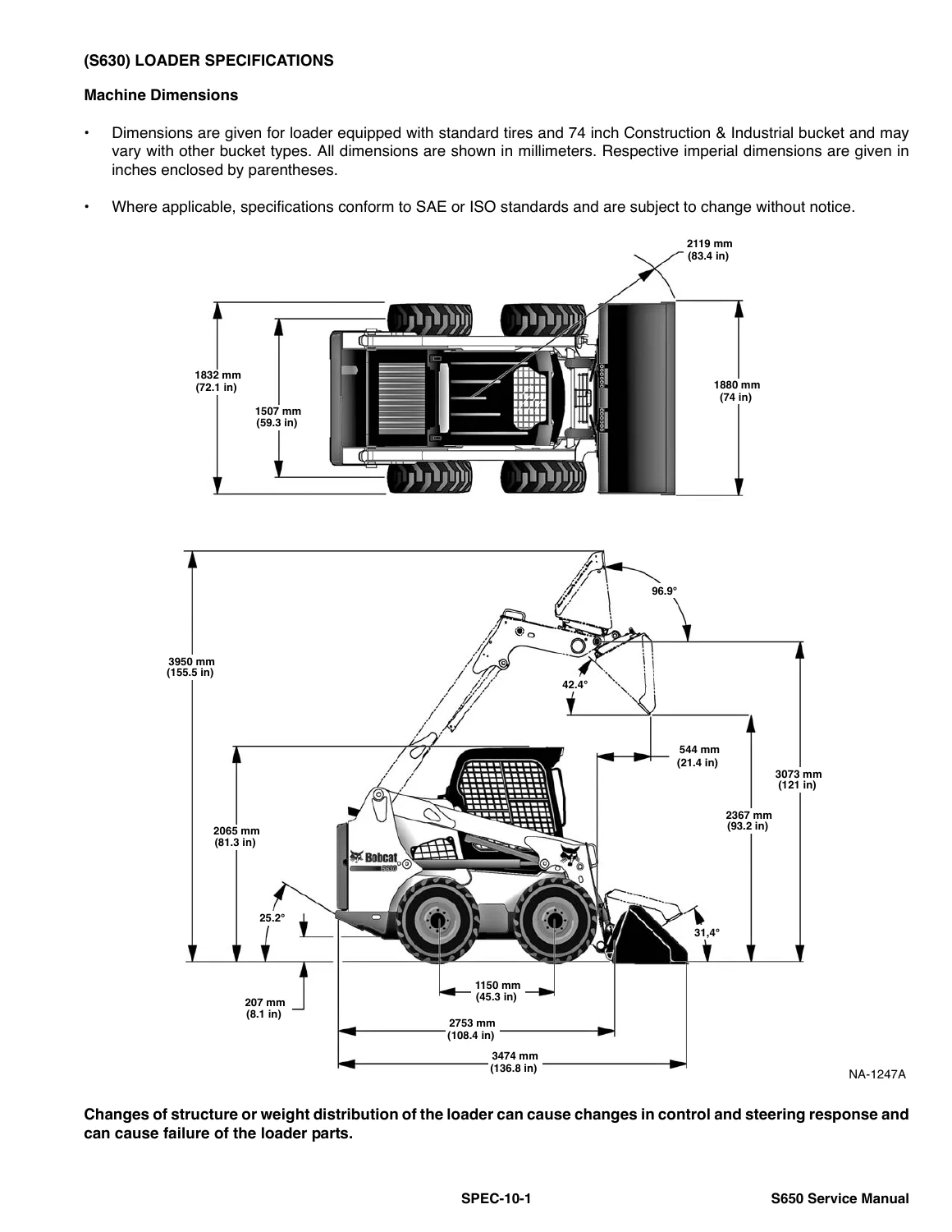
+(S630) LOADER SPECIFICATIONSp. 861
Machine Dimensionsp. 861
Performancep. 862
Enginep. 862
Drive Systemp. 862
Controlsp. 863
Hydraulic Systemp. 863
Electrical Systemp. 864
Capacitiesp. 864
Tiresp. 864
+TORQUE SPECIFICATIONS FOR BOLTSp. 865
Torque For General SAE Boltsp. 865
Torque For General Metric Boltsp. 866
+HYDRAULIC CONNECTION SPECIFICATIONSp. 867
Straight Thread O-ring Fittingp. 867
Flare Fittingp. 868
Tubelines And Hosesp. 868
+HYDRAULIC / HYDROSTATIC FLUID SPECIFICATIONSp. 869
+CONVERSIONSp. 871
Decimal And Millimeter Equivalent Chartp. 871
U.S. To Metric Conversion Chartp. 871
ALPHABETICAL INDEXp. 873
+SERVICE MANUAL REVISIONp. 877
Revision No: S630 – 1p. 877
Revision No: S630 – 2p. 879
Revision No: S630 – 3p. 881
Revision No: S630 – 4p. 883
Revision No: S630 – 5p. 885
Revision No: S630 – 6p. 887
Revision No: S630 – 7p. 889
Chapters Covered
- Safety & Maintenance — lifting and blocking the loader; lift arm support device; operator cab raise/lower and cab door sensor; trailer transport and towing; Remote Start Tool Kit MEL1563 and Service Tool Kit 7003031; service schedule; air cleaner; engine cooling; fuel system and biodiesel notes; engine lubrication; hydraulic/hydrostatic fluid, filters, and breather; chaincase oil; hand-lever and power Bob-Tach inspection; lubrication points; tires; spark arrestor muffler; pivot pins; storage and return to service; emergency exit; seat belt
- Hydraulic System — symbol glossary and troubleshooting; lift, tilt, and Bob-Tach cylinders (test, R&I, parts ID, disassembly/assembly); main relief valve test and adjustment; hydraulic pump and high-flow pump tests; control valve work for standard, ACS, and SJC machines
- Hydrostatic System — hydrostatic pump and motor service, charge circuit, drive belt and tensioner, controller bleed and calibration after pump or controller replacement
- Drive System — single-speed and two-speed brakes; axle seals, axles, sprockets, and bearings; chain R&I; chaincase covers
- Mainframe — seat bar; operator cab gas springs and cab R&I; standard and suspension seats; hand-lever and power Bob-Tach; lift arms; rear grille
- Electrical System & Analysis — harness connectors, fuse and relay ID, solenoid testing; battery service and jump starting; alternator belt, voltage, and charging tests; starter; standard key, keyless, and Deluxe Instrumentation panels; diagnostic service codes; BICS inspection; traction lock; ACS/SJC calibration; flywheel RPM sensor; password lockout; back-up alarm
- Engine Service — engine description, specifications, torque values, and troubleshooting; engine and hydrostatic pump package R&I; mounts; compression test; speed control (standard and SJC serial breaks); muffler; air cleaner housing; radiator, hydraulic fan, water pump, thermostat; lubrication system and oil pressure test; fuel shutoff, injection pump, governor, and injectors; cylinder head, valves, pistons, crankcase; timing gearcase and camshaft; turbocharger; flywheel and housing; EGR system tests and R&I
- Heating, Ventilation, Air Conditioning — heater valve, compressor belt and oil, system charging, diagnostics
- Specifications — S630 machine dimensions and performance; engine and drive data; controls; hydraulic flow and relief; electrical and capacities; tire options; SAE/metric bolt torque; hydraulic connection specs; hydraulic/hydrostatic fluid viscosity; conversion charts
- Alphabetical Index
Taken together, those sections give a technician a single path from daily fluid checks through cylinder rebuilds, hydrostatic calibration, chaincase work, BICS verification, and in-frame or out-of-frame Kubota engine repair. The book is not an operator handbook; the foreword sends the owner to the Operation & Maintenance Manual for starting and daily checks, and keeps this volume focused on shop procedures, adjustments, and analysis.
Hydraulic And Hydrostatic Work You Can Perform
Hydraulic pages start with a troubleshooting chart for no action, slow action, rough action, lift arms that creep in neutral, and lift that is slow at full engine RPM. Lift, tilt, and Bob-Tach cylinders are tested for internal leakage, then removed, torn down, and assembled with parts identification drawings. The main relief valve is described as the pressure limiter that dumps oil back to the reservoir; the book shows how to connect a hydraulic tester, warm oil to 60°C (140°F), read relief at high idle, and adjust. System relief at the quick couplers is specified as 23,8–24,5 MPa (237,8–244,7 bar) (3450–3550 PSI). Standard gear-pump capacity is 87,1 L/min (23.0 U.S. gpm); the high-flow option is 115,5 L/min (30.5 U.S. gpm). High-flow relief is checked against 24,1 MPa (3500 psi) and 25,5 MPa (3700 psi) targets with a 1/4-turn adjuster. Filters are beta 10 micron = 200 drop-in elements for both the hydraulic/hydrostatic circuit and the charge circuit.
Cylinder geometry is listed so a rebuild can be checked against printed numbers: lift bore 63,5 mm (2.50 in), tilt bore 76,2 mm (3.00 in), lift rod 44,5 mm (1.75 in), tilt rod 41,4 mm (1.63 in), lift stroke 860,3 mm (33.87 in), tilt stroke 354,8 mm (13.97 in). Function times are 3.4 s raise, 3.0 s lower, 2.3 s dump, and 1.7 s rollback. Hydrostatic service includes case-drain bleed, charge-pressure relief on the engine side of the pump, drive-belt stop adjustment, and a reminder that a replaced hydraulic controller requires hydrostatic pump calibration.
Electrical Analysis, BICS, And Instrumentation
The electrical section maps standard cab, deluxe cab, and mainframe harness connectors, then lists fuse and relay locations including a 100 ampere master fuse under the air cleaner. Charging-system tests compare B+ voltage against a 13.5 V threshold at idle and high idle. Starter tests separate a motor that spins from a drive that will not turn the engine. Instrument-panel coverage splits the left display (hours, RPM, speed management, maintenance clock, battery voltage, service codes, preheat, steering drift, drive response) from the right-side standard key panel, keyless start panel, and Deluxe Instrumentation Panel with password lockout and vitals screens.
Diagnostic service codes include engine oil pressure (M0409, M0414, M0415), battery voltage (M0322), air filter (M0117), and hydraulic solenoid faults. BICS inspection is written as a sequence with the engine stopped and with the engine running: seat bar, PRESS TO OPERATE LOADER, traction lock, and auxiliary hydraulics deactivation. ACS and SJC calibration procedures require jackstands, warm oil near 22°C (72°F), and a clear code list before the automatic test runs. Flywheel RPM sensor installation uses the plastic tip as a gauge against the ring gear.
Engine, Cooling, Fuel, And Capacities
Engine R&I is performed as an engine/hydrostatic pump package using removal attachment MEL1653-5. Mounting bolts tighten to 135 N·m (100 ft-lb). Compression checking uses MEL10630 plus adapter MEL1655 with the fuel stop solenoid disconnected. Valve clearance, valve timing, cylinder-head torque (187–196 N·m / 138–144 ft-lb), piston-pin and cylinder-bore limits (factory bore 94–94,022 mm, allowable 94,15 mm), connecting-rod torque (69–73 N·m / 51–54 ft-lb), and injection-nozzle opening pressure are all printed in the engine chapters. EGR service adds cold and hot coolant-temperature tests plus cooler and valve R&I with gasket orientation marked “F” downward.
Capacities the mechanic will use on the bench: fuel 103,1 L (27.2 U.S. gal); engine oil with filter 11,4 L (12.0 qt.); cooling system 11,4 L (3.0 U.S. gal) with heater or 11,7 L (3.1 U.S. gal) without; hydraulic/hydrostatic reservoir 10,2 L (2.7 U.S. gal); full hydraulic/hydrostatic system 41,6 L (11.0 U.S. gal); chaincase 39,2 L (10.35 U.S. gal). Electrical hardware is a 90 amp open-frame alternator, a 12 V battery rated 950 CCA at -18°C (0°F), and a 3,0 kW (4.02 hp) gear-reduction starter. Fuel guidance is Grade No. 2 or Grade No. 1 diesel; B5 must meet ASTM D975 or EN590. Coolant is a propylene glycol/water mix. Cab hardware after lowering is torqued to 54–61 N·m (40–45 ft-lb).
Maintenance Schedule And Shop Safety Built Into The Book
The service-schedule chart groups engine oil, air system, cooling, battery, fuel filter, and drive belts across 8–10, 50, 100, 250, 500, and 1000 hour columns. Safety pages require an approved lift arm support before any work under raised arms, jackstands under front axle tubes and rear frame corners before running the engine, and an engine-off rule before raising or lowering the ROPS/FOPS cab. Fire-prevention text covers debris in the engine bay, hydraulic leak checks without bare skin, no ether on glow-plug engines, and battery isolation before welding. Remote start tools MEL1563 / 7003030 let a technician run the machine with the cab up while traction lock and pressure-release switches stay under control.
Use The Bobcat S630 Skid-Steer Loader Service Manual 6987160 October 2010 On The Job
With this S630 service manual a shop can test and rebuild lift and tilt cylinders, set main and high-flow relief, replace hydraulic and charge filters, calibrate hydrostatic controllers, service chaincase axles and #120 chains, inspect and repair BICS and traction lock, read service codes, overhaul the Kubota V3307 diesel including injection equipment and EGR, and return the loader only after the 27-point post-service checklist and a working BICS test. Printed pressures, torque values, fluid grades, and serial breaks (including SJC speed-control splits at A3NT11900 / A3NU11025) keep those jobs on the numbers in publication 6987160 instead of guesswork.
Correct procedures and specifications matter on a hydrostatic skid-steer because a missed relief setting, a dry chaincase, or an uncalibrated controller shows up as heat, drift, or a machine that will not unlock traction. Instant PDF delivery after payment means the Bobcat S630 Skid-Steer Loader Service Manual 6987160 October 2010 is available on any device in the shop or in the field and can be printed for the bench with no shipping wait.


Reviews
There are no reviews yet.