Description
Official 2006 Ducati PaulSmart 1000 Workshop Manual – Italian & English
This is the complete factory workshop manual for the 2006 Ducati PaulSmart 1000. Produced by Ducati Motor Holding, this is the same reference used by authorized service centers for every maintenance, repair, and diagnostic procedure on the PaulSmart 1000. The manual is presented in both Italian and English, with side-by-side sections, making it ideal for professional workshops and owners worldwide.
File Details
- Manual Type: Official Ducati Factory Workshop Manual (Dealer-Level)
- Applicable Model: 2006 Ducati PaulSmart 1000
- Language: Italian & English (dual-language, parallel sections)
- Page Count: 500+ pages
- File Format: PDF
- Edition/Version: M.Y. 2006 – edizione/edition 00
Chapters Covered
The manual is organized into lettered sections covering every aspect of the motorcycle:
- Description: General information, manual structure, symbols, hazardous products, safety rules, maintenance indications
- Model-Specific Information: Identification data for the PaulSmart 1000 i.e.
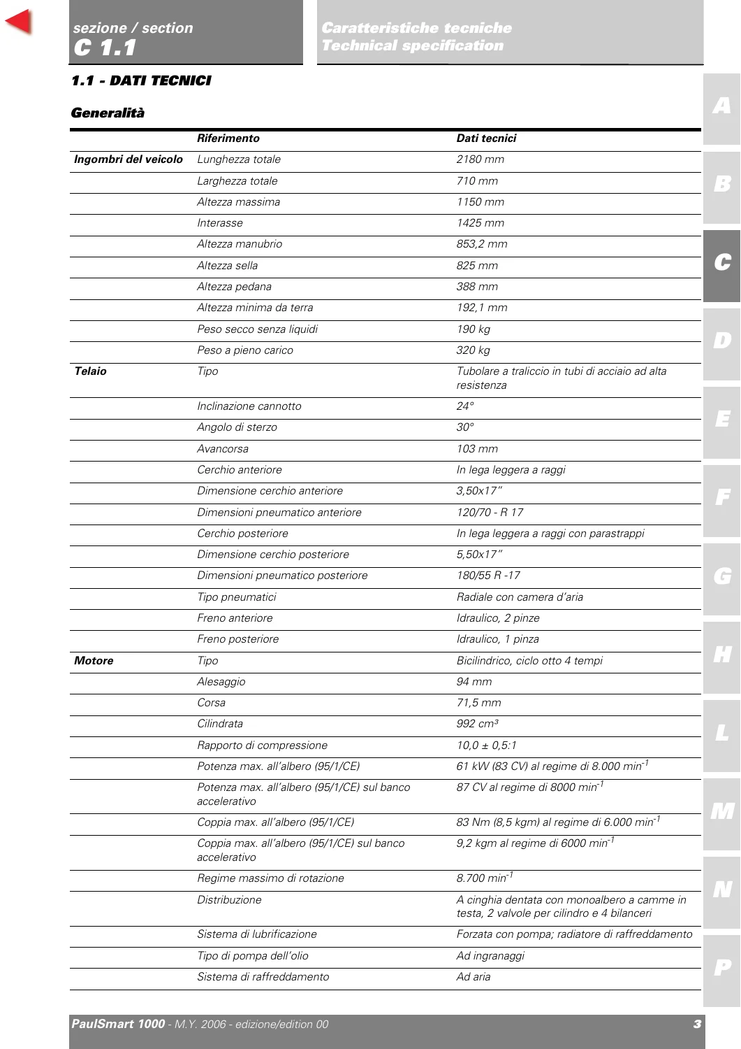
- Specifications: Complete technical data – dimensions, colors, transmission, timing system/valves, lubrication, cylinder/piston, gearbox, cooling, wheels, suspension, hydraulic brakes, charging system/injection, fuel system, lights/instrument panel, torque settings, service tools
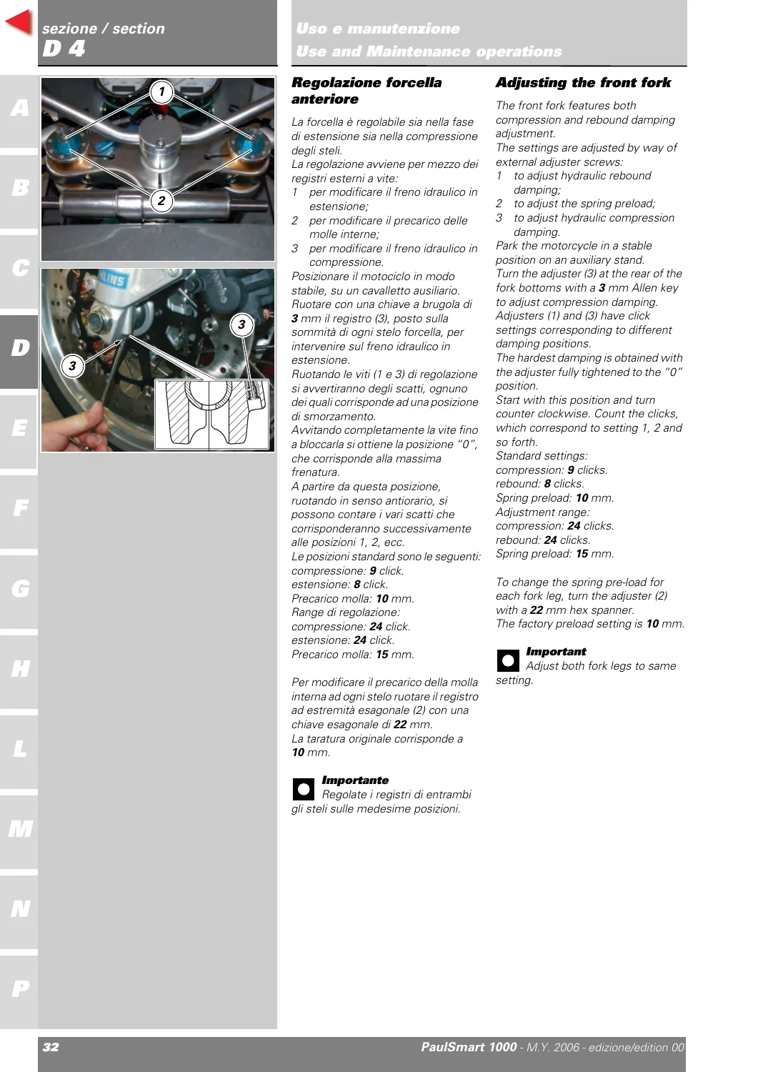
- Use and Maintenance Operation: Running-in precautions, pre-ride checks, starting/warmup, routine maintenance schedule – oil level/change, valve clearance check/adjustment, air filters, brake/clutch fluid change & bleeding, steering head bearings, chain tension, brake pad wear, throttle cable adjustment, gear/foot pedal adjustment, shock absorber and fork adjustment
- Fairing: Headlight shell, mirrors, windshield, side fairing panels, seat, front/rear mudguards, splashguard, electrical components compartment
- Controls – Devices: Throttle twistgrip, clutch hydraulic control, front brake control, rear brake control, gearchange control, seat release mechanism
- Wheels – Suspension – Brakes: Front and rear wheel overhaul, front forks, hydraulic front and rear brakes, swingarm, rear suspension, final drive (sprockets, chain washing/lubrication)
- Frame: Handlebars, steering (head bearing adjustment and disassembly), steering damper, footrest brackets, sidestand, frame checking and structural component disassembly/reassembly, tail light and number plate holder
- Fuel System – Exhaust System: Fuel tank removal and flange/cap replacement, throttle body removal/refitting, air intake and air filter box, exhaust system with catalytic converter principle, canister filter (US models)
- Ignition – Injection System: System description (fuel/air circuits, operating stages), component details – electronic control unit, injector, stepper motor, lambda sensor, air temp/pressure sensor, spark plug, coil, throttle position sensor, rpm/timing sensor, injection relay
- Engine: Complete engine removal/refitting, lubrication system (oil pump and oil cooler overhaul), heads (valve clearance and timing checks, camshafts, valves and rocker arms disassembly/reassembly), cylinders/pistons, clutch assembly (clutch unit, cover, primary drive gears), gearbox (selectors and shafts), flywheel/generator, crankcase external components, crankcase split and overhaul, connecting rods
- Electrical System: Full wiring diagram, charging system/battery, electric starting system, lights, signalling devices, safety/protection devices, instrumentation, immobilizer and transponder programming/override, diagnostic instruments and multimeter use
- Diagnostic Instruments: Detailed operation of the Ducati Diagnostic System (DDS) – power supply, DDS tester functions, timing belt tension check/adjustment, TPS reset, cylinder synchronisation, oil pressure check, cylinder compression test, fuel pressure test, immobilizer override, guided diagnosis, battery charging system test
Complete PDF Bookmark Tree
Complete Bookmarks
The complete bookmarks in the “2006 Ducati PaulSmart 1000 Factory Workshop Service Repair Manual – Italian & English” are as follows:
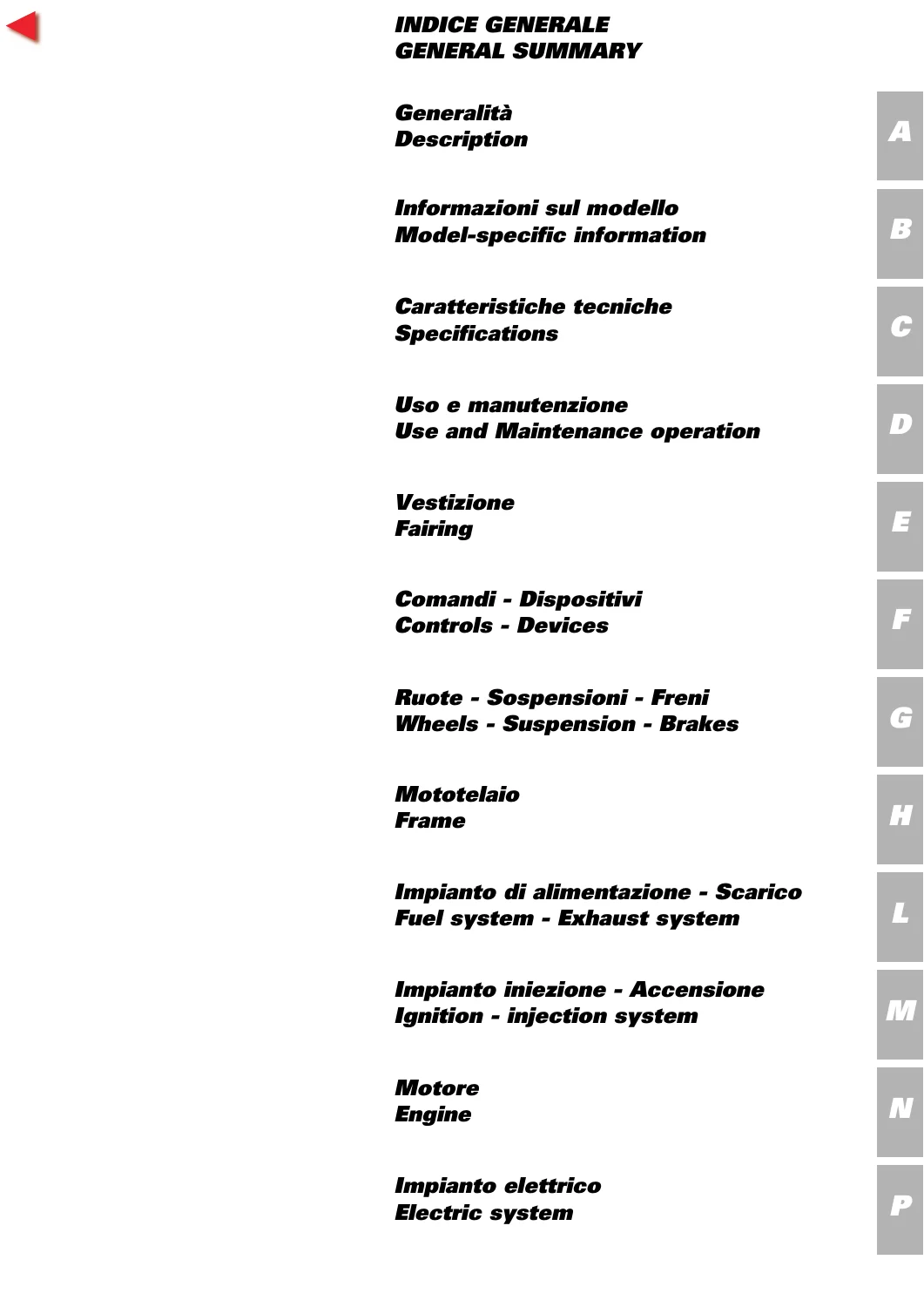
GENERAL SUMMARYp. 1
+A – Descriptionp. 11
+1 – How to use this manualp. 13
Layout of the manualp. 14
+2 – Symbols – Abbreviations – Referencesp. 15
Product specificationsp. 18
+3 – Hazardous Products – Warningsp. 20
General safety rulesp. 20
General maintenance indicationsp. 22
+B – Model-specific informationp. 25
+1 – Identification datap. 27
Identification data for the PaulSmart 1000 i.e.p. 27
+C – Technical specificationp. 29
+1.1 – Technical datap. 38
Generalp. 38
Coloursp. 39
Transmissionp. 39
Timing system/valvesp. 39
Lubrication systemp. 40
Cylinder/Pistonp. 40
Gearboxp. 41
Cooling systemp. 41
Front wheelp. 41
Front suspensionp. 41
Rear wheelp. 42
Rear suspensionp. 42
Hydraulic brakesp. 42
Charging system / alternatorp. 43
Injection systemp. 43
Fuel systemp. 43
Lights / instrument panelp. 43
1.2 – DImensionsp. 45
2 – Fuel, lubricants and other fluidsp. 46
+3 – Torque settingsp. 54
Frame torque settingsp. 54
Engine torque settingsp. 58
+4 – Service toolsp. 61
Special tools for the enginep. 61
Special tools for the framep. 65
+D – Use and Maintenance operationsp. 67
+1 – Preliminary checksp. 69
Running-in precautionsp. 69
Pre-ride checksp. 70
+2 – Starting – Engine Warmupp. 72
3 – Routine maintenance tablep. 74
+4 – Maintenance operationsp. 75
Checking the engine oil levelp. 75
Changing the engine oil and filter cartridgep. 76
Checking valve clearancesp. 77
Adjusting the valve clearancesp. 78
Changing and cleaning the air filtersp. 79
Changing the brake fluidp. 80
Draining the brake circuitp. 82
Filling the brake circuitsp. 83
Changing the clutch fluidp. 85
Draining the clutch hydraulic circuitp. 86
Filling the clutch circuitp. 87
Adjusting the steering head bearingsp. 89
Adjusting the clutch lever and front brake leverp. 90
Adjusting the chain tensionp. 91
Checking brake pad wear and changing brake padsp. 92
Adjusting the throttle cablesp. 94
Adjusting the position of the gearchange and rear brake pedalsp. 95
Adjusting the rear shock absorberp. 96
Adjusting the front forkp. 98
+5 – Diagnostic instrumentsp. 99
Description of the Ducati Diagnostic System instrumentp. 100
Tester power supplyp. 101
DDS testerp. 103
Checking and adjusting timing belt tensionp. 104
Resetting the throttle position sensor (TPS)p. 107
Cylinder synchronisationp. 110
Checking the engine oil pressurep. 111
Cylinder compression testp. 114
Fuel pressure testp. 116
Immobilizer override procedurep. 118
Guided diagnosisp. 121
Testing the battery charging systemp. 123
Icons tablep. 126
+E – Fairingp. 129
+1 – Headlight shell – Rear-view mirrorsp. 131
Removing the rear-view mirrorsp. 132
Refitting the rear-view mirrorsp. 132
Removing the rear-view mirror support armp. 132
Refitting the rear-view mirror support armp. 132
Removing the windshieldp. 133
Refitting the windshieldp. 133
Removing the headlight shell and side fairing panelsp. 134
Refitting the headlight shell and side fairing panelsp. 134
+3 – Seatp. 135
Removing the seatp. 136
Refitting the seatp. 136
Removal of the splashguard – electrical components compartmentp. 137
Refitting the splashguard – electrical components compartmentp. 137
+4 – Front and rear mudguardsp. 138
Removing the front mudguardp. 139
Disassembly of the front mudguardp. 139
Reassembly of the front mudguardp. 139
Refitting the front mudguardp. 139
Removing the rear mudguardp. 140
Refitting the rear mudguardp. 140
+F – Controls – Devicesp. 141
+1 – Throttle twistgripp. 143
Adjusting the throttle cablep. 144
Disassembly of the throttle controlp. 144
Refitting the throttle twistgripp. 144
+2 – Clutch hydraulic controlp. 146
Removing the clutch master cylinder assemblyp. 147
Refitting the clutch master cylinder assemblyp. 147
Removing the clutch slave cylinderp. 148
Refitting the clutch slave cylinderp. 149
+3 – Front brake controlp. 152
Removing the front brake master cylinderp. 153
Refitting the front brake master cylinderp. 153
+4 – Rear brake controlp. 156
Removing the rear brake master cylinderp. 157
Disassembly of the rear brake master cylinderp. 158
Refitting the rear brake master cylinderp. 158
+5 – Gearchange controlp. 160
Removal of the gearchange controlp. 161
Disassembly of the gearchange controlp. 161
Refitting the gearchange controlp. 161
+6 – Seat release mechanismp. 162
Removing the seat release mechanismp. 163
Refitting the seat release mechanismp. 163
+G – Wheels – Suspensions – Brakesp. 165
+1 – Front wheelp. 167
Removal of the front wheelp. 168
Overhauling the front wheelp. 169
Refitting the front wheelp. 173
+2 – Front forksp. 174
Removing the front forksp. 175
Overhauling the front forksp. 175
Refitting the front forksp. 176
+3 – Hydraulic front brakep. 177
Maintenance operationsp. 178
Removing the front brake systemp. 178
Overhauling the front brake componentsp. 179
Refitting the front brake systemp. 180
+4 – Rear wheelp. 182
Removing the rear wheelp. 183
Overhauling the rear wheelp. 184
Refitting the rear wheelp. 185
+5 – Swingarmp. 186
Removing the swingarmp. 187
Inspecting the swingarm pivot shaftp. 188
Checking swingarm endfloatp. 188
Refitting the swingarmp. 189
+6 – Rear hydraulic brakep. 190
Removing the rear brake systemp. 191
Overhauling the rear brake componentsp. 192
Refitting the rear brake systemp. 193
+7 – Rear suspensionp. 194
Rear suspension systemp. 195
Removing the rear shock absorberp. 195
Overhauling the rear shock absorberp. 195
Refitting the rear shock absorberp. 195
+8 – Final drivep. 196
Inspecting the final drivep. 197
Renewal of the front sprocketp. 198
Renewal of the rear sprocketp. 199
Washing the chainp. 200
Lubricating the chainp. 200
+H – Framep. 201
+1 – Handlebarsp. 203
Removing the handlebarsp. 204
Refitting the handlebarsp. 205
+2 – Steeringp. 206
Adjusting the steering head bearingsp. 207
Steering angle adjustmentp. 207
Removing the steering head componentsp. 208
Refitting the steering head componentsp. 209
+3 – Steering damperp. 211
Removing the steering damperp. 212
Refitting the steering damperp. 212
+4 – Footrest bracketsp. 213
Removing the footrestsp. 214
Refitting the footrestsp. 215
+5 – Standsp. 216
Removing the sidestand.p. 217
Disassembly of the sidestandp. 217
Inspecting the sidestandp. 217
Reassembly of the sidestandp. 217
Refitting the sidestandp. 217
+6 – Checking the framep. 218
Disassembly of structural components and the framep. 219
Checking the framep. 220
Reassembly of structural components and the framep. 224
+7 – Tail light and number plate holderp. 225
Removal of the tail light unit and the number plate holderp. 226
Refitting the tail light unit and the number plate holderp. 226
+L – Fuel system / Exhaust systemp. 227
1 – Description of fuel systemp. 229
+2 – Fuel tankp. 231
Removing the fuel tankp. 232
Replacing the tank flangep. 233
Replacing the tank cap unitp. 234
Refitting the fuel tankp. 235
+6 – Throttle bodyp. 238
Removing the throttle bodyp. 239
Refitting the throttle bodyp. 241
+7 – Air intakep. 243
Removing the air filter boxp. 244
Removing the oil breather valvep. 246
Refitting the oil breather valvep. 246
Refitting the air filter boxp. 247
+8 – Exhaust systemp. 250
Catalytic converter operating principle (EU only)p. 251
Removing the exhaust systemp. 253
Reassembling the exhaust systemp. 254
+10 – Canister filterp. 255
Canister filter system (US versions only)p. 256
Removing the canister filterp. 257
Refitting the canister filterp. 257
+M – Ignition – injection systemp. 261
+1 – Description of the fuel injection- ignition systemp. 263
General information on the fuel injection-ignition systemp. 263
Fuel circuitp. 267
Air circuitp. 268
Operating stagesp. 269
2 – Injection-ignition systemp. 270
+3 – System componentsp. 271
Electronic control unitp. 271
Electric injectorp. 274
Stepper motorp. 275
Lambda sensorp. 276
Air temperature/pressure sensorp. 278
Spark plugp. 279
Coilp. 280
Throttle position sensorp. 283
Rpm/timing sensorp. 283
Injection relayp. 284
+N – Enginep. 285
+1 – Removing – Reassembling the complete enginep. 288
Removing the enginep. 290
Refitting the enginep. 292
+2.1 – Lubrication system: Oil pumpp. 293
Lubrication systemp. 294
Disassembly of the oil pumpp. 297
Oil pump overhaulp. 298
Reassembly of the oil pumpp. 298
Refitting the oil pumpp. 299
+2.2 – Lubrication system: Oil coolerp. 300
Removing the oil coolerp. 301
Oil cooler inspectionp. 301
Refitting the oil coolerp. 302
+4.1 – Heads assy.: Checks and adjustmentsp. 303
Checking and adjusting valve clearancep. 304
Checking the engine timingp. 308
+4.2 – Head assy.: Side covers / Timing systemp. 310
Removing the lateral timing coversp. 311
Disassembly of timing assy.p. 312
Disassembly of the mobile tensionerp. 314
Disassembly of the rollersp. 314
Reassembling the timing unitp. 315
Refitting the lateral timing coversp. 320
+4.3 – Heads assy.: Camshaftsp. 321
Disassembling the engine oil temperature sensorp. 322
Refitting the engine oil temperature sensorp. 322
Removing the intake manifoldsp. 323
Refitting the intake manifoldsp. 323
Removing side coversp. 324
Removing the valve coversp. 325
Refitting the valve coversp. 325
Removing the camshaftsp. 326
Checking camshaftsp. 327
Checking oil sealsp. 327
Refitting the camshaftp. 328
Refitting the timing coversp. 329
+4.4 – Head assembly: Valves – rocker armsp. 330
Removing the cylinder heads assy.p. 331
Overhauling the head partsp. 335
Refitting the head assy.p. 340
+5 – Cylinders / pistons assyp. 347
Disassembly of the cylinder / pistonp. 348
Overhauling the cylinder / piston assembly componentsp. 350
Refitting the cylinder / piston assemblyp. 354
+6.1 – Clutch assembly: Clutchp. 356
Clutch unit descriptionp. 357
Disassembling the clutchp. 359
Checking and overhauling the clutch componentsp. 363
Reassembling the clutchp. 364
+6.2 – Clutch assembly: Clutch coverp. 367
Removing the clutch coverp. 368
Disassembly of the clutch coverp. 369
Reassembly of the clutch coverp. 370
Refitting the clutch coverp. 371
+6.3 – Clutch assembly: Primary drive gearsp. 372
Removing the primary drive gearsp. 373
Fitting the primary drive gear pair and checking backlashp. 375
+7.1 – Gearbox: Leversp. 377
Disassembling the gear selector leverp. 378
Disassembly of gear stopper and ratchet unitp. 379
Reinstalling the gear stopper and ratchet unitp. 379
Reinstalling the gear selector leverp. 380
+7.2 – Gearbox: Gearbox shaftsp. 381
Removing the gearboxp. 383
Gearbox shafts disassemblyp. 384
Overhauling the gearboxp. 388
Inspecting the gear selector forksp. 390
Inspecting the fork selector drump. 390
Gearbox shafts reassemblyp. 391
Gearbox reassemblyp. 392
+8 – Flywheel – generatorp. 394
Removing the generator coverp. 396
Generator cover disassemblyp. 397
Removing the flywheel – generator assemblyp. 398
Checking the flywheel – generator assemblyp. 399
Reinstalling the flywheel / generator assemblyp. 401
Reinstalling the generator coverp. 402
Checking the engine sensor air gapp. 403
+9.1 – Casing unit: External componentsp. 404
Removing the external componentsp. 405
Reinstalling the external componentsp. 407
Removing the timing lay gearp. 409
Refitting the timing lay gearp. 409
Removing the starter motor lay gearp. 410
Refitting the starter motor lay gearp. 410
+9.2 – Casing unit: Casingsp. 411
Opening the casingp. 412
Casing overhaulp. 413
Main bearingsp. 415
Casings reassemblyp. 416
Shimming the shaftsp. 418
Closing the casingsp. 426
+9.3 – Casing unit: Connecting rodsp. 429
Disassembling the connecting rods assemblyp. 430
Disassembling the connecting rodsp. 430
Overhauling the connecting rodsp. 431
Reassembling the connecting rodsp. 435
Refitting the connecting rodsp. 436
+P – Electric systemp. 437
+1 – Wiring diagramp. 439
Wiring diagram keyp. 441
Wiring colour codes.p. 441
Key to fuseboxesp. 442
Position of wiring on framep. 442
Diagram Ap. 445
Diagram Bp. 446
Diagram Cp. 447
Diagram Dp. 448
Diagram Ep. 449
Diagram Fp. 450
Diagram Gp. 451
Diagram Hp. 452
Diagram Lp. 453
Diagram Mp. 454
Diagram Np. 455
Diagram Pp. 456
Diagram Qp. 457
Diagram Rp. 458
+2 – Charging system – batteryp. 459
Checking the battery charging systemp. 459
Recharging the batteryp. 460
Topping up the electrolytep. 461
Batteryp. 464
Generatorp. 466
Rectifier – regulatorp. 467
+3 – Electric starting systemp. 469
Electric starting systemp. 469
Starter motorp. 471
Starter contactorp. 473
+4 – Lightsp. 474
Changing light bulbsp. 474
Changing the headlightp. 475
Headlight aimingp. 476
+5 – Signalling devicesp. 477
Checking the signalling system componentsp. 477
Changing light bulbsp. 482
+6 – Safety and protective devicesp. 485
Checking protection and safety device componentsp. 485
Checking the fusesp. 487
+7 – Instrumentationp. 488
8 – Immobilizer and transponderp. 491
+9 – Diagnostic instrumentsp. 502
Using a multimeter to check the electrical systemsp. 502
Subject indexp. 505
Every section is structured to guide you from fully assembled motorcycle to component-level service and back. The manual includes all factory torque specifications, service limits, fluid capacities, special tool references, and step-by-step instructions for both engine and chassis work. This is not an aftermarket summary – it is the official technical documentation Ducati technicians use.
What This Manual Enables You To Do
Whether you are a professional motorcycle mechanic or an advanced owner, this manual gives you the same information as a Ducati dealer. You can perform complete engine overhaul (including splitting the crankcase and rebuilding the connecting rods), timing belt replacement with frequency measurement, valve clearance adjustment using the desmodromic system, full fuel injection diagnostics, and chassis maintenance including fork overhaul, steering head bearing service, and final drive adjustments. All specifications, tolerances, and torque values are factory-original – no guesswork, no aftermarket shortcuts.
Why This Manual Matters
The Ducati PaulSmart 1000 is a premium motorcycle with unique engineering – the desmodromic valve system, L-twin 992cc engine, and integrated Marelli injection/ignition require precise factory procedures. Using a generic manual risks incorrect timing belt tension, improper valve adjustment, or electrical errors that can damage expensive components. This official workshop manual ensures every repair and service is performed to Ducati’s exact standards, preserving performance, reliability, and safety.
Instant Digital Delivery
Your purchase is for an immediate PDF download – no shipping delays, no physical media to lose. The manual is fully printable and can be viewed on any computer, tablet, or phone. Keep the complete factory service reference on your device in the workshop or on the road.

Reviews
There are no reviews yet.