
2006 Honda CB400SF Super Four & Super Bold’ Or Service Manual Chapters 1-9 PDF
Original price was: $34.95.$21.95Current price is: $21.95.
184-page April 2006 Honda CB400SF service manual covering Super Four and Super Bold’ Or service information in Chapters 1-9, including specifications, H-VTEC, maintenance, lubrication, carburetors, cooling, engine removal, and cylinder head/valve procedures.
Description
2006 Honda CB400SF Super Four & Super Bold’ Or Service Manual Chapters 1-9 PDF
This 184-page service manual covers service procedures for the Honda CB400SF, including the Super Four and Super Bold’ Or configurations shown throughout the document. Issued in April 2006, it concentrates on Chapters 1 through 9, bringing together general specifications, model identification, H-VTEC and immobilizer technical information, routine maintenance, lubrication, carburetor fuel-system work, cooling-system service, engine removal and installation, and cylinder-head/valve procedures. The manual is written around workshop procedures, specifications, inspection limits, torque values, system diagrams, component illustrations, and step-by-step removal, inspection, assembly, and installation information.
Coverage note: this PDF contains Chapters 1 through 9 only. The 2006 Honda CB400SF Super Four & Super Bold’ Or Service Manual Chapters 1-9 PDF is therefore especially useful when your work falls within the general information, maintenance, fuel, cooling, lubrication, engine mounting, or cylinder-head areas included here.
File Details
- Manual type: Service Manual
- Brand / model: Honda CB400SF
- Covered configurations: Super Four and Super Bold’ Or
- Language: English
- Page count: 184 pages
- File format: PDF
- Date of issue: April 2006
- Sections in this file: Chapters 1-9
Workshop Information Built Around the CB400SF
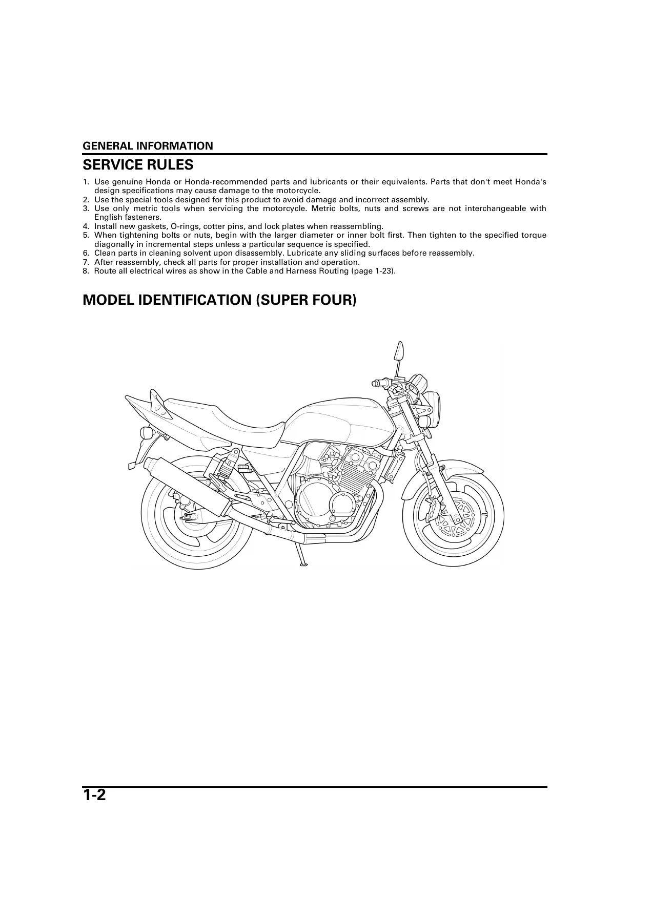
The manual starts with identification and specification material that makes it practical to verify the machine and work from the correct values before beginning a repair. It illustrates the Super Four and Super Bold’ Or versions separately, identifies frame and engine serial-number locations, and presents dimensional, chassis, engine, carburetor, drivetrain, electrical, lubrication, cooling, brake, suspension, and ignition specifications. The engine data in the manual describes a 399.1 cm3 four-cylinder in-line engine with a 55.0 x 42.0 mm bore and stroke, 11.3 : 1 compression ratio, chain-driven DOHC valve train, liquid cooling, and a constant-mesh 6-speed transmission.
Section 1 is particularly useful as a service-data reference. It includes engine-oil capacities, carburetor settings, coolant capacities, valve and piston limits, clutch measurements, crankshaft and transmission limits, front and rear suspension data, hydraulic-brake specifications, battery and charging values, ignition data, standard torque values, component-specific torque values, lubrication and seal points, and extensive cable and harness routing illustrations. Where the document distinguishes variants such as ’04, after ’04, ’04-’05, and after ’05, those distinctions are shown directly in the relevant specification or routing material.
H-VTEC, Immobilizer and System Understanding
The technical-feature chapter explains two systems that are central to this CB400SF service coverage. The immobilizer section shows the relationship between the registered ignition key transponder, immobilizer receiver, immobilizer indicator, and ignition control module. The H-VTEC section explains the change between two-valve and four-valve-per-cylinder operation, the role of the spool valve, the signals used by the ignition control module, and the slide-pin mechanism in the valve lifter assembly. These diagrams and explanations give useful context before moving into maintenance and cylinder-head work involving the VTEC valve components.
Chapters Covered
- 1. General Information
- Service rules and model identification
- General specifications for Super Four and Super Bold’ Or
- Lubrication, fuel and cooling system specifications
- Cylinder head/valve, cylinder/piston and clutch/gearshift specifications
- Crankshaft/transmission and suspension/steering specifications
- Hydraulic brake, battery/charging, ignition and starter specifications
- Standard and engine/frame torque values
- Lubrication and seal points
- Cable and harness routing
- Emission control systems
- 2. Technical Feature
- Immobilizer system
- H-VTEC system
- Spool valve operation
- Slide pin operation
- 3. Frame/Body Panels/Exhaust System
- Service information and troubleshooting
- Seat, seat cowl and side cover
- Fuel tank
- Muffler/exhaust pipe
- Rear fender
- Combination meter cover and front cowl for applicable Super Bold’ Or versions
- 4. Maintenance
- Maintenance schedule
- Fuel line, throttle, choke and air cleaner
- Spark plug and valve clearance
- Engine oil/oil filter
- Carburetor synchronization and engine idle speed
- Radiator coolant and cooling system checks
- Drive chain and drive chain slider
- Brake fluid, brake pads and brake system
- Clutch system, side stand and suspension
- Wheels/tires and steering head bearings
- 5. Lubrication System
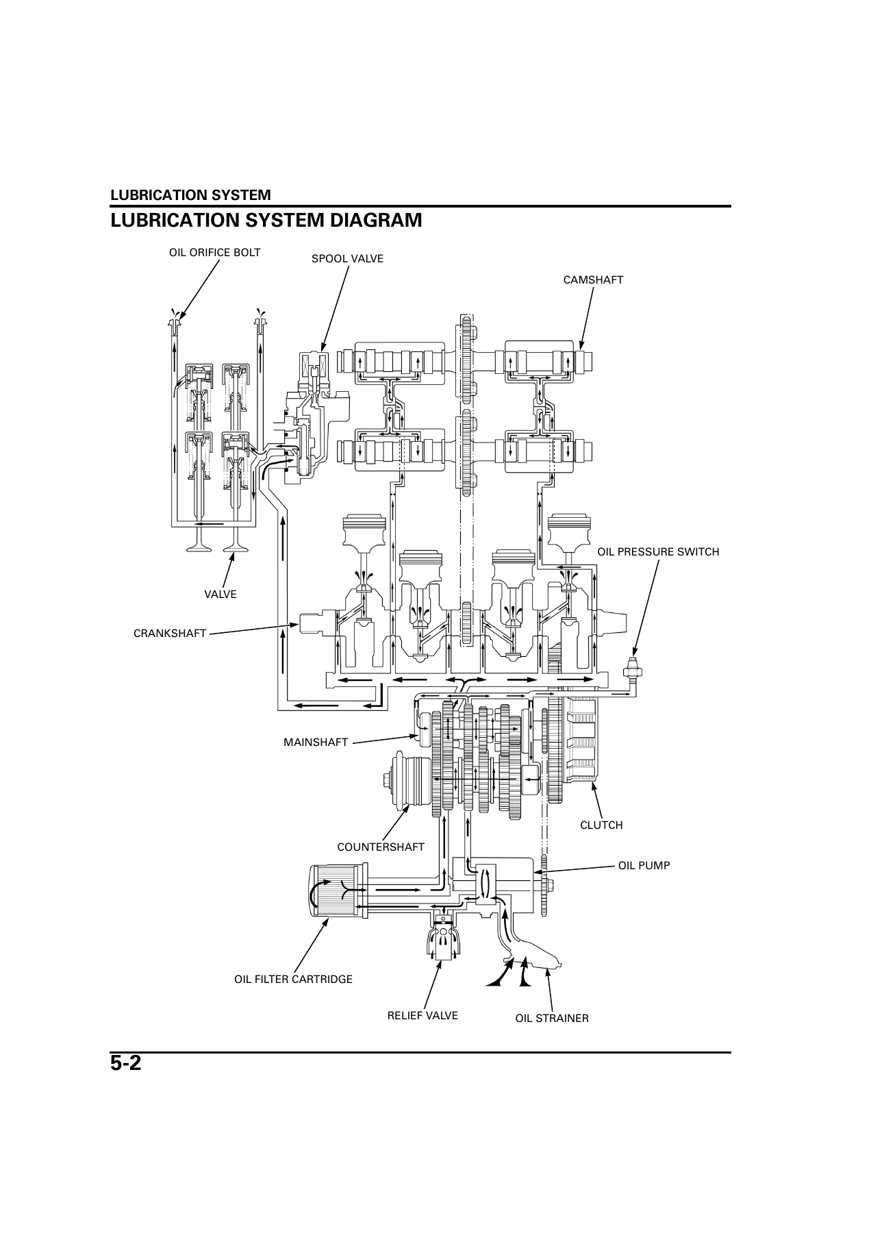
- Lubrication system diagram
- Service information and troubleshooting
- Oil pressure inspection
- Oil strainer and pressure relief valve
- Oil pump removal, inspection, assembly and installation
- 6. Fuel System
- System components and troubleshooting
- Carburetor removal and separation
- Carburetor disassembly and inspection
- Carburetor assembly and combination
- Carburetor installation
- Pilot screw adjustment
- Air cleaner housing and secondary air supply system
- Fuel valve
- 7. Cooling System
- System flow pattern and troubleshooting
- System testing
- Coolant replacement and air bleeding
- Thermostat
- Radiator/cooling fan
- Water pump
- Radiator reserve tank
- 8. Engine Removal/Installation
- System components
- Service information and service data
- Engine removal
- Engine installation
- 9. Cylinder Head/Valve
- System components, service information and troubleshooting
- Cylinder compression test
- Cylinder head cover and camshaft removal
- Cylinder head removal and disassembly
- Valve guide replacement
- Valve seat inspection and refacing
- Cylinder head assembly and installation
- Camshaft and cylinder head cover installation
Taken together, these nine chapters move from identification and service data into the procedures needed to maintain, diagnose, dismantle, inspect, and reassemble major systems covered by this part of the CB400SF manual. The maintenance chapter supplies recurring service procedures and adjustment values, while the lubrication, fuel, and cooling chapters add system-specific troubleshooting and component work. The engine-removal chapter shows the mounting sequence and associated connections, and the cylinder-head chapter reaches into compression testing, camshaft service, H-VTEC valve-related components, valve guides, valve seats, and cylinder-head assembly.
Maintenance, Carburetor and Cooling Procedures
For routine work, the manual provides a maintenance schedule plus procedures for throttle free play, spark plugs, valve clearance, engine oil and filter replacement, carburetor synchronization, idle speed, drive-chain inspection and adjustment, brake-fluid and pad checks, clutch free play, suspension inspection, tire pressures, and steering-head checks. It also lists the special tools used in several procedures, including the oil filter wrench, drive-chain tool set, slide pin stopper, vacuum-gauge adaptors, carburetor float-level gauge, and pilot-screw wrench.
The fuel-system chapter is detailed enough to support more than basic adjustment. It covers removal of the carburetor assembly, separation of the four carburetors, disassembly of the starting enrichment valve, air cut-off valve, vacuum chamber, float chamber, jets and pilot screw, followed by inspection, cleaning, reassembly, combination, installation, synchronization-related setup, and pilot-screw adjustment. Troubleshooting charts address hard starting, lean or rich mixtures, rough idle, afterburn, backfiring, and poor driveability using causes listed in the manual.
Cooling-system coverage follows the coolant circuit through testing and service. Procedures include radiator-cap and system-pressure checks, coolant draining and air bleeding, thermostat inspection, radiator and cooling-fan removal, water-pump inspection and replacement work, and reserve-tank service. The system data includes coolant capacity, radiator-cap relief pressure, thermostat opening temperatures, and the specified coolant mixture.
IMAGES PREVIEW
Cylinder Head and Valve Service Depth
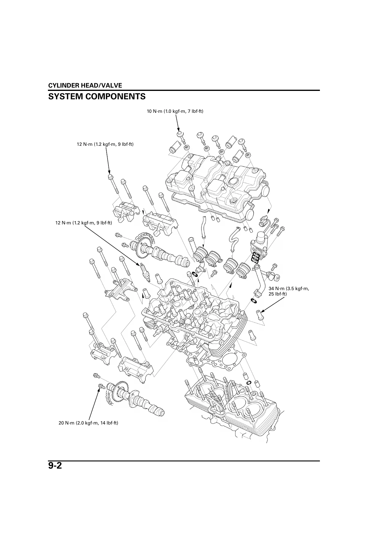
Chapter 9 gives this 2006 Honda CB400SF service manual substantial top-end repair value. It provides cylinder-compression testing, camshaft removal and inspection, camshaft oil-clearance checking, cylinder-head removal, valve-train disassembly, valve-lifter and slide-pin-holder inspection, valve-spring and valve-guide measurements, valve-guide replacement, and valve-seat inspection/refacing. The chapter includes standard dimensions, service limits, torque values, special-tool references, and detailed component illustrations so measurements can be compared with the limits printed in the manual rather than judged by appearance alone.
The H-VTEC-specific hardware is carried into the maintenance and cylinder-head procedures through the VTEC valve lifters, slide pin holders, outer springs, shims, and spool-valve-related information. Valve-clearance inspection and adjustment includes the specified intake and exhaust clearances, crankshaft timing-mark positions, shim measurement, and the calculation used to select a replacement shim.
Use the Correct Procedures for CB400SF Service Work
The 2006 Honda CB400SF Super Four & Super Bold’ Or Service Manual Chapters 1-9 PDF supports a wide range of real workshop jobs: scheduled maintenance, adjustment and inspection, carburetor service, oil-pressure diagnosis, cooling-system repair, engine removal and refitting, compression testing, camshaft work, and cylinder-head/valve service. Having the specified clearances, capacities, torque values, service limits, routing diagrams, troubleshooting paths, and illustrated procedures together helps you carry out the covered work in the sequence and to the measurements given in the manual.
After purchase, the manual is supplied as an instant PDF download with no physical shipping. You can open it on a compatible phone, tablet, laptop, or desktop computer and print the pages you need for workshop reference.
Reviews
There are no reviews yet.