
2006 Yamaha YZFR6V Service Manual – YZF-R6 Repair & Workshop Manual PDF
Original price was: $34.95.$19.95Current price is: $19.95.
Complete 2006 Yamaha YZFR6V service manual for the YZF-R6 — engine, chassis, cooling, fuel injection, electrical and immobilizer procedures with factory torque values, exploded diagrams and the full wiring diagram. Instant PDF download.
Description
The 2006 Yamaha YZFR6V Service Manual is the complete workshop reference produced by Yamaha Motor Company for its dealers and qualified mechanics working on the 2006 YZF-R6. Every major system on the machine is covered — engine, chassis, cooling, fuel injection, electrical and the immobilizer — using step-by-step removal, disassembly, inspection, assembly and installation procedures, with exploded diagrams, factory torque values, service limits and clearance data throughout. Whether you are setting valve clearance, rebuilding the crankcase, synchronizing the YCC-T throttle bodies or chasing a self-diagnostic fault code through the FI system, this YZFR6V service manual gives you the same specifications and sequences that a Yamaha workshop would use.
File Details
- Manual type: Motorcycle service manual (workshop reference)
- Brand: Yamaha
- Model: YZFR6V (2006 YZF-R6)
- Model year: 2006
- Publication number: 2C0281972006
- Language: English
- Format: PDF
- Page count: 437
Chapters Covered
- General Information — vehicle identification, model label, features, FI system outline, YCC-T mechanism and advantages, ECU/CPU structure, multi-function meter operation (clock, odometer, tripmeters, stopwatch, coolant and air intake temperature, self-diagnosis, display brightness and shift timing indicator light control)
- Specifications — general specifications, engine specifications, chassis specifications, electrical specifications, general tightening torques, engine tightening torques, chassis tightening torques, lubrication points and lubricant types, engine oil lubrication chart and lubrication diagrams, cooling system diagrams, cable routing
- Periodic Maintenance — engine (valve clearance, throttle body synchronization, throttle cable free play, spark plugs, compression pressure, engine oil level and change, oil pressure, clutch lever free play, air filter element, throttle body joints, fuel line, crankcase breather hose, exhaust system, EXUP cable adjustment, coolant level and change); chassis (front and rear disc brakes, brake fluid level, brake pads, brake hoses, brake light switch, bleeding the hydraulic system, shift pedal, drive chain slack and lubrication, steering head, front fork, rear shock absorber assembly, tires, wheels, cables, levers, pedals, sidestand, rear suspension); electrical system (battery charging, fuses, headlight bulbs, headlight beam aiming)
- Chassis — front wheel, rear wheel, front brake, rear brake, handlebars, front fork, steering head, rear shock absorber assembly, swingarm, chain drive
- Engine — engine removal and installation, camshafts, cylinder head, valves and valve springs, generator and starter clutch, pickup rotor, electric starter, clutch, shift shaft, oil pump, crankcase, connecting rods and pistons, crankshaft, transmission
- Cooling System — radiator, oil cooler, thermostat, water pump
- Fuel System — fuel tank, fuel pump, air filter case, secondary injectors, throttle bodies, primary injectors, throttle position sensors, air induction system, reed valves
- Electrical System — ignition system, electric starting system, charging system, lighting system, signaling system, cooling system circuit, fuel injection system (ECU self-diagnostic function, self-diagnostic function table, diagnostic mode, troubleshooting details, fault code table, sensor operation table, actuator operation table), fuel pump system, immobilizer system (key registration, code re-registering, self-diagnosis fault codes), electrical components, switch, bulb, fuse, relay, sensor and actuator checks
- Troubleshooting — starting failures, incorrect engine idling speed, poor medium-and-high-speed performance, faulty gear shifting, shift pedal does not move, jumps out of gear, faulty clutch, overheating, overcooling, poor braking performance, faulty front fork legs, unstable handling, faulty lighting or signaling system
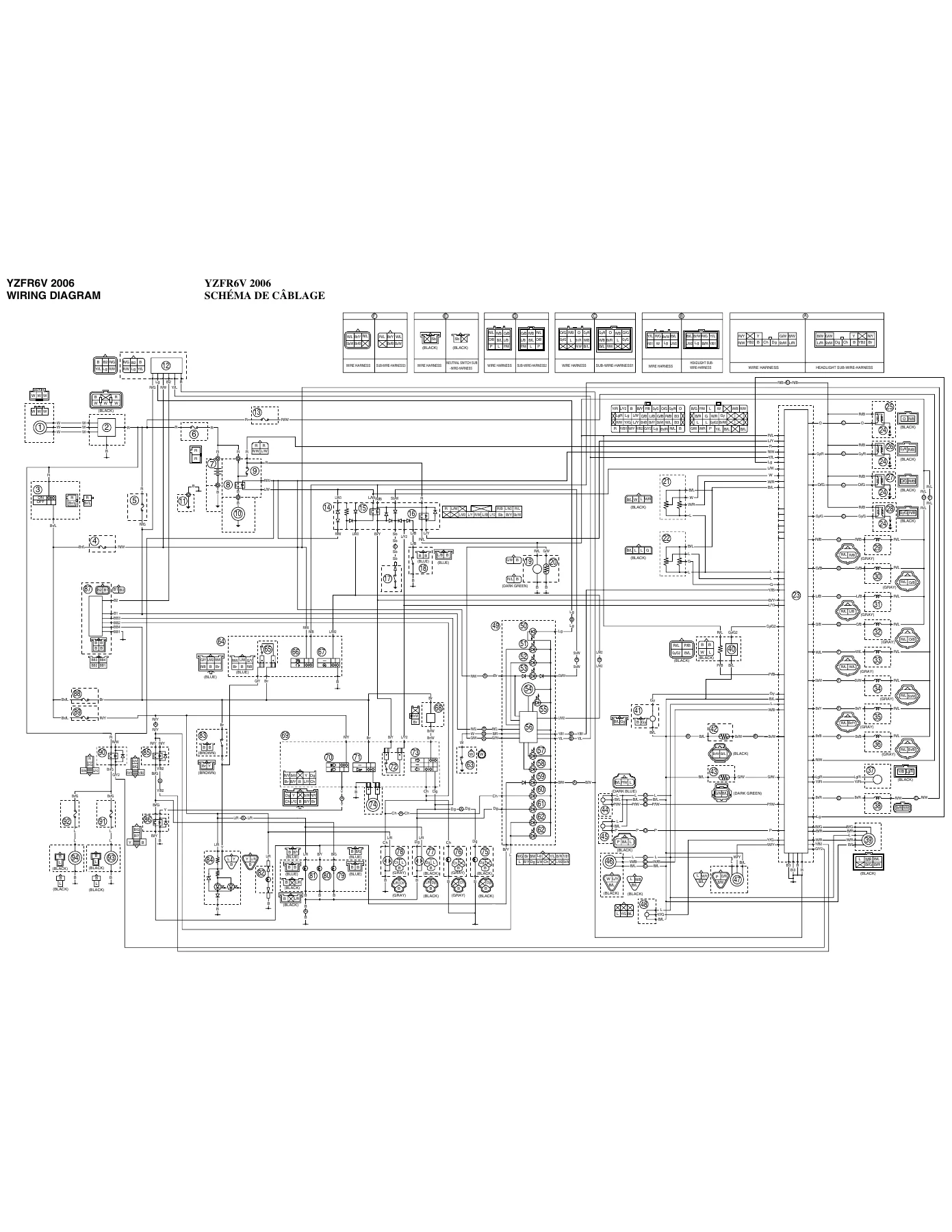
- Wiring Diagram — full-color fold-out style circuit diagram with connector identification, wire colors and color code key
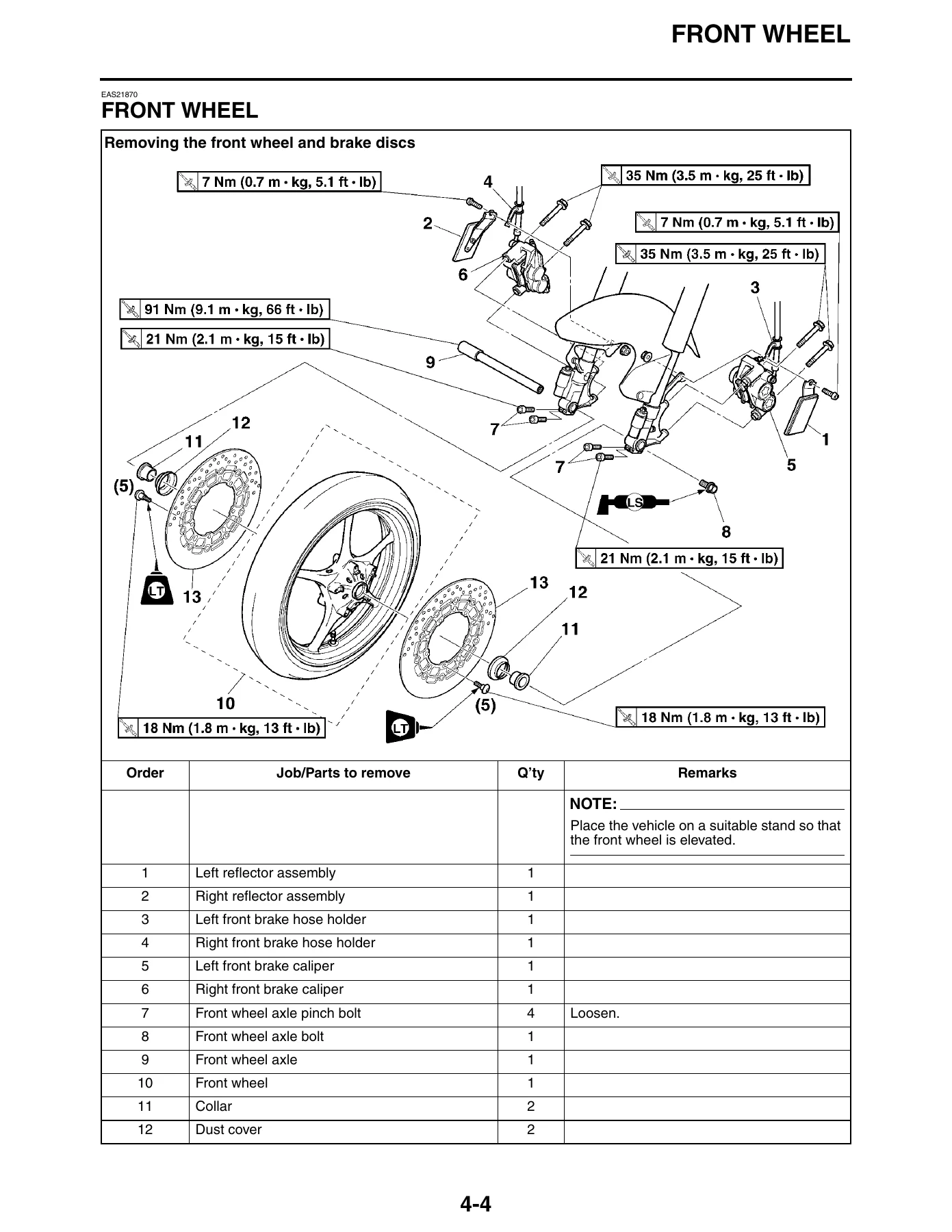
As a whole the document is a complete teardown-to-rebuild reference for a single model. It assumes the reader is already mechanically competent, so it does not waste space on basics — instead it supplies the exact disassembly order, the torque figure for every fastener, the wear limits that tell you when a part is scrap, and the diagnostics that tell you which sensor or circuit is at fault. The exploded diagrams sit next to their job instruction charts so you can see how a component comes apart before you touch it, and the tightening torque tables are split by engine, chassis and standard fastener so you can find the right figure quickly. The electrical section carries the full ECU fault code table with probable causes and diagnostic code numbers, which is what turns a warning light into a repair plan.
What This YZFR6V Workshop Manual Lets You Do
- Set valve clearance correctly on all four cylinders using the measuring sequence, the valve pad thickness tables and the rounding rules shown in the manual
- Synchronize the throttle bodies with a vacuum gauge, including the alternate procedure when the basic method cannot bring the readings within tolerance
- Diagnose the fuel injection system from the ECU self-diagnostic function — read the fault code, look up the probable cause, follow the reinstatement method
- Remove, inspect and rebuild the camshafts, cylinder head, valves, valve springs, valve lifters and valve seats, including the special note on titanium valves
- Rebuild the clutch — friction plate and clutch plate thickness measurement, total assembly width adjustment, clutch boss nut staking, spring free length
- Split the crankcase, measure the crankshaft journal clearances with Plastigauge, select replacement journal bearings from the color code tables
- Remove and reinstall the connecting rods and pistons, select big end bearings from the crankshaft and connecting rod number stampings, and torque the connecting rod nuts to the specified angle
- Disassemble and reassemble the transmission, check shift forks, shift drum and gear dogs, and measure main axle and drive axle runout
- Service the front fork — spring preload, rebound damping, compression damping adjustment, oil level, oil seal and dust seal replacement, damper rod assembly torque
- Set the rear shock absorber spring preload, rebound damping, fast and slow compression damping
- Remove and install the front wheel, rear wheel, brake discs, brake calipers, brake master cylinders and brake hoses, and bleed the hydraulic brake system
- Adjust the drive chain slack, check the 15-link length limit, inspect sprockets and O-rings, and lubricate the chain correctly
- Remove and install the radiator, oil cooler, thermostat and water pump, and change the coolant with the correct mix ratio and capacity
- Remove and install the fuel tank, fuel pump, air filter case, throttle bodies, primary and secondary injectors, and air induction system components
- Check the ignition coils, crankshaft position sensor, lean angle sensor, stator coil, rectifier/regulator, horn, oil level switch, fuel sender, speed sensor, radiator fan motors, coolant temperature sensor, throttle position sensors, air temperature sensor, atmospheric pressure sensor and intake air pressure sensor
- Test fuses, relays, switches and bulb sockets, and read the full wiring diagram with its wire color code key
- Register immobilizer keys and understand the code re-registering requirements if the ECU, immobilizer unit or main switch is replaced
Why It Matters
Sportbike engines at this state of tune are not forgiving of guesswork. Torque values, clearances and adjustment sequences are tied to specific fastener sizes and component materials, and getting them wrong shows up as noise, oil consumption, poor fuelling or a failure that costs far more than the manual. This 2006 Yamaha YZFR6V Service Manual removes that guesswork — the tightening sequences for the cylinder head, crankcase and connecting rod nuts are printed in the order they must be followed, the camshaft cap bolts have an explicit warning about even, crisscross loosening, and the FI diagnostic tables spell out what each fault code actually points to. If you are maintaining your own YZF-R6, running a small workshop, or simply trying to understand what a fault code is telling you, having the manufacturer’s own procedures on hand is the difference between a correct repair and a repeat job.
IMAGES PREVIEW
Instant PDF Delivery
You get the full YZF-R6 2006 service manual as a PDF the moment payment completes — no shipping, no waiting, no physical book to lose in the garage. It opens on any laptop, tablet or phone, and every page is printable so you can take the relevant section out to the bike. Keep it on the workbench screen, print the torque tables, or print the wiring diagram at full size for a fault-tracing job — it is yours to use however suits the job in front of you.
Reviews
There are no reviews yet.