★ TRUSTED BY 321,897+ PROFESSIONALS WORLDWIDE
🏒
Trusted Business
Verified & Licensed
πŸ›‘οΈ
Virus Free Files
100% Safe Downloads
πŸ”’
Secure Payment
SSL Protected
⚑
Instant Delivery
Available Immediately
Sale!

2008-2009 Isuzu N Series Brake Workshop Manual – ABS ASR HSA Repair PDF

Original price was: $34.95.Current price is: $21.95.

Comprehensive 2008/2009MY Isuzu N Series brake workshop manual covering hydraulic brakes, ABS/ASR/EBD, parking brake, and Hill Start Aid. Includes service procedures, diagnostics, specifications, and exploded views for NHR, NLR, NLS, NMR, NNR, NPR, NPS, and NQR models.

⚑
Instant PDF Download
Available immediately
πŸ’Ύ
Save to Your Device
Download & keep forever
πŸ›‘οΈ
Antivirus Scanned
100% virus-free
🌍
Trusted Worldwide
175,000+ customers

Description

2008-2009 Isuzu N Series Brake Workshop Manual

This 2008-2009 Isuzu N Series Brake Workshop Manual is the complete brake section of the 2008/2009MY N Series service documentation. Published by Isuzu Motors Limited in December 2008 as the Fourth Edition, it covers hydraulic brake systems, anti-lock brake systems with anti-slip regulator, parking brakes, and Hill Start Aid for the full range of N Series commercial vehicles including NHR, NLR, NLS, NMR, NNR, NPR, NPS, and NQR models.

File Details

  • Manual Type: Workshop Manual (Brake Section)
  • Brand: Isuzu
  • Model Series: N Series (2008/2009 Model Year)
  • Language: English
  • Page Count: 412 pages
  • File Format: PDF
  • Document Number: LGBRK-WE-0871
  • Edition: Fourth Edition
  • Publication Date: December 2008
  • Publisher: Isuzu Motors Limited, Service Marketing Department

Chapters Covered

  • 4B Brake
    • Hydraulic Brake System β€” Description, Functional Inspection, Primary Specifications
    • Brake Master Cylinder β€” Components, Removal, Disassembly, Reassembly, Installation, Tightening Torques
    • Vacuum Brake Booster β€” Components, Removal, Installation, Inspection, Tightening Torques
    • Hydraulic Brake Booster β€” Description, Maintenance Precautions, Components, Removal, Disassembly, Reassembly, Installation, Adjustment, Tightening Torques
    • Hydraulic Brake Booster Fluid and Filter β€” Components Location Diagram, Removal, Installation
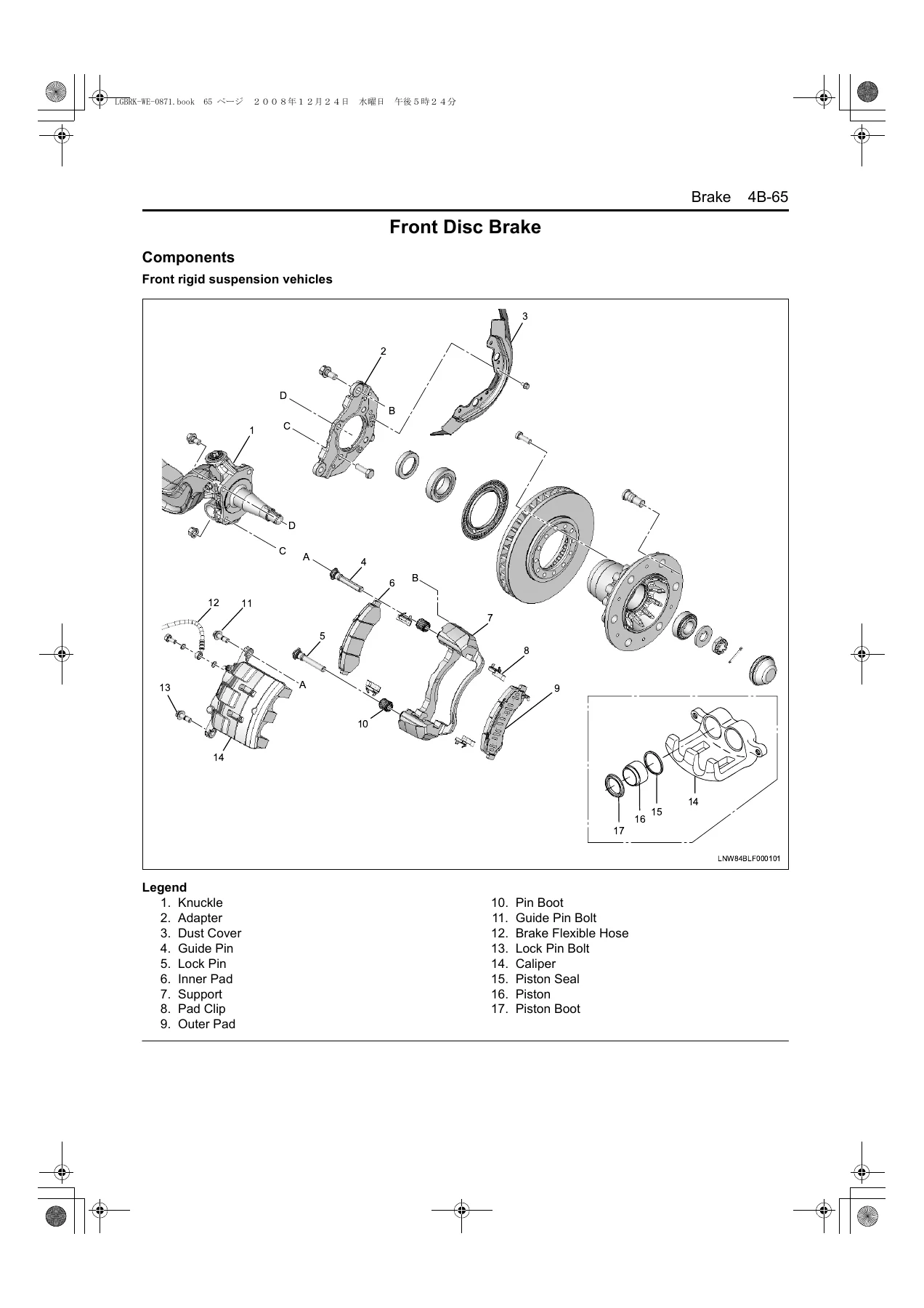
    • Front Disc Brake β€” Components, Removal, Disassembly, Inspection, Reassembly, Installation, Tightening Torques
    • Rear Disc Brake β€” Components, Removal, Disassembly, Inspection, Reassembly, Installation, Tightening Torques
    • Front Drum Brake β€” Components, Removal, Disassembly, Inspection, Reassembly, Installation, Tightening Torques
    • Rear Drum Brake (240/290mm) β€” Components, Removal, Inspection, Installation, Tightening Torques
    • Rear Drum Brake (320mm) β€” Components, Removal, Inspection, Installation, Tightening Torques
    • Rear Drum Brake (370mm) β€” Components, Removal, Disassembly, Inspection, Reassembly, Installation, Primary Specifications, Tightening Torques
    • Rear Drum Brake (with M/AJ) β€” Components, Removal, Disassembly, Reassembly, Installation
    • LSPV (Load Sensing Proportioning Valve) β€” Adjustment
  • 4C1 Anti-Lock Brake (ABS)/Anti-Slip Regulator (ASR)
    • ABS/ASR System β€” Precautions, Description and Operation, Circuit Diagram
    • Procedure of Trouble Diagnosis
    • Trouble Diagnosis Using the Scan Tool
    • Function Inspection List
    • Diagnostic System Check
    • Warning Light/Indicator Light Diagnostics
    • Check List of EHCU Connector Terminal
    • Brake Basic Inspection
    • Diagnostic Trouble Code List and all DTCs
    • Symptom β€” ABS Controls
    • Electronic Hydraulic Control Unit (EHCU) β€” Components, Removal, Installation, Programming
    • Wheel Speed Sensor (Front and Rear)
    • Sensor Rotor (Front and Rear)
    • Sensor Harness (Rear Axle)
    • Master Cylinder Pressure Sensor
    • G Sensor
  • 4D Parking Brake
    • Parking Brake System β€” Description of Function and Operation
    • Special Tool
    • Parking Brake and Parking Brake Lever β€” Components, Removal, Installation
    • Parking Brake (178, 190mm Type) β€” Components, Disassembly, Inspection, Reassembly
    • Parking Brake (203mm Type) β€” Components, Disassembly, Inspection, Reassembly
  • 4E Hill Start Aid (HSA)
    • HSA System β€” Maintenance Precautions, Description of Function and Operation
    • Components Location Diagram, Circuit Diagram
    • Performing the Trouble Diagnosis
    • Trouble Diagnosis Using the Scan Tool
    • Function Inspection List and Diagnostic System Checks
    • HSA Indicator Light Circuit Checks
    • Door Switch, Parking Brake Switch, Stop Light Switch, Neutral Switch Checks
    • HSA Reset Switch, HSA OFF Switch Checks
    • HSA Adjustment
    • Diagnostic Trouble Code List and all DTCs
    • Failure Symptom List
    • HSA Control Unit, HSA Valve, Clutch Stroke Sensor, Clutch Oil Pressure Switch
    • Door Switch, Parking Brake Switch, Stop Light Switch

What This Manual Delivers

This 2008-2009 Isuzu N Series Brake Workshop Manual gives technicians and fleet maintainers the complete brake system service and repair information for the N Series commercial truck range. Every procedure is documented with step-by-step instructions, component illustrations, exploded views, and tightening torque values. The manual covers both vacuum brake booster and hydraulic brake booster configurations, multiple disc and drum brake sizes, and the full ABS/ASR/EBD diagnostic tree with DTC charts.

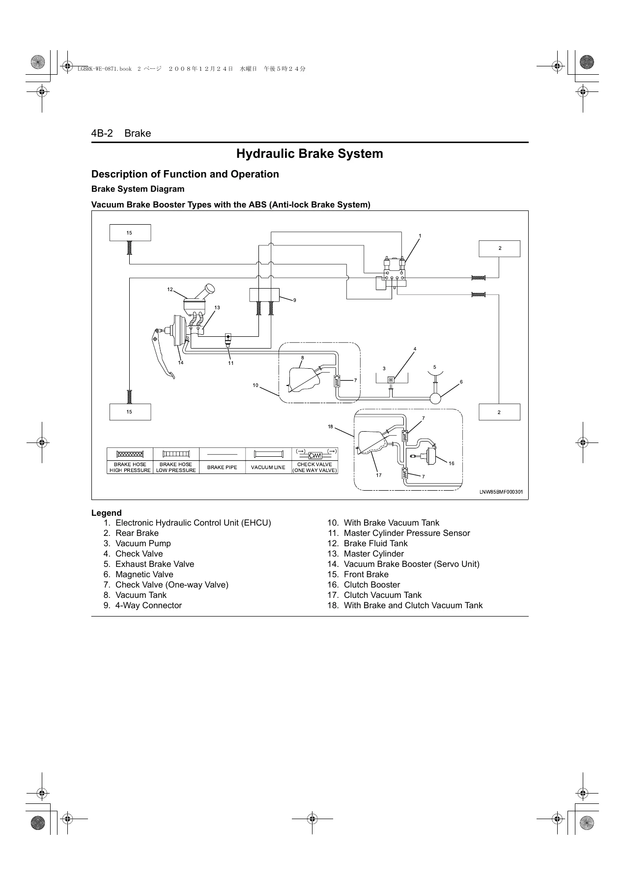
The brake section opens with a complete hydraulic brake system overview including circuit diagrams for vacuum brake booster types with ABS, with LSPV, without ABS and LSPV, and hydraulic brake booster types with and without LSPV. Each brake assembly β€” from the master cylinder and vacuum brake booster to front disc brakes, rear disc brakes, front drum brakes, and four different rear drum brake sizes β€” receives full removal, disassembly, inspection, reassembly, and installation coverage with torque specifications.

For vehicles equipped with anti-lock brakes, the ABS/ASR/EBD section provides comprehensive diagnostic procedures including flash code reading, scan tool usage, DTC charts covering every fault code from C0213 through C0264, and detailed circuit testing for wheel speed sensors, the electronic hydraulic control unit, master cylinder pressure sensor, and G sensor. The parking brake section covers both the 178/190mm and 203mm internal-expanding drum brake types mounted on the transmission rear, with adjustment procedures and return spring specifications.

The Hill Start Aid section is particularly thorough, documenting the HSA system that retains braking force when the driver releases the brake pedal on an incline. It includes the full diagnostic trouble code list (DTC 03 through 91), scan tool data tables with typical values, circuit checks for every input component including door switches, parking brake switch, stop light switch, neutral switch, clutch stroke sensor, and clutch oil pressure switch, plus the HSA adjustment procedure for both initial adjustment and brake release fine-tuning.

Covered Models

This manual applies to the following 2008/2009 Isuzu N Series models: NHR, NLR, NLS, NMR, NNR, NPR, NPS, and NQR. The ABS/ASR section references both the 4HK1 and 4JJ1 engine control module communications, and the brake specifications cover multiple front and rear brake configurations including disc and drum variants across these models.

Why This Manual Matters for Your Workshop

Brake system repair on commercial vehicles demands exact procedures and correct torque values β€” mistakes affect safety directly. This 2008-2009 Isuzu N Series Brake Workshop Manual provides the precise specifications, component identification, and diagnostic flow charts needed to service these systems correctly. Whether you are replacing a master cylinder, rebuilding a rear drum brake, diagnosing an ABS warning light, or adjusting a Hill Start Aid release point, the procedures in this manual are the ones used for these vehicles.

Complete PDF Bookmark Tree

Complete Bookmarks

The complete bookmarks in the β€œ2008-2009 Isuzu N Series Brake Workshop Manual – ABS ASR HSA Repair PDF” are as follows:

BRAKESp. 1
Brakep. 4
Hydraulic Brake Systemp. 5
Description of Function and Operationp. 5
Functional Inspectionp. 27
Primary Specificationsp. 38
Special Toolp. 41
Brake Master Cylinderp. 42
Componentsp. 42
Removalp. 42
Disassemblyp. 43
Reassemblyp. 44
Installationp. 46
List of Tightening Torquesp. 47
Vacuum Brake Boosterp. 48
Componentsp. 48
Removalp. 49
Installationp. 50
Inspectionp. 52
List of Tightening Torquesp. 54
Hydraulic Brake Boosterp. 55
Description of Function and Operationp. 55
Maintenance Precautionsp. 57
Componentsp. 59
Removalp. 59
Disassemblyp. 61
Reassemblyp. 62
Installationp. 63
Adjustmentp. 64
List of Tightening Torquesp. 66
Hydraulic Brake Booster Fluid and Filterp. 67
Components Location Diagramp. 67
Removalp. 67
Installationp. 67
Front Disc Brakep. 68
Componentsp. 68
Removalp. 70
Disassemblyp. 71
Inspectionp. 72
Reassemblyp. 72
Installationp. 74
List of Tightening Torquesp. 76
Rear Disc Brakep. 79
Componentsp. 79
Removalp. 80
Disassemblyp. 80
Inspectionp. 81
Reassemblyp. 81
Installationp. 83
List of Tightening Torquesp. 85
Front Drum Brakep. 86
Componentsp. 86
Removalp. 90
Disassemblyp. 93
Inspectionp. 95
Reassemblyp. 96
Installationp. 98
List of Tightening Torquesp. 100
Rear Drum Brake(with A/AJφ240/290mm(9.45/11.42in)p. 101
Componentsp. 101
Removalp. 101
Inspectionp. 104
Installationp. 106
List of Tightening Torquesp. 108
Rear Drum Brake(with A/AJ Ο†320mm(12.60in))p. 110
Componentsp. 110
Removalp. 110
Inspectionp. 113
Installationp. 114
List of Tightening Torquesp. 117
Rear Drum Brake(with A/AJ Ο†370mm(14.57in))p. 118
Componentsp. 118
Removalp. 118
Disassemblyp. 120
Inspectionp. 122
Reassemblyp. 124
Installationp. 126
Primary Specificationsp. 127
List of Tightening Torquesp. 128
Rear Drum Brake (with M/AJ)p. 129
Componentsp. 129
Removalp. 129
Disassemblyp. 132
Reassemblyp. 133
Installationp. 134
LSPV (Load Sensing Proportioning Valve)p. 137
Adjustmentp. 137
Anti-Lock Brake (ABS)/Anti-Slip Regulator (ASR)p. 140
ABS/ASR Systemp. 141
Precautions for servicingp. 141
Description and Operationp. 142
Circuit Diagramp. 154
Procedure of Trouble Diagnosisp. 157
Trouble Diagnosis Using the Scan Toolp. 165
Function Inspection Listp. 171
Diagnostic System Check-Anti-lock Brake System (ABS) Controlsp. 172
Scan Tool Does Not Communicate with Class 2 Devicep. 174
Warning Light/ Indicator Light Does Not Turn Onp. 176
Warning Light/ Indicator Light Remains Onp. 183
Warning Light Repeatedly Blinksp. 189
Check List of Electronic Hydraulic Control Unit (EHCU) Connector Terminalp. 192
Brake Basic Inspectionp. 195
Diagnostic Trouble Code Listp. 196
DTC C0213 (Flash Code 13)p. 197
DTC C0214 (Flash Code 14)p. 199
DTC C0215 (Flash Code 15)p. 200
DTC C0216 (Flash Code 16)p. 202
DTC C0221 (Flash Code 21)p. 206
DTC C0222 (Flash Code 22)p. 210
DTC C0224 (Flash Code 24)p. 216
DTC C0226 (Flash Code 26)p. 218
DTC C0233 (Flash Code 33)p. 221
DTC C0234 (Flash Code 34)p. 223
DTC C0235 (Flash Code 35)p. 224
DTC C0241 (Flash Code 41)p. 226
DTC C0243 (Flash Code 43)p. 228
DTC C0245 (Flash Code 45)p. 229
DTC C0251 (Flash Code 51)p. 231
DTC C0252 (Flash Code 52)p. 234
DTC C0253 (Flash Code 53)p. 237
DTC C0254 (Flash Code 54)p. 240
DTC C0261 (Flash Code 61)p. 243
DTC C0262 (Flash Code 62)p. 245
DTC C0263 (Flash Code 63)p. 247
DTC C0264 (Flash Code 64)p. 249
Symptom – ABS Controlsp. 251
Intermittentp. 252
ABS works frequently but the brake is not effective or ASR operates frequentlyp. 255
ABS works frequently but the brake is not effective or ASR operates frequentlyp. 256
Uneven braking occurs while ABS worksp. 257
Uneven braking occurs while ABS worksp. 258
The wheels lock when brakingp. 259
Brake pedal feeling is abnormalp. 260
Brake operation sounds are heard from the hydraulic unit even though the brake is not appliedp. 262
Special Toolp. 264
Electronic Hydraulic Control Unit (EHCUοΌ‰p. 265
Componentsp. 265
Removalp. 265
Installationp. 267
Programmingp. 268
Wheel Speed Sensor (Front)p. 270
Componentsp. 270
Removalp. 270
Installationp. 271
Inspectionp. 271
Sensor Rotor (Front)p. 273
Componentsp. 273
Removalp. 273
Installationp. 273
Sensor Harness (Rear Axle) (DrumBrake)p. 275
Componentsp. 275
Removalp. 275
Installationp. 275
Sensor Harness (Rear Axle) (Disc Brake)p. 277
Componentsp. 277
Removalp. 277
Installationp. 277
Wheel Speed Sensor (Rear) (Drum Brake)p. 279
Componentsp. 279
Removalp. 279
Installationp. 280
Inspectionp. 280
Wheel Speed Sensor (Rear) (Disc Brake)p. 281
Componentsp. 281
Removalp. 281
Installationp. 282
Inspectionp. 283
Sensor Rotor (Rear) (Drum Brake)p. 284
Componentsp. 284
Removalp. 284
Installationp. 284
Sensor Rotor (Rear) (Disc Brake)p. 285
Componentsp. 285
Removalp. 285
Installationp. 286
Master Cylinder Pressure Sensorp. 287
Removalp. 287
Installationp. 287
G Sensorp. 288
Removalp. 288
Installationp. 288
Inspectionp. 288
Parking Brakep. 290
Parking Brake Systemp. 291
Description of Function and Operationp. 291
Special Toolp. 292
Parking Brake and Parking Brake Leverp. 293
Componentsp. 293
Removalp. 293
Installationp. 295
Parking Brake (178, 190mm (7.01, 7.48in) Type)p. 298
Componentsp. 298
Disassemblyp. 298
Inspectionp. 298
Reassemblyp. 300
Parking Brake (203mm (7.99in) Type)p. 301
Componentsp. 301
Disassemblyp. 301
Inspectionp. 302
Reassemblyp. 303
Hill Start Aid (HSA)p. 304
HSA Systemp. 305
Maintenance Precautionsp. 305
Description of Function and Operationp. 306
Components Location Diagramp. 312
Circuit Diagramp. 314
Performing the Trouble Diagnosisp. 316
Trouble diagnosis using the scan toolp. 325
Function Inspection Listp. 329
Diagnostic System Check – Hill Start Aids (HSA) Controlsp. 330
HSA Indicator Light Illuminating Circuit System Checkp. 333
HSA Indicator Light Blinking Circuit System Checkp. 337
HSA Control Unit Power/ Ground Circuit System Checkp. 339
Scan Tool Circuit System Checkp. 342
Door Switch System Checkp. 344
Parking Brake Switch System Checkp. 347
Stop Light Switch System Checkp. 350
Neutral Switch System Checkp. 354
HSA Reset Switch System Checkp. 357
HSA OFF Switch System Checkp. 360
HSA Adjustmentp. 363
Diagnostic Trouble Code Listp. 364
DTC 03p. 365
DTC 08p. 367
DTC 19p. 371
DTC 25p. 373
DTC 33p. 377
DTC 36p. 378
DTC 86p. 380
DTC 91p. 383
Failure Symptom Listp. 386
The HSA Does Not Operatep. 387
HSA Is Not Cancelled Even If the HSA OFF Switch Is Pressedp. 389
HSA Is Not Cancelled Even If the Start Operation Is Performed (HSA indicator light continues to b…p. 391
HSA Is Not Cancelled Even When the Parking Brake Lever Is Engagedp. 393
When HSA Is Operating, the Buzzer Does Not Sound Even If the Door Is Openedp. 395
When Performing Trouble Diagnosis, the HSA Indicator Light Blinks and the DTC Is Not Displayedp. 397
HSA Indicator Light Has Blinked and the Buzzer Has Sounded In the Past (currently normal)p. 398
Special Toolp. 400
HSA Control Unitp. 401
Removalp. 401
Installationp. 401
HSA Valvep. 402
Removalp. 402
Installationp. 402
Clutch Stroke Sensorp. 403
Removalp. 403
Inspectionp. 403
Adjustmentp. 403
Clutch Oil Pressure Switchp. 404
Removalp. 404
Installationp. 404
HSA OFF Switch, Adjustment Switch and Reset Switchp. 405
Removalp. 405
Inspectionp. 405
Installationp. 405
Neutral Switchp. 406
Removalp. 406
Inspectionp. 406
Installationp. 406
Door Switchp. 407
Removalp. 407
Inspectionp. 407
Installationp. 407
Parking Brake Switchp. 408
Removalp. 408
Functional Inspectionp. 408
Installationp. 408
Stop Light Switchp. 409
Removalp. 409
Installationp. 409

The ABS/ASR section alone includes 14 diagnostic trouble codes with full circuit/system testing charts, making it possible to pinpoint faults in the wheel speed sensor circuits, solenoid valves, motor circuits, CAN communication, and sensor signal circuits rather than replacing parts by guesswork. The hydraulic brake booster section covers the unique accumulator and charge valve system used on certain N Series configurations, with explicit safety precautions for handling high-pressure hydraulic oil.

With 412 pages of brake-specific service information, this PDF is an essential reference for any technician or fleet workshop maintaining Isuzu N Series trucks from the 2008 and 2009 model years.

IMAGES PREVIEW

2008-2009 Isuzu N Series Brake Workshop Manual - ABS ASR HSA Repair PDF β€” PDF page 1 preview
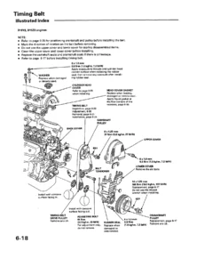
2008-2009 Isuzu N Series Brake Workshop Manual - ABS ASR HSA Repair PDF β€” PDF page 5 preview
2008-2009 Isuzu N Series Brake Workshop Manual - ABS ASR HSA Repair PDF β€” PDF page 68 preview

Instant PDF Delivery

This Isuzu N Series brake workshop manual is delivered as an instant PDF download after payment. No shipping, no waiting. The file works on any device β€” computer, tablet, or smartphone β€” and pages can be printed for use in the workshop. Keep it on your service laptop or print the sections you need for the job at hand.
Reviews

There are no reviews yet.

Be the first to review “2008-2009 Isuzu N Series Brake Workshop Manual – ABS ASR HSA Repair PDF”

What Our Customers Say

β˜…β˜…β˜…β˜…β˜… Live reviews from customers
Loading customer reviews...
0
    0
    Your Cart
    Your cart is emptyReturn to Shop
    πŸ›’
    Recently Purchased
    πŸ•’ verified order