Description
2008 Yamaha Rhino YXR70FX Service Manual – LIT-11616-21-58
This 2008 Yamaha Rhino YXR70FX Service Manual is the complete workshop reference for the YXR70FX side-by-side utility vehicle, covering the 686cc liquid-cooled four-stroke engine, fuel injection system, drive train, chassis, and electrical systems. Published under document number LIT-11616-21-58, this first edition (September 2007) gives mechanics and owners the procedures, specifications, and diagrams needed to service the Rhino 700 from routine maintenance through complete engine disassembly.
File Details
- Manual type: Service Manual
- Brand: Yamaha
- Model: Rhino YXR70FX
- Language: English
- Page count: ~498 pages
- File format: PDF
- Document number: LIT-11616-21-58
- Edition: First edition, September 2007
- Publication: Printed in U.S.A.
Chapters Covered
- General Information — vehicle identification, model label, features, instrument functions, preparation for removal and disassembly, replacement parts, gaskets and seals, lock washers, bearings, circlips, checking connections, special tools
- Specifications — general specifications, engine specifications, chassis specifications, electrical specifications, tightening torques, lubrication points and lubricant types, coolant flow diagrams, oil flow diagrams, cable routing
- Periodic Checks and Adjustments — maintenance chart, valve clearance, throttle cable, spark plug, ignition timing, compression pressure, engine oil level and change, air filter element, throttle body joint, fuel hose, breather hoses, coolant level and change, cooling system, coolant temperature warning light, V-belt, exhaust system, spark arrester, brake pedal, parking brake, brake fluid, front and rear brake pads, brake hoses and pipes, bleeding the hydraulic brake system, select lever shift rod, brake light switch, final gear oil, differential gear oil, CV joint dust boots, steering system, toe-in, front and rear shock absorbers, tires, wheels, cables, pedals, battery, fuses, headlight beams and bulbs, tail/brake light bulb
- Engine — engine removal, V-belt cooling ducts, muffler and exhaust pipes, shift arm, hoses and leads, engine mounting bolts, installing the engine, cylinder head, camshaft sprocket, tappet covers, timing chain tensioner, rocker arms and camshaft, valves and valve springs, cylinder and piston, AC magneto, balancer gears and oil pump gears, primary and secondary sheaves, clutch, crankcase, timing chain and oil filter, crankshaft and oil pump, transmission, middle gear
- Cooling System — radiator and coolant reservoir, thermostat, water pump, oil cooler
- Fuel Injection System — circuit diagram, ECU self-diagnostic function, self-diagnostic function table, troubleshooting chart, diagnostic mode, diagnostic code table, sensor operation table, actuator operation table, troubleshooting details, intake air pressure sensor, intake air temperature sensor, air filter case and air intake duct, fuel pump and fuel tank, throttle body, checking the fuel injector, checking and adjusting the throttle position sensor, checking fuel pump and pressure regulator operation
- Drive Train — troubleshooting, checking noises, front constant velocity joints, differential gear and drive shaft, rear constant velocity joints, final drive gear and drive shaft, measuring and adjusting differential gear lash and final gear lash, positioning final drive pinion gear and ring gear
- Chassis — seats, enclosure, hood and cargo bed, front guard, side doors, panels and front console, skid plates, enclosure and seat belts, front and rear wheels, front and rear brakes, brake master cylinder, front brake caliper, rear brake calipers, parking brake, pedal assembly, steering system, tie-rod and steering knuckle, front arms and front shock absorbers, rear knuckle and stabilizer, rear arms and rear shock absorber
- Electrical — electrical components, checking switch continuity, checking switches, checking bulbs and bulb sockets, ignition system, electric starting system, starter motor, charging system, lighting system, signaling system, cooling system circuit, fuel pump system, 2WD/4WD selecting system
- Troubleshooting — starting failure/hard starting, poor idle speed performance, poor medium and high-speed performance, faulty drive train, faulty gear shifting, faulty clutch performance, overheating, overcooling, faulty brake, shock absorber malfunction, unstable handling, lighting system
Complete PDF Bookmark Tree
Complete Bookmarks
The complete bookmarks in the “2008 Yamaha Rhino YXR70FX Service Manual – LIT-11616-21-58” are as follows:
+2008 Rhino Fuel Injection 700FI YXR70FX Service Manualp. 1
+Importantp. 3
Important Informationp. 3
+How To Use This Manualp. 4
Manual Organizationp. 4
Exploded Diagramsp. 4
Symbolsp. 5
Table Of Contentsp. 7
+Chapter 1 General Informationp. 8
+General Informationp. 20
+Vehicle Identificationp. 20
Vehicle Identification Numberp. 20
Model Labelp. 20
+Featuresp. 21
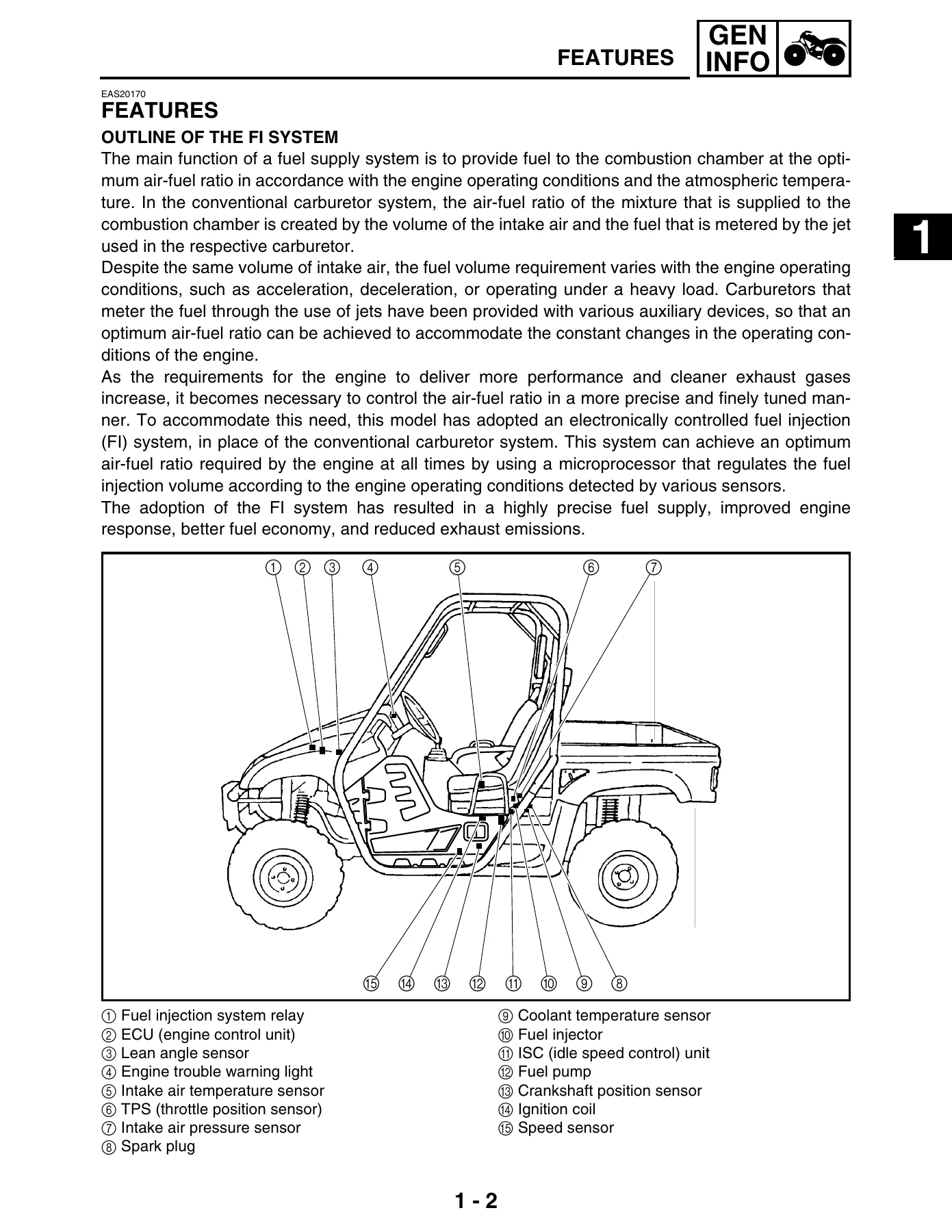
Outline Of The FI Systemp. 21
FI Systemp. 22
Instrument Functionsp. 23
+Important Informationp. 26
Preparation For Removal And Disassemblyp. 26
Replacement Partsp. 26
Gaskets, Oil Seals And O-ringsp. 26
Lock Washers/Plates And Cotter Pinsp. 27
Bearings And Oil Sealsp. 27
Circlipsp. 27
Checking The Connectionsp. 28
Special Toolsp. 29
+Chapter 2 Specificationsp. 8
+Specificationsp. 36
General Specificationsp. 36
Engine Specificationsp. 40
Chassis Specificationsp. 47
Electrical Specificationsp. 50
+Tightening Torquesp. 52
Engine Tightening Torquesp. 52
Chassis Tightening Torquesp. 55
How To Use The Conversion Tablep. 59
General Tightening Torque Specificationsp. 59
+Lubrication Points And Lubricant Typesp. 60
Coolant Flow Diagramsp. 62
Oil Flow Diagramsp. 64
Cable Routingp. 67
+Chapter 3 Periodic Checks And Adjustmentsp. 9
+Periodic Checks And Adjustmentsp. 85
Introductionp. 85
Periodic Maintenance Chart For The Emission Control Systemp. 85
General Maintenance And Lubrication Chartp. 86
+Enginep. 87
Adjusting The Valve Clearancep. 87
Adjusting The Throttle Cablep. 90
Checking The Spark Plugp. 91
Checking The Ignition Timingp. 93
Measuring The Compression Pressurep. 94
Checking The Engine Oil Levelp. 97
Changing The Engine Oilp. 98
Cleaning The Air Filter Elementp. 100
Checking The Throttle Body Jointp. 103
Checking The Fuel Hosep. 103
Checking The Breather Hosesp. 103
Checking The Coolant Levelp. 104
Changing The Coolantp. 105
Checking The Cooling Systemp. 109
Checking The Coolant Temperature Warning Lightp. 110
Checking And Replacing The V-beltp. 111
Checking The Exhaust Systemp. 112
Cleaning The Spark Arresterp. 113
+Chassisp. 114
Adjusting The Brake Pedalp. 114
Adjusting The Parking Brakep. 115
Checking The Brake Fluid Levelp. 116
Checking The Front Brake Padsp. 117
Checking The Rear Brake Padsp. 118
Checking The Parking Brake Padsp. 118
Checking The Brake Hoses And Brake Pipesp. 119
Bleeding The Hydraulic Brake Systemp. 120
Adjusting The Select Lever Shift Rodp. 121
Adjusting The Brake Light Switchp. 122
Checking The Final Gear Oil Levelp. 122
Changing The Final Gear Oilp. 123
Checking The Differential Gear Oilp. 124
Changing The Differential Gear Oilp. 125
Checking The Constant Velocity Joint Dust Bootsp. 127
Checking The Steering Systemp. 127
Adjusting The Toe-inp. 128
Adjusting The Front Shock Absorbersp. 129
Adjusting The Rear Shock Absorbersp. 132
Checking The Tiresp. 135
Checking The Wheelsp. 137
Checking And Lubricating The Cablesp. 138
Lubricating The Pedals, Etc.p. 138
+Electrical Systemp. 139
Checking And Charging The Batteryp. 139
Checking The Fusesp. 145
Adjusting The Headlight Beamsp. 148
Changing The Headlight Bulbsp. 148
Changing The Tail/Brake Light Bulbp. 149
+Chapter 4 Enginep. 10
+Enginep. 151
+Engine Removalp. 151
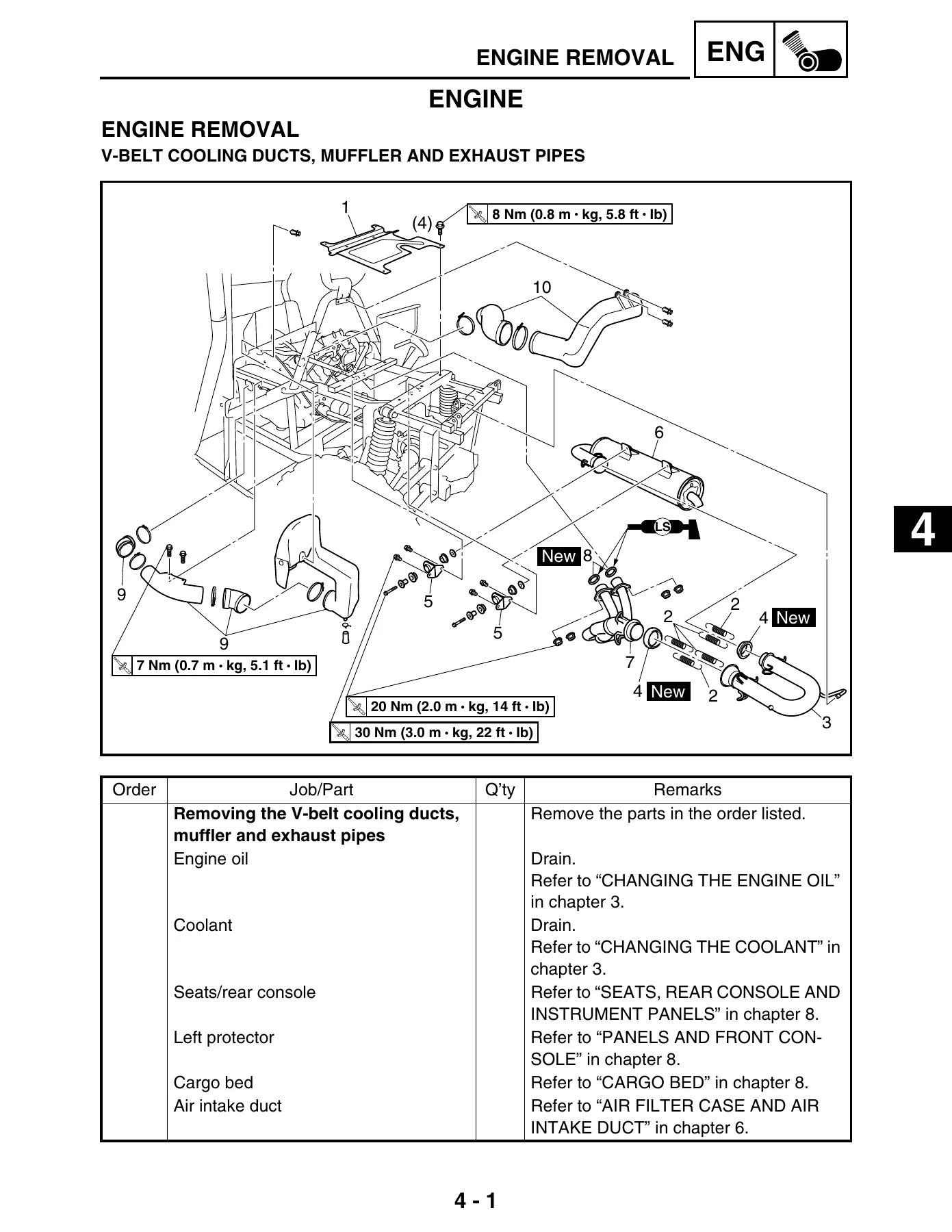
V-belt Cooling Ducts, Muffler And Exhaust Pipesp. 151
Installing The V-belt Cooling Ductsp. 154
Shift Armp. 155
Hoses And Leadsp. 156
Engine Mounting Boltsp. 158
Installing The Enginep. 160
+Cylinder Headp. 161
Removing The Cylinder Headp. 164
Checking The Camshaft Sprocketp. 165
Checking The Tappet Coversp. 165
Checking The Timing Chain Tensionerp. 165
Checking The Cylinder Headp. 166
Installing The Cylinder Headp. 167
+Rocker Arms And Camshaftp. 170
Removing The Rocker Arms And Camshaftp. 172
Checking The Camshaftp. 172
Checking The Decompression Systemp. 173
Checking The Rocker Arms And Rocker Arm Shaftsp. 173
Installing The Camshaft And Rocker Armsp. 174
+Valves And Valve Springsp. 177
Removing The Valves And Valve Springsp. 178
Checking The Valves And Valve Springsp. 179
Installing The Valves And Valve Springsp. 183
+Cylinder And Pistonp. 186
Removing The Pistonp. 187
Checking The Cylinder And Pistonp. 187
Checking The Piston Ringsp. 189
Checking The Piston Pinp. 190
Installing The Piston And Cylinderp. 191
+AC Magnetop. 194
Removing The AC Magneto Rotorp. 197
Checking The Stator Coil And Crankshaft Position Sensorp. 198
Checking The Starter Clutchp. 198
Checking The Torque Limiterp. 199
Installing The AC Magneto Rotorp. 199
+Balancer Gears And Oil Pump Gearsp. 201
Removing The Balancer Driven Gear And Oil Pump Driven Gearp. 203
Checking The Oil Pump Drivep. 203
Checking The Balancer Drivep. 203
Installing The Balancer Drive Gear, Balancer Driven Gear, And Oil Pump Driven Gearp. 204
+Primary And Secondary Sheavesp. 205
Primary Sheavep. 207
Secondary Sheavep. 208
Removing The Primary And Secondary Sheavesp. 209
Disassembling The Secondary Sheavep. 209
Checking The Primary Sheavep. 210
Checking The Secondary Sheavep. 210
Assembling The Primary Sheavep. 211
Assembling The Secondary Sheavep. 212
Installing The Primary And Secondary Sheavesp. 214
+Clutchp. 215
Removing The Clutchp. 217
Checking The Clutchp. 218
Installing The Clutchp. 219
+Crankcasep. 220
Timing Chain And Oil Filterp. 220
Crankcasep. 222
Crankcase Bearingsp. 223
Separating The Crankcasep. 224
Checking The Timing Chain And Guidep. 224
Checking The Relief Valvep. 224
Checking The Bearingsp. 225
Checking The Crankcasep. 225
Assembling The Crankcasep. 225
Installing The Shift Leverp. 226
+Crankshaft And Oil Pumpp. 227
Oil Pumpp. 228
Removing The Crankshaftp. 229
Checking The Oil Pumpp. 229
Checking The Oil Strainerp. 230
Checking The Crankshaftp. 230
Assembling The Oil Pumpp. 231
Installing The Crankshaftp. 231
+Transmissionp. 233
Drive Axlep. 235
Removing The Transmissionp. 237
Checking The Shift Forksp. 237
Checking The Shift Drump. 238
Checking The Transmissionp. 238
Checking The Secondary Shaftp. 239
Assembling The Shift Fork Assemblyp. 239
Installing The Transmissionp. 239
+Middle Gearp. 241
Middle Drive Shaftp. 241
Middle Driven Shaftp. 242
Removing The Middle Drive Shaftp. 244
Removing The Middle Driven Shaftp. 245
Checking The Pinion Gearsp. 248
Selecting Middle Drive And Driven Gear Shimsp. 248
Installing The Bearing And Oil Sealsp. 252
Installing The Middle Driven Shaftp. 253
Installing The Middle Drive Shaftp. 255
Measuring The Middle Gear Backlashp. 256
+Chapter 5 Cooling Systemp. 13
+Cooling Systemp. 257
+Radiator And Coolant Reservoirp. 257
Checking The Radiatorp. 259
Installing The Radiatorp. 260
+Thermostatp. 261
Checking The Thermostatp. 262
Installing The Thermostatp. 262
+Water Pumpp. 263
Disassembling The Water Pumpp. 265
Checking The Water Pumpp. 265
Assembling The Water Pumpp. 266
+Oil Coolerp. 268
Checking The Oil Coolerp. 270
+Chapter 6 Fuel Injection Systemp. 13
+Fuel Injection Systemp. 271
+Fuel Injection Systemp. 271
Circuit Diagramp. 272
ECU Self-Diagnostic Functionp. 274
Self-Diagnostic Function Tablep. 275
Troubleshooting Chartp. 276
Diagnostic Modep. 277
Troubleshooting Detailsp. 281
Checking The Intake Air Pressure Sensorp. 296
Checking The Intake Air Temperature Sensorp. 296
+Air Filter Case And Air Intake Ductp. 298
Installing The Air Intake Duct And Air Filter Casep. 301
+Fuel Pump And Fuel Tankp. 302
Removing The Fuel Tankp. 304
Removing The Fuel Pumpp. 304
Checking The Fuel Pump Bodyp. 305
Checking The Rollover Valvep. 305
Installing The Fuel Pumpp. 305
Installing The Fuel Hosep. 306
+Throttle Bodyp. 307
Removing The Throttle Body Assemblyp. 310
Checking The Fuel Injectorp. 310
Checking The Throttle Bodyp. 310
Installing The Throttle Body Assemblyp. 311
Checking The Fuel Pump And Pressure Regulator Operationp. 313
Checking And Adjusting The Throttle Position Sensorp. 314
+Chapter 7 Drive Trainp. 14
+Drive Trainp. 316
+Troubleshootingp. 316
Checking Noisesp. 316
Troubleshooting Chartp. 318
+Front Constant Velocity Joints, Differential Gear And Drive Shaftp. 319
Disassembling The Front Constant Velocity Jointsp. 325
Disassembling The Universal Jointp. 326
Removing The Differential Gear Assemblyp. 326
Checking The Front Constant Velocity Jointsp. 327
Checking The Differential Gearsp. 327
Checking The Differential Gear Motorp. 328
Assembling The Front Constant Velocity Jointsp. 328
Assembling The Differential Gearsp. 330
Assembling The Universal Jointp. 332
Measuring The Differential Gear Lashp. 332
Adjusting The Differential Gear Lashp. 333
Checking The Differential Gear Operationp. 334
+Rear Constant Velocity Joints, Final Drive Gear And Drive Shaftp. 335
Disassembling The Rear Constant Velocity Jointsp. 343
Assembling The Rear Constant Velocity Jointsp. 344
Disassembling The Final Gear Casep. 346
Removing The Final Drive Roller Bearingsp. 347
Installing The Final Drive Roller Bearingsp. 347
Positioning The Final Drive Pinion Gear And Ring Gearp. 348
Checking The Drive Shaftp. 353
Checking The Final Gear Casep. 353
Measuring And Adjusting The Final Gear Lashp. 353
Assembling The Final Gear Casep. 355
+Chapter 8 Chassisp. 15
+Chassisp. 358
+Seats, Enclosure, Hood And Cargo Bedp. 358
Front Guard And Hoodp. 358
Seats, Rear Console And Instrument Panelsp. 359
Removing The Steering Wheelp. 361
Installing The Steering Wheelp. 361
Side Doorsp. 362
Panels And Front Consolep. 363
Removing The Side Panelsp. 365
Install The Side Panelsp. 365
Cargo Bedp. 366
Skid Platesp. 368
Installing The Rear Skid Platep. 369
Enclosure And Seat Beltsp. 370
Installing The Enclosurep. 371
+Front And Rear Wheelsp. 372
Front Wheelsp. 372
Rear Wheelsp. 374
Checking The Wheelsp. 376
Checking The Wheel Hubsp. 376
Checking The Brake Discsp. 377
Installing The Wheel Hubsp. 377
Installing The Wheelsp. 377
+Front And Rear Brakesp. 378
Front Brake Padsp. 378
Rear Brake Padsp. 379
Replacing The Front And Rear Brake Padsp. 380
Brake Master Cylinderp. 382
Checking The Master Cylinderp. 384
Assembling The Brake Master Cylinderp. 384
Installing The Brake Master Cylinderp. 385
Front Brake Caliperp. 387
Rear Brake Calipersp. 389
Disassembling The Front And Rear Brake Calipersp. 391
Checking The Front And Rear Brake Calipersp. 391
Assembling The Front And Rear Brake Calipersp. 392
Installing The Front And Rear Brake Calipersp. 393
+Parking Brakep. 395
Parking Brake Padsp. 395
Replacing The Parking Brake Padsp. 396
Parking Brakep. 397
Parking Brake Discp. 400
Checking The Parking Brakep. 401
Checking The Parking Brake Discp. 401
Assembling The Parking Brakep. 401
Pedal Assemblyp. 404
+Steering Systemp. 406
Steering Shaft And Steering Assemblyp. 406
Disassembling The Steering Assemblyp. 409
Checking The Steering Jointp. 409
Checking The Steering Assemblyp. 409
Assembling The Steering Assemblyp. 410
Installing The Steering Systemp. 411
Tie-rod And Steering Knucklep. 412
Removing The Steering Knucklesp. 413
Checking The Tie-rodsp. 413
Checking The Steering Knucklesp. 413
+Front Arms And Front Shock Absorbersp. 417
Removing The Front Armsp. 419
Checking The Front Armsp. 419
Handling The Front Shock Absorbers And Gas Cylindersp. 421
Disposing Of A Front Shock Absorber And Gas Cylinderp. 422
Checking The Front Shock Absorbersp. 422
Installing The Front Arms And Front Shock Absorberp. 423
+Rear Knuckle And Stabilizerp. 424
Checking The Rear Knucklesp. 425
Checking The Stabilizerp. 425
+Rear Arms And Rear Shock Absorberp. 426
Checking The Rear Armsp. 428
Handling The Rear Shock Absorbers And Gas Cylindersp. 428
Disposing Of A Rear Shock Absorber And Gas Cylinderp. 429
Checking The Rear Shock Absorbersp. 429
Installing The Rear Arms And Rear Shock Absorberp. 430
+Chapter 9 Electricalp. 17
+Electricalp. 431
Electrical Componentsp. 431
Checking Switch Continuityp. 433
Checking The Switchesp. 434
+Checking The Bulbs And Bulb Socketsp. 436
Types Of Bulbsp. 436
Checking The Condition Of The Bulbsp. 437
Checking The Condition Of The Bulb Socketsp. 438
+Ignition Systemp. 439
Circuit Diagramp. 439
Troubleshootingp. 440
+Electric Starting Systemp. 444
Circuit Diagramp. 444
Starting Circuit Operationp. 445
Troubleshootingp. 446
+Starter Motorp. 449
Checking The Starter Motorp. 451
Assembling The Starter Motorp. 453
+Charging Systemp. 454
Circuit Diagramp. 454
Troubleshootingp. 455
+Lighting Systemp. 457
Circuit Diagramp. 457
Troubleshootingp. 458
Checking The Lighting Systemp. 460
+Signaling Systemp. 462
Circuit Diagramp. 462
Troubleshootingp. 464
Checking The Signaling Systemp. 466
+Cooling Systemp. 475
Circuit Diagramp. 475
Troubleshootingp. 476
+Fuel Pump Systemp. 480
Circuit Diagramp. 480
Troubleshootingp. 481
+2WD/4WD Selecting Systemp. 483
Circuit Diagramp. 483
Troubleshootingp. 484
+Chapter 10 Troubleshootingp. 18
+Troubleshootingp. 488
+Starting Failure/Hard Startingp. 488
Fuel Systemp. 488
Electrical Systemp. 488
Compression Systemp. 489
+Poor Idle Speed Performancep. 489
Poor Idle Speed Performancep. 489
+Poor Medium And High-Speed Performancep. 489
Poor Medium And High-Speed Performancep. 489
Faulty Drive Trainp. 490
+Faulty Gear Shiftingp. 491
Hard Shiftingp. 491
Shift Lever Does Not Movep. 491
Jumps Out Of Gearp. 491
+Faulty Clutch Performancep. 491
Engine Operates But Vehicle Will Not Movep. 491
Clutch Slippingp. 491
Poor Starting Performancep. 491
Poor Speed Performancep. 492
+Overheatingp. 492
+Overcoolingp. 492
+Faulty Brakep. 492
Poor Braking Effectp. 492
+Shock Absorber Malfunctionp. 493
+Unstable Handlingp. 493
+Lighting Systemp. 493
Headlight Does Not Come Onp. 493
Bulb Burnt Outp. 493
+YXR70FX 2008 Wiring Diagramp. 494
YXR70FX 2008 Wiring Diagramp. 497
Across its ten chapters, this Yamaha Rhino YXR70FX service manual delivers a complete walkthrough of the machine: component removal and installation, disassembly and assembly sequences, inspection criteria, wear limits, torque values, and diagnostic procedures. The exploded diagrams and step-by-step instructions are organized by system so you can move directly to the job in front of you, whether that is a valve clearance adjustment, a clutch inspection, a differential gear lash measurement, or a fuel injection fault code diagnosis. The manual opens with vehicle identification and special tool requirements, moves through periodic maintenance and adjustment procedures, then progresses into the engine, cooling, fuel injection, drive train, chassis, and electrical systems with the same level of procedural detail throughout.
Engine and Fuel Injection Coverage
The engine chapter covers the 686cc liquid-cooled four-stroke SOHC powerplant from top to bottom. You get procedures for removing the cylinder head and inspecting the camshaft, rocker arms, valves, valve springs, cylinder, and piston. The manual includes valve clearance adjustment values, camshaft lobe dimensions, cylinder bore measurements, piston-to-cylinder clearance, piston ring end gap and side clearance, and crankshaft runout limits. Lower-end work is covered too, with crankcase separation and assembly, crankshaft removal and installation, oil pump inspection, transmission disassembly and reassembly, and middle gear shim selection with backlash measurement.
For the fuel injection system, the Yamaha Rhino YXR70FX service manual provides the full circuit diagram, ECU self-diagnostic function tables, a diagnostic mode procedure for reading fault codes, and detailed troubleshooting for each code number. You can check the intake air pressure sensor, intake air temperature sensor, throttle position sensor, coolant temperature sensor, fuel injector, fuel pump, and pressure regulator using the values and procedures printed in the manual. The diagnostic code table maps fault codes to probable causes so you can trace a no-start or poor-running condition methodically rather than by trial and error.
Drive Train, Chassis, and Electrical Systems
The drive train chapter breaks down the front and rear constant velocity joints, differential gear assembly, drive shafts, final gear case, and the shim selection procedures needed to set gear lash correctly. The chassis section covers the brake system including the master cylinder, calipers, parking brake, and brake bleeding, along with steering assembly disassembly and adjustment, front and rear suspension arms, shock absorbers, wheel hubs, and wheel bearings. The electrical chapter walks through the ignition system, starting system, charging system, lighting, signaling, cooling fan circuit, fuel pump circuit, and the 2WD/4WD selecting system, with resistance values, voltage checks, and switch continuity tables.
Specifications and Tightening Torques
A dedicated specifications chapter collects the general dimensions, engine specifications, chassis specifications, electrical specifications, and tightening torques in one place. Torque values are listed for engine components, chassis fasteners, brake components, and suspension hardware. Lubrication points and recommended lubricant types are charted, and coolant and oil flow diagrams show the routing through the engine and cooling system. This makes the manual useful not just for repair procedures but for verifying that a fastener is tightened to the correct specification and that the right lubricant is applied at each point.
Who This Manual Is For
This 2008 Yamaha Rhino YXR70FX Service Manual is written for mechanics and technically minded owners who need the manufacturer’s procedures and specifications for maintenance and repair. Whether you are performing a periodic service, replacing a clutch, diagnosing a fuel injection fault, rebuilding the top end, or setting up the differential after a repair, the manual gives you the sequence, the measurements, and the torque values. The exploded diagrams at the start of each removal and disassembly section help identify parts and clarify the order of operations, and the accompanying job instruction charts list the steps, part names, and notes for each procedure.
Get the Yamaha Rhino YXR70FX Service Manual
With this manual you can perform the full range of service and repair tasks on the YXR70FX: engine top-end and lower-end work, fuel injection diagnostics, clutch and sheave service, transmission and middle gear repair, brake and suspension overhaul, steering adjustment, and electrical troubleshooting. Having the correct procedures and specifications on hand matters because incorrect valve clearance, gear lash, or torque values can lead to poor performance, premature wear, or a repeat failure. This Yamaha Rhino YXR70FX service manual is delivered as an instant PDF download — no shipping, no waiting, and you can view it on any device or print the pages you need for the job.

Reviews
There are no reviews yet.