
2008 Yamaha YXR70FX Rhino 700 Service Manual PDF – Full Workshop Repair & Maintenance Guide
Original price was: $52.95.$34.95Current price is: $34.95.
Complete 497-page Yamaha service manual for the 2008 YXR70FX Rhino 700. Covers engine, fuel injection, cooling, drive train, chassis, electrical and troubleshooting with exploded diagrams, torque specs and step-by-step procedures.
Description
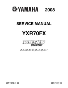
2008 Yamaha YXR70FX Rhino 700 Service Manual
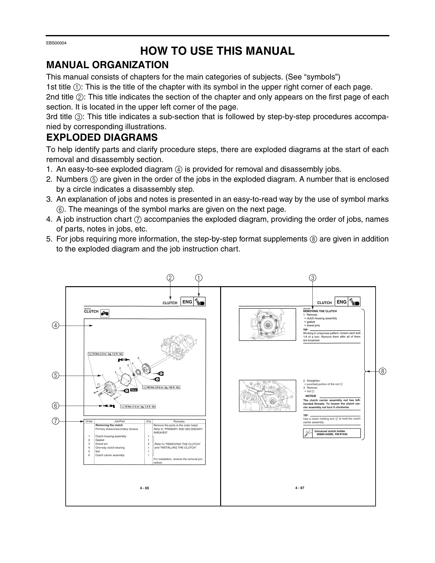
This is the full Yamaha service manual for the 2008 YXR70FX Rhino 700, issued under document number LIT-11616-21-58 as a first edition dated September 2007. It runs 497 pages and covers the 686 cc liquid-cooled, four-stroke SOHC single-cylinder machine across model codes 5B41, 5B45, 5B48, 5B49, 5B4B and 5B4E. Every chapter is laid out the way a Yamaha technician expects: exploded diagrams first, a job instruction chart, then step-by-step procedures with the special tools, torque values and service limits called out inline. If you own a Rhino 700 and intend to do your own maintenance, rebuilds or diagnostics, this is the document the dealer bay uses.
File Details
- Manual type: Service Manual
- Brand: Yamaha
- Model: YXR70FX Rhino 700
- Model codes: 5B41, 5B45, 5B48, 5B49, 5B4B, 5B4E
- Language: English
- Page count: 497
- File format: PDF
- Document number: LIT-11616-21-58
- Edition: First edition, September 2007
Chapters Covered
- General Information
- Specifications
- Periodic Checks and Adjustments
- Engine
- Cooling System
- Fuel Injection System
- Drive Train
- Chassis
- Electrical
- Troubleshooting
General Information
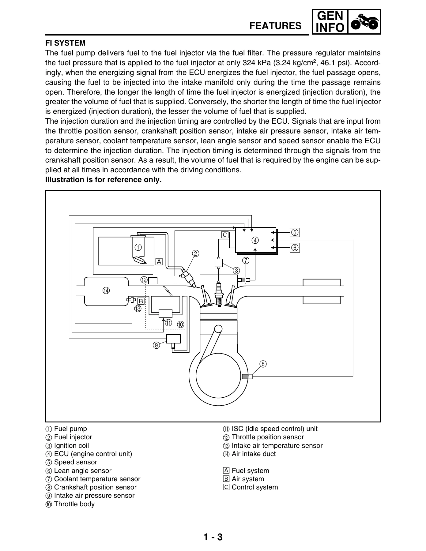
Vehicle identification numbers, the model label location, and the outline of the electronically controlled fuel injection system with a labelled component map of the machine. Instrument functions are documented here too: the multi-function meter, odometer and tripmeter switching, clock and hour meter settings, voltage display, fuel meter, and the self-diagnosis error code readout. General repair practice is covered — preparation for removal and disassembly, replacement parts policy, gasket and oil seal handling, lock washers and cotter pins, bearing and oil seal installation, circlip orientation, and electrical connector inspection. The special tools list is printed with part numbers for both the US/CDN YM/YU/YS/YK/ACC numbering and the 90890- international format.
Specifications
General machine dimensions, weight, engine type, bore and stroke, compression ratio and pressure, oil and coolant quantities, fuel tank capacity, spark plug type and gap, clutch and transmission data, chassis geometry, front and rear suspension stroke and spring rates, wheel and rim sizes, brake disc dimensions, and full electrical specifications. Engine service limits are tabulated here: cylinder bore, camshaft lobe dimensions, valve stem to guide clearance, valve spring free length and tilt, piston ring end gap and side clearance, crankshaft runout, big end side and radial clearance, clutch shoe thickness, V-belt width, and transmission shaft runout limits. Engine and chassis tightening torques are listed in dedicated tables, and the conversion table plus general tightening torque chart round out the section.
Periodic Checks and Adjustments
The emission control and general maintenance charts tell you what to inspect at each interval. Individual procedures cover valve clearance adjustment on a cold engine at TDC, throttle cable free play, spark plug inspection and gap, ignition timing with a timing light, compression pressure measurement, engine oil level and oil changes including the filter cartridge, air filter element cleaning and oiling, throttle body joint, fuel hose and breather hose checks, coolant level and coolant change with the air bleed sequence, V-belt inspection and replacement, and spark arrester cleaning. Chassis side covers brake pedal free play, parking brake adjustment, brake fluid level, front, rear and parking brake pad wear, brake hose and pipe inspection, hydraulic brake bleeding, select lever shift rod adjustment, brake light switch timing, final gear and differential gear oil level and changes, CV joint dust boots, steering system play, toe-in adjustment, front and rear shock absorber setup, tire and wheel inspection, and cable lubrication. The electrical section covers battery charging with both variable-current and constant-voltage methods, fuse checking with the amperage table, headlight beam adjustment, and headlight and tail/brake bulb replacement.
Engine
Engine removal starts with the V-belt cooling ducts, muffler and exhaust pipes, shift arm, hoses and leads, and the mounting bolts, with the reinstall torque sequence given in full. The cylinder head chapter walks through rocker arm and camshaft removal, decompressor inspection, valve and valve spring service with lapping and seat width measurement, and the tightening sequence and torques for the cylinder head bolts. Cylinder and piston work covers piston pin removal, cylinder bore measurement, piston ring side clearance and end gap, and ring end gap offsetting on assembly. The AC magneto chapter covers stator coil and crankshaft position sensor checking, starter clutch and torque limiter inspection, and rotor installation with the woodruff key. Balancer gears and oil pump gears, primary and secondary sheave disassembly with the sheave spring compressor, clutch inspection including one-way clutch operation and clutch shoe thickness, crankcase separation and reassembly, crankshaft and oil pump service, transmission and shift fork inspection, and the middle gear with shim selection formulas for both drive and driven pinion gears and gear lash measurement.
Cooling System
Radiator and coolant reservoir removal with the fan motor coupler and breather hose routing, radiator fin cleaning, radiator cap opening pressure testing with the pressure tester, thermostat testing in heated water and installation with the breather hole facing up, water pump disassembly and seal and bearing replacement with installed depths, and oil cooler inspection. Coolant flow and oil flow diagrams are included to show you exactly where each hose and pipe runs.
Fuel Injection System
The full FI circuit diagram, ECU self-diagnostic function, and the self-diagnostic function table listing every fault code and what the machine can and cannot do while that code is active. Diagnostic mode entry is documented, along with the diagnostic code table, sensor operation table, and actuator operation table. Troubleshooting details break down each fault code individually with the order of checks, wire colours and connector names. Separate procedures cover checking the intake air pressure sensor, intake air temperature sensor, fuel injector, throttle body, throttle position sensor adjustment, fuel pump and pressure regulator operation, fuel tank and fuel pump removal, air filter case and air intake duct installation, and the rollover valve.
Drive Train
Troubleshooting noises and the troubleshooting chart come first, then front constant velocity joints, differential gear and drive shaft service including universal joint disassembly, differential gear assembly removal, gear lash measurement with the gear lash tool, and shim adjustment. Rear constant velocity joints, final drive gear and drive shaft service covers final gear case disassembly, roller bearing removal and installation with a 150 °C housing heat, final drive pinion gear and ring gear positioning with shim thickness formulas, ring gear stopper adjustment, and final gear lash measurement and adjustment using ring gear shims and thrust washers.
Chassis
Seats, enclosure, hood and cargo bed removal, including gas spring removal and cargo bed disassembly. Steering wheel removal and installation, side door and panel removal with the quick fastener procedure, skid plate installation, enclosure frame and seat belt torque sequence, front and rear wheels with axle nut staking, brake disc and wheel hub inspection, front and rear brake pads, brake master cylinder disassembly with primary and secondary kits, front and rear brake calipers, parking brake pads, cable and disc, pedal assembly, steering shaft and steering assembly with rack and pinion backlash adjustment, tie-rod and steering knuckle, ball joint removal and installation with the ball joint remover set, front arms and front shock absorbers with spring preload and damping adjustment, rear knuckle and stabilizer, and rear arms and rear shock absorber. Gas-oil damper shock absorber handling and disposal procedures are also covered.
Electrical
Component locations, switch continuity checking with the switch illustration format, bulb and bulb socket checking, ignition system with circuit diagram and troubleshooting flow, electric starting system with starting circuit operation and the starter relay and load control relay checks, starter motor disassembly and commutator and brush measurement, charging system with stator coil resistance and charging voltage, lighting system, signaling system including brake light, neutral, high and low range, reverse, park, differential lock and four-wheel-drive indicator lights, coolant temperature warning light and fuel meter checks, speedometer check, cooling system circuit, fuel pump system, and the 2WD/4WD selecting system with the four-wheel-drive motor relay checks and differential gear motor test.
Troubleshooting
The final chapter breaks down starting failure and hard starting across the fuel, electrical and compression systems, poor idle speed performance, poor medium and high-speed performance, faulty drive train symptoms with their possible causes, faulty gear shifting including hard shifting and jumping out of gear, clutch performance problems, overheating and overcooling, faulty brake, shock absorber malfunction, unstable handling, and lighting system faults.
Why This Manual Belongs in Your Shop
The 2008 Yamaha YXR70FX Rhino 700 is a machine that earns its keep — hauling, towing and working in conditions that wear parts faster than any owner’s manual ever admits. When something lets go, the difference between a clean repair and a second teardown is having the right procedure, the right torque value and the right clearance limit in front of you. This service manual gives you all three, chapter by chapter, in the same order a Yamaha technician works.
Valve clearance, camshaft lobe dimensions, crankshaft runout, piston-to-cylinder clearance, V-belt wear limit, gear lash ranges, shock spring preload and rebound click counts, brake disc thickness, battery charging voltages, FI fault code diagnostics — every measurement you need is printed with its limit so you can decide replace or reuse without guessing. The exploded diagrams show how assemblies come apart and go back together, and the job instruction charts keep the order straight so nothing gets left on the bench.
IMAGES PREVIEW
Because the whole 497-page document arrives as an instant PDF download, there is no shipping wait and no binder to lose. Pull it up on a laptop or tablet in the garage, print the pages for the job you are doing, and keep the rest on file. One purchase covers the entire machine — engine, fuel injection, cooling, drive train, chassis and electrical — for as long as you own the Rhino.
Reviews
There are no reviews yet.