★ TRUSTED BY 321,897+ PROFESSIONALS WORLDWIDE
🏒
Trusted Business
Verified & Licensed
πŸ›‘οΈ
Virus Free Files
100% Safe Downloads
πŸ”’
Secure Payment
SSL Protected
⚑
Instant Delivery
Available Immediately
Sale!

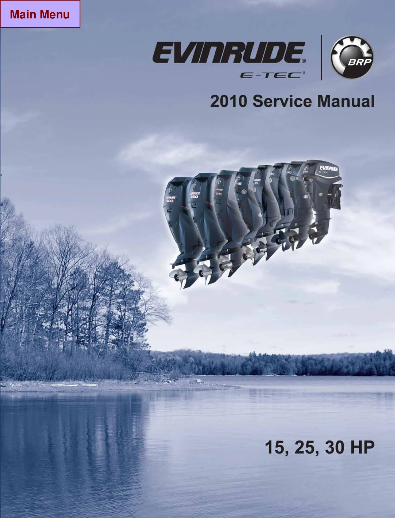
2010 Evinrude E-TEC 15 25 30 HP Service Manual – 2-Cylinder Outboard Repair PDF

Original price was: $34.95.Current price is: $19.95.

Complete 2010 service manual for 35.1 cu. in. (0.57 L) two-cylinder Evinrude E-TEC 15, 25 and 30 HP outboards. Covers the EMM, electrical and ignition, fuel, oiling, cooling, powerhead, midsection, gearcase, trim and tilt and manual starter, with torque specs, service charts, diagnostics and diagrams.

⚑
Instant PDF Download
Available immediately
πŸ’Ύ
Save to Your Device
Download & keep forever
πŸ›‘οΈ
Antivirus Scanned
100% virus-free
🌍
Trusted Worldwide
175,000+ customers

Description

File Details

  • Manual type: Service manual (workshop, repair and maintenance)
  • Brand: Evinrude / Johnson (BRP US Inc.)
  • Model year: 2010
  • Covered models: 15, 25 and 30 HP two-cylinder Evinrude E-TEC outboards, 35.1 cu. in. (0.57 L)
  • Language: English
  • File format: PDF
  • Page count: 372 pages
  • Published by: BRP US Inc. Technical Publications, 250 Sea Horse Drive, Waukegan, Illinois 60085, United States

What This 2010 Evinrude E-TEC 15 25 30 HP Service Manual Gives You

Evinrude E-TEC two-cylinder outboards do not have a carburetor, a distributor or a mechanical oil pump drive. They have an Engine Management Module that runs the alternator, the fuel and ignition timing, the injectors, the oil injection pump, the electric fuel pump and the idle speed, and that reports its own faults through LED indicators and a diagnostic connector. Servicing one without the correct reference is guesswork. This 2010 Evinrude E-TEC 15 25 30 HP service manual is the organized guide to that entire system, written for technicians who already understand outboard work and need the exact procedure, value and sequence.

The manual opens with the safety information, the abbreviations used throughout, the emission-related installation instructions and the model designation breakdown, then moves straight into the service specifications and standard torque specifications that everything else in the book references. From there it works through the outboard in the same order you would physically strip it: cover service, the EMM, system analysis and diagnostics, electrical and ignition, fuel, oiling, cooling, powerhead, midsection, gearcase, trim and tilt, and the manual starter.

Chapters Covered

  • Introduction – safety information, signal words, abbreviations and units of measurement, emission-related installation instructions, model and serial number locations, models covered in the manual, service specifications, standard torque specifications, product reference and nautical orientation
  • Special Tools – diagnostic tools, universal tools, electrical and ignition tools, fuel and oil system tools, powerhead tools, gearcase tools and shop aids
  • Installation and Predelivery – boat rigging, remote controls, information display systems, battery installation, fuel system requirements, cable and hose installation, Oetiker clamp servicing, outboard installation, hull preparation, transom measuring and drilling, drilling and hardware diagrams, lifting the outboard, steering systems, outboard mounting and rigging, control cable installation, SystemCheck harness connections, fuel and oil priming, before start-up, running checks, propellers, water test and final adjustments, trim sending unit and trim tab adjustment
  • Maintenance – inspection and maintenance schedule, anti-corrosion protection, sacrificial anodes and continuity testing, metallic component protection, exterior finishes, cooling system and flushing, water intake screens, lubrication of the steering system, tiller handle, swivel and trailering bracket, tilt tube, throttle and shift linkage, propeller shaft, gearcase lubricant, trim and tilt, battery and battery connections, fuel and oil systems, fuel filter, oil filters and reservoir, air silencer, hoses and connections, spark plugs and indexing, storage, pre-season service and submerged engines
  • Engine Cover Service – upper cover latch hook installation and lower cover removal and installation
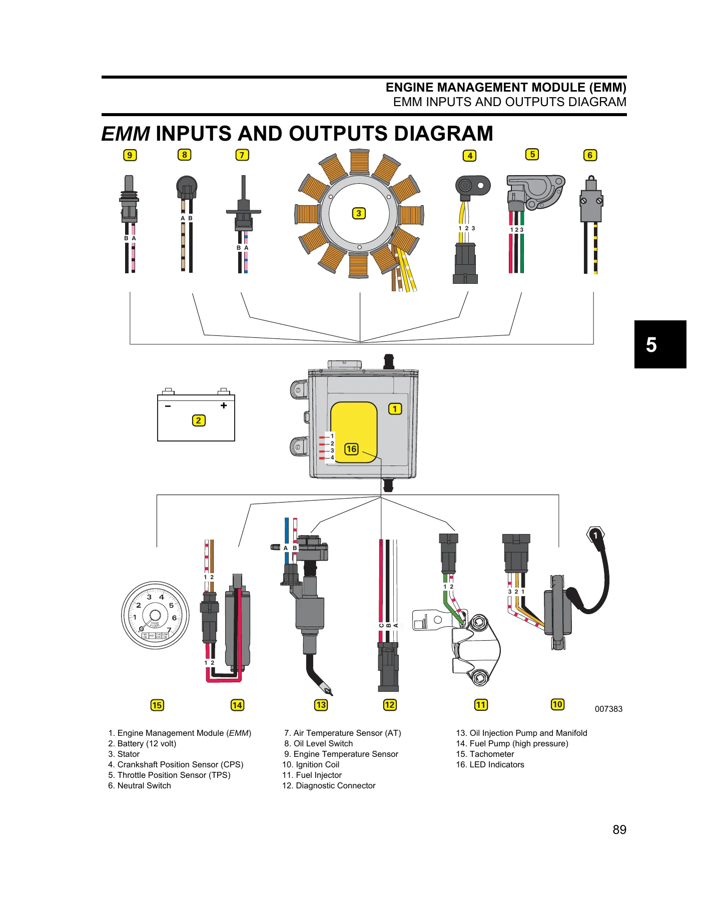
  • Engine Management Module (EMM) – description, EMM functions, EMM connections, LED indicators, EMM inputs and outputs diagram, internal sensors (EMM temperature, 55 V, 12 V and 5 V circuit sensors), external sensors (barometric pressure, air temperature, engine temperature, low oil switch, throttle position sensor, crankshaft position sensor, neutral switch), internal EMM functions, engine monitor system, S.A.F.E. warning system, shutdown mode, diagnostic software functions, static and dynamic tests, oil control settings, tiller/remote programming, ignition timing, TPS calibration, fuel injector servicing, reports, software replacement, EMM transfer and EMM servicing
  • System Analysis – visual and operational inspections, troubleshooting, dynamic tests and cylinder drop tests, fuel control adjustment, inductive amp meter test, EMM LED indicators, ignition output tests, crankshaft position sensor test, system voltage test, static and running ignition tests, ignition control circuit tests, ignition coil tests and fuel delivery tests
  • Electrical and Ignition – electrical harness connections and EMM J1-A pinout, ground circuits, fuse, sensor tests, stator tests and stator voltage output test, charging system tests, 55 V alternator circuit, start circuit operation, electric start tests, remote control switch tests, tilt/trim relay test, SystemCheck circuit tests, tachometer circuit tests, flywheel and stator servicing, ignition coil servicing, timing adjustments and TPS calibration, electric starter servicing and connector servicing
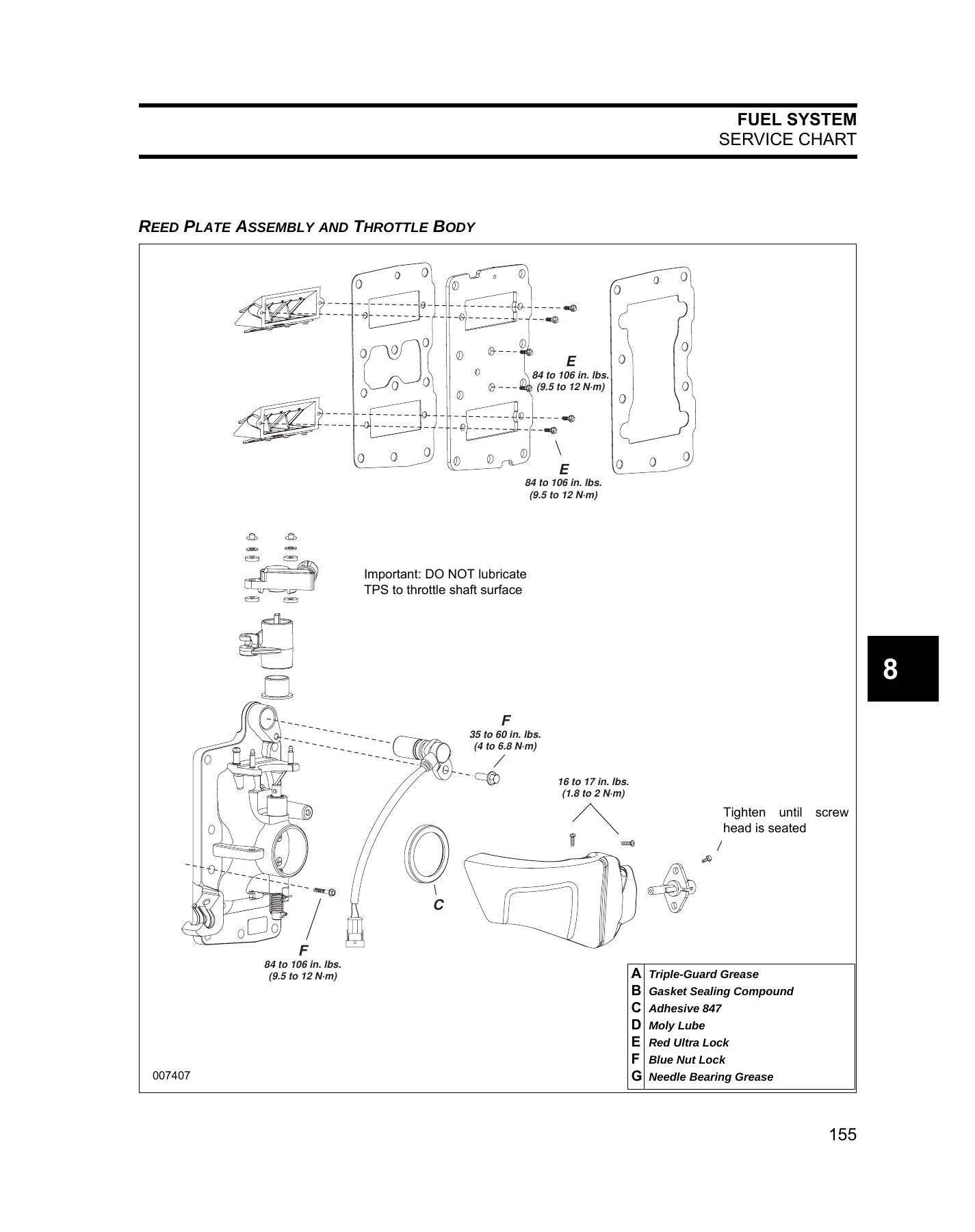
  • Fuel System – service chart, fuel system hose routing and circuit diagram, fuel lift pump, fuel filter, vapor separator, fuel circulation pump, fuel manifold, fuel injectors, fuel system pressure test, vapor separator vent check, fuel injector pressure and resistance tests, circulation pump resistance test, lift pump pressure, vacuum and diaphragm tests, anti-siphon valve test, relieving fuel system pressure, fuel filter and lift pump service, vapor separator and fuel injector service and intake manifold service
  • Oiling System – components, oil tank assembly, oil injection pump, electrical circuit, LOW OIL and NO OIL warning systems, cylinder and crankcase oil distribution, oil recirculation system, oil control settings, oil injection pump static test, voltage test, circuit resistance test and function test, oil injection fittings flow test, LOW OIL sending unit test and oil component servicing
  • Cooling System – components, water pump and intakes, exhaust housing, pressure relief valve, thermostat, operation, cylinder block and cylinder head cooling, vapor separator / EMM / battery charge module cooling, engine temperature check by software and pyrometer, idle operating temperature troubleshooting, temperature sender servicing and thermostat and pressure relief valve servicing
  • Powerhead – service chart, powerhead removal, disassembly, systems removal, throttle linkage removal, shift linkage removal, cylinder head removal, crankcase disassembly, crankshaft assembly removal, connecting rods and pistons, cylinder block cleaning, powerhead inspection, cylinder head, bearings, cylinder bore, pistons and piston rings, powerhead assembly, crankshaft assembly, pistons and connecting rods, crankcase assembly, cylinder head installation, megaphone and inner exhaust housing installation, shift and throttle linkage installation, final powerhead assembly, powerhead installation and shift linkage adjustment
  • Midsection – service chart, clamp screw service, exhaust housing service and removal/installation, mount service, exhaust relief muffler, stern bracket disassembly and assembly for power tilt and manual tilt models, trim sending unit removal and installation, tiller handle service, midsection and tiller adjustments
  • Gearcase – service chart, propeller service and inspection, gearcase leak test, trim tab service, gearcase removal and installation, water pump service, gearcase disassembly and pre-disassembly inspection, propeller shaft bearing housing removal, shifter/gear/propshaft removal, bearing and seal removal, seal and bearing installation and gearcase assembly
  • Trim and Tilt – service chart, system description, manual adjustment, trailering bracket and tilt support, routine inspections, troubleshooting, electrical circuit tests, relay testing, trim and tilt motor current draw and no load tests, trim gauge test, trim sender test and trim and tilt service
  • Manual Starter – service chart, recoil starter removal and installation, disassembly, cleaning and inspection and assembly
  • Safety – marine products and the safety of people who use them, outboard shift systems, speed control systems, steering control systems, fuel and electrical system safety, mounting system safety, hydraulic tilt/trim shock absorption, emergency stop system safety and a safety awareness test
  • Index, Trouble Check Chart and Diagrams – full alphabetical index, trouble check chart for no-start, hard start, stalling, low maximum RPM, excessive smoking, surging and rough running conditions, hose routing and water flow diagram, MWS instrument wiring harness, key switch and neutral safety switch diagrams, tiller harness and the Evinrude 15-30 HP EMM service code chart

Complete PDF Bookmark Tree

Complete Bookmarks

The complete bookmarks in the β€œ2010 Evinrude E-TEC 15 25 30 HP Service Manual – 2-Cylinder Outboard Repair PDF” are as follows:

INTRODUCTIONp. 5
ABBREVIATIONS USED IN THIS MANUALp. 8
Units of Measurementp. 8
List of Abbreviationsp. 8
EMISSION-RELATED INSTALLATION INSTRUCTIONSp. 9
Manufacturer’s Responsibilityp. 9
Dealer’s Responsibilityp. 9
Owner’s Responsibilityp. 9
EPA Emission Regulationsp. 9
MODEL DESIGNATIONp. 10
MODELS COVERED IN THIS MANUALp. 11
SERVICE SPECIFICATIONSp. 12
STANDARD TORQUE SPECIFICATIONSp. 14
PRODUCT REFERENCE AND ILLUSTRATIONSp. 14
SPECIAL TOOLSp. 15
DIAGNOSTIC TOOLSp. 16
UNIVERSAL TOOLSp. 16
ELECTRICAL / IGNITION TOOLSp. 18
FUEL /OIL SYSTEM TOOLSp. 19
POWERHEAD TOOLSp. 19
GEARCASE TOOLSp. 20
SHOP AIDSp. 22
INSTALLATION AND PREDELIVERYp. 25
BOAT RIGGINGp. 26
Remote Controlsp. 26
Information Display Systemsp. 28
Battery Installationp. 30
Auxiliary Battery Chargingp. 32
Battery and Switch Wiring Diagramsp. 33
Fuel System Requirementsp. 34
Cable and Hose Installationp. 36
Oetiker Clamp Servicingp. 38
OUTBOARD INSTALLATIONp. 40
Hull Preparationp. 40
Transom Measuring and Drillingp. 41
Drilling and Hardware Diagramsp. 44
Lifting the Outboardp. 50
Steering Systemsp. 51
Outboard Mountingp. 52
OUTBOARD RIGGINGp. 54
Common Practices – All Modelsp. 54
Cable, Hose, and Wire Routingp. 55
Control Cable Installationp. 55
SystemCheck Harness Connectionsp. 57
FUEL AND OIL PRIMINGp. 58
Fuel Requirementsp. 58
Fuel System Primingp. 59
Oil Requirementsp. 59
Oil Injection Ratep. 59
Break-In Oilingp. 61
Oil Supply Primingp. 61
BEFORE START-UPp. 62
Gearcase Lubricantp. 62
Oil Levelp. 62
Trim and Tilt Fluidp. 62
RUNNING CHECKSp. 63
Engine Monitoring Systemp. 63
Fuel Systemp. 63
Emergency Stop / Key Switchp. 63
Remote Control Operationp. 63
Start-In-Gear Preventionp. 63
Tachometer Pulse Settingp. 63
Water Pump Overboard Indicatorp. 64
Operating Temperaturep. 64
Idle Speedp. 64
Break-Inp. 64
PROPELLERSp. 65
Propeller Selectionp. 65
Propeller Hardware Installationp. 65
WATER TEST AND FINAL ADJUSTMENTSp. 66
Engine Mounting Height Adjustmentp. 66
Trim Sending Unit Adjustmentp. 67
Trim Tab Adjustmentp. 68
MAINTENANCEp. 69
INSPECTION AND MAINTENANCE SCHEDULEp. 70
ANTI-CORROSION PROTECTIONp. 71
Sacrificial Anodesp. 71
Testing Procedure – Continuityp. 71
Metallic Component Protectionp. 71
Exterior Finishesp. 71
COOLING SYSTEMp. 72
Flushingp. 72
Water Intake Screensp. 73
Additional Maintenancep. 73
LUBRICATIONp. 73
Steering Systemp. 73
Tiller Handlep. 73
Swivel Bracket and Trailering Bracketp. 74
Tilt Tubep. 74
Throttle and Shift Linkagep. 74
Propeller Shaftp. 75
Gearcase Lubricantp. 75
Trim and Tiltp. 76
BATTERY AND BATTERY CONNECTIONSp. 77
FUEL AND OIL SYSTEMSp. 78
Fuel Filterp. 78
Oil Filters and Oil Reservoirp. 78
Air Silencerp. 78
Hoses and Connectionsp. 78
SPARK PLUGSp. 79
Indexingp. 79
STORAGEp. 80
Fuel System Treatmentp. 80
Internal Engine Treatmentp. 80
Additional Recommendationsp. 81
PRE-SEASON SERVICEp. 81
Outboard Mounting Boltsp. 81
Gearcase Lubricantp. 81
Battery(s)p. 81
Power Trim and Tiltp. 81
Operational Checksp. 81
SUBMERGED ENGINESp. 82
Engine Dropped Overboard (Not Running)p. 82
Engine Dropped Overboard (Running)p. 82
Engine Dropped Overboard (In Salt Water)p. 82
Prolonged Submersion (Fresh or Salt Water)p. 82
ENGINE COVER SERVICEp. 83
UPPER COVER SERVICEp. 84
Latch Hook Installationp. 84
LOWER COVER SERVICEp. 85
Lower Cover Removalp. 85
Lower Cover Installationp. 85
Latch Handle Installationp. 87
NOTESp. 88
Technician’s Notesp. 88
Related Documentsp. 88
ENGINE MANAGEMENT MODULE (EMM)p. 89
DESCRIPTIONp. 90
EMM Functionsp. 90
EMM Connectionsp. 90
LED Indicatorsp. 90
EMM INPUTS AND OUTPUTS DIAGRAMp. 91
INTERNAL SENSORSp. 92
EMM Temperature Sensorp. 92
55 V Circuit Sensorp. 92
12 V Circuit Sensorp. 92
5 V Circuit Sensorp. 92
Barometric Pressure Sensorp. 93
EXTERNAL SENSORSp. 93
Air Temperature Sensorp. 93
Engine Temperature Sensorp. 94
Low Oil Switchp. 94
Throttle Position Sensorp. 95
Crankshaft Position Sensorp. 95
Neutral Switchp. 95
INTERNAL EMM FUNCTIONSp. 96
ROM Verificationp. 96
Idle Controllerp. 96
RPM Limiterp. 96
Neutral RPM Limiterp. 96
Engine Monitor and Warning Systemsp. 96
Fault Code Creation and Storagep. 96
ENGINE MONITOR SYSTEMp. 96
System Self-Testp. 97
Service Modep. 97
Engine Runningp. 97
S.A.F.E. WARNING SYSTEMp. 97
Activationp. 97
Recoveryp. 97
SHUTDOWN MODEp. 98
Recoveryp. 98
DIAGNOSTIC SOFTWARE FUNCTIONSp. 98
Communicationp. 98
Static Informationp. 99
Dynamic Informationp. 100
Stored Service Codes (Faults)p. 100
Hard Faultsp. 100
Persistent Faultsp. 100
Static Testsp. 100
Dynamic Testsp. 101
Oil Control Settingsp. 102
Tiller/Remote Programmingp. 102
Ignition Timingp. 103
TPS Calibrationp. 103
Fuel Injector Servicingp. 104
Reportsp. 104
Software Replacementp. 105
EMM Transferp. 105
EMM SERVICINGp. 106
Removalp. 106
Installationp. 106
SYSTEM ANALYSISp. 107
DIAGNOSTIC PROCEDURESp. 108
Visual Inspectionsp. 108
Operational Inspectionsp. 108
Troubleshootingp. 109
DYNAMIC TESTSp. 110
Cylinder Drop Testsp. 110
Fuel Control Adjustmentp. 110
Inductive Amp Meter Testp. 110
EMM LED INDICATORSp. 111
Key ONp. 111
Startingp. 111
Runningp. 112
IGNITION OUTPUT TESTSp. 113
Required Ignition Systemsp. 113
Wiring Inspectionp. 113
Crankshaft Position Sensor (CPS) Testp. 114
System Voltage Testp. 114
Static Ignition Testp. 115
Running Ignition Testsp. 116
Ignition Control Circuit Testsp. 117
Ignition Coil Testsp. 117
FUEL DELIVERY TESTSp. 118
Fuel Pump Static Testp. 118
Fuel Injector Static Testp. 118
Running Fuel System Testsp. 119
NOTESp. 120
Technician’s Notesp. 120
Related Documentsp. 120
ELECTRICAL AND IGNITIONp. 121
SERVICE CHARTp. 122
IGNITION SYSTEM CIRCUIT DIAGRAMp. 124
ELECTRICAL HARNESS CONNECTIONSp. 125
Engine Harness to Stator Connectorp. 125
EMM J1-A Connectorp. 125
GROUND CIRCUITSp. 126
EMM Ground Testsp. 126
Additional Ground Testsp. 126
FUSEp. 126
SENSOR TESTSp. 127
Crankshaft Position Sensor (CPS) Testp. 127
Throttle Position Sensor (TPS) Testp. 127
Engine Temperature Sensor Testp. 128
Air Temperature Sensor (AT) Testp. 128
STATOR TESTSp. 129
Stator Resistance Testsp. 129
Stator Voltage Output Testp. 129
CHARGING SYSTEM TESTSp. 131
Charging System Circuit Diagramp. 131
12 V Charging Circuitp. 132
55 V Alternator Circuitp. 133
ELECTRIC START CIRCUITp. 134
Start Circuit Diagramp. 134
Start Circuit Operationp. 135
ELECTRIC START TESTSp. 136
Starter Solenoid Testp. 136
No Load Current Draw Testp. 137
REMOTE CONTROL SWITCH TESTSp. 138
Key Switch Testp. 138
Neutral Start Circuit Testp. 138
Neutral Start Switch Testp. 139
Emergency Stop Switch Testp. 139
TILT/TRIM RELAY TESTp. 140
Operationp. 140
Test Procedurep. 140
SystemCheck CIRCUIT TESTSp. 141
Gauge Self-Test Checkp. 141
LOW OIL Circuit Testp. 142
TACHOMETER CIRCUIT TESTSp. 143
FLYWHEEL AND STATOR SERVICINGp. 143
Flywheel Removalp. 143
Stator Servicep. 144
Flywheel Installationp. 144
IGNITION COIL SERVICINGp. 145
Ignition Coil Removalp. 145
Ignition Coil Installationp. 145
TIMING ADJUSTMENTSp. 146
Timing Pointerp. 146
Timing Verificationp. 146
TPS Calibrationp. 146
ELECTRIC STARTER SERVICINGp. 147
Starter Removalp. 147
Starter Disassemblyp. 147
Starter Cleaning and Inspectionp. 148
Starter Assemblyp. 149
Starter Installationp. 151
CONNECTOR SERVICINGp. 151
DEUTSCH Connectorsp. 151
AMP Connectorsp. 152
Packard Connectorsp. 154
FUEL SYSTEMp. 155
SERVICE CHARTp. 156
FUEL SYSTEM HOSE ROUTINGp. 158
FUEL SYSTEM CIRCUIT DIAGRAMp. 159
COMPONENTSp. 160
Fuel Lift Pumpp. 160
Fuel Filterp. 160
Vapor Separatorp. 160
Fuel Circulation Pumpp. 161
Fuel Manifoldp. 162
Fuel Injectorsp. 162
FUEL SYSTEM TESTSp. 163
Fuel System Pressure Testp. 163
Vapor Separator Vent Checkp. 164
Fuel Injector Pressure Testp. 164
Fuel Injector Resistance Testp. 164
Circulation Pump Resistance Testp. 165
Lift Pump Pressure Testp. 165
Lift Pump Vacuum Testp. 166
Lift Pump Diaphragm Testp. 166
Anti-Siphon Valve Testp. 167
FUEL COMPONENT SERVICINGp. 168
Relieving Fuel System Pressurep. 168
Fuel Filter Servicep. 169
Fuel Lift Pump Servicep. 169
Vapor Separator and Fuel Injector Servicep. 170
Intake Manifold Servicep. 175
NOTESp. 178
Technician’s Notesp. 178
Related Documentsp. 178
OILING SYSTEMp. 179
SERVICE CHARTp. 180
OIL SUPPLY DIAGRAMSp. 181
OIL RECIRCULATION DIAGRAMp. 182
OILING SYSTEM CIRCUIT DIAGRAMp. 183
COMPONENTSp. 184
Oil Tank Assemblyp. 184
Oil Injection Pumpp. 184
Electrical Circuit (55 V)p. 184
LOW OIL Warningp. 185
NO OIL Warningp. 185
Cylinder and Crankcasep. 185
Oil Recirculation Systemp. 186
OIL CONTROL SETTINGSp. 186
Oil Primingp. 186
Oiling Ratesp. 186
Break-in Oilingp. 186
OILING SYSTEM TESTSp. 187
Oil Injection Pump Static Testp. 187
Oil Injection Pump Voltage Testp. 187
Oil Injection Pump Circuit Resistance Testp. 188
Oil Injection Pump Function Testp. 188
Oil Injection Fittings Flow Testp. 189
LOW OIL Sending Unit Testp. 189
OIL COMPONENT SERVICINGp. 190
Oil Distribution Hosesp. 190
Oil Tank Assemblyp. 191
Oil Injection Pumpp. 192
COOLING SYSTEMp. 193
HOSE ROUTING AND WATER FLOW DIAGRAMSp. 194
COMPONENTSp. 195
Water Pump and Intakesp. 195
Exhaust Housingp. 195
Pressure Relief Valvep. 196
Thermostatp. 196
OPERATIONp. 197
Cylinder Block / Cylinder Head Coolingp. 197
Vapor Separator, EMM and Battery Charge Module Coolingp. 197
ENGINE TEMPERATURE CHECKp. 198
Software Methodp. 198
Pyrometer Methodp. 198
Idle Operating Temperature Troubleshooting (Below Range)p. 199
TEMPERATURE SENDER SERVICINGp. 200
Removalp. 200
Installationp. 200
THERMOSTAT AND PRESSURE RELIEF VALVE SERVICINGp. 200
Disassemblyp. 200
Inspectionp. 201
Assemblyp. 201
NOTESp. 202
Technician’s Notesp. 202
Related Documentsp. 202
POWERHEADp. 203
SERVICE CHARTp. 204
POWERHEAD REMOVALp. 206
POWERHEAD DISASSEMBLYp. 208
Systems Removalp. 208
Throttle Linkage Removalp. 208
Shift Linkage Removalp. 208
Cylinder Head Removalp. 209
Crankcase Disassemblyp. 209
Crankshaft Assembly Removalp. 209
Connecting Rods and Pistonsp. 210
Crankshaftp. 210
CYLINDER BLOCK CLEANINGp. 212
POWERHEAD INSPECTIONp. 213
Cylinder Headp. 213
Bearingsp. 213
Cylinder Borep. 214
Pistonsp. 214
Piston Ringsp. 214
POWERHEAD ASSEMBLYp. 215
Crankshaft Assemblyp. 215
Pistons and Connecting Rodsp. 216
Crankshaft Assembly Installationp. 218
Crankcase Assemblyp. 218
Cylinder Head Installationp. 220
Megaphone and Inner Exhaust Housing Installationp. 220
Shift Linkage Installationp. 221
Throttle Linkage Installationp. 222
Final Powerhead Assemblyp. 223
POWERHEAD INSTALLATIONp. 223
Powerhead Mountingp. 223
Shift Linkage Adjustmentp. 225
Pre-Service Adjustmentsp. 225
POWERHEAD VIEWSp. 226
Port Electric Start Modelsp. 226
Starboard Electric Start Modelsp. 226
Port Rope Start Modelsp. 227
Starboard Rope Start Modelsp. 227
Frontp. 228
Rearp. 229
Topp. 230
MIDSECTIONp. 231
SERVICE CHARTp. 232
CLAMP SCREW SERVICEp. 236
EXHAUST HOUSING SERVICEp. 237
Exhaust Housing Removalp. 237
Exhaust Housing Installationp. 237
Mount Servicep. 238
Exhaust Relief Mufflerp. 240
STERN BRACKET – Power Tilt Modelsp. 241
Stern Bracket Disassembly (Power Tilt)p. 241
Stern Bracket Assembly (Power Tilt)p. 243
Trim Sending Unit Removalp. 247
Trim Sending Unit Installationp. 248
STERN BRACKET – Manual Tilt Modelsp. 249
Stern Bracket Disassembly (Manual Tilt)p. 249
Stern Bracket Assembly (Manual Tilt)p. 253
TILLER HANDLE SERVICEp. 259
Removalp. 259
Disassemblyp. 261
Inspectionp. 265
Assemblyp. 265
Installationp. 272
MIDSECTION AND TILLER ADJUSTMENTSp. 276
Throttle Friction Adjustmentp. 276
Steering Friction Adjustmentp. 276
Tiller Height Adjustmentp. 277
Tiller Handle Ratchetp. 277
Tiller Handle Frictionp. 277
NOTESp. 278
Technician’s Notesp. 278
Related Documentsp. 278
GEARCASEp. 279
SERVICE CHARTp. 280
PROPELLER SERVICEp. 281
Inspectionp. 281
GEARCASE LEAK TESTp. 281
TRIM TAB SERVICEp. 282
Removalp. 282
Installationp. 282
GEARCASE REMOVAL AND INSTALLATIONp. 282
Gearcase Removalp. 282
Gearcase Installationp. 283
WATER PUMP SERVICEp. 284
Disassemblyp. 284
Inspectionp. 285
Assemblyp. 285
GEARCASE DISASSEMBLYp. 287
Pre-Disassembly Inspectionp. 287
Propeller Shaft Bearing Housing Removalp. 288
Shifter, Gear and Propshaft Removalp. 289
BEARING AND SEAL REMOVALp. 291
Driveshaft Sealsp. 291
Driveshaft Bearingp. 291
Pinion Bearingsp. 291
Forward Bearingp. 291
Shift Rod Bushing and O-ringp. 292
Prop Shaft Bearing Housing Seals and O-ringp. 292
SEAL AND BEARING INSTALLATIONp. 293
Propeller Shaft Bearing Housing Bearingsp. 293
Propeller Shaft Bearing Housing Seals and O-ringp. 293
Shift Rod Bushing and O-ringp. 294
Forward Bearingp. 294
Pinion Bearingsp. 294
Driveshaft Bearingp. 295
Driveshaft Sealsp. 295
GEARCASE ASSEMBLYp. 296
Propshaft, Gear and Shifter Installationp. 296
Propeller Shaft Bearing Housing Installationp. 299
TRIM AND TILTp. 301
SERVICE CHARTp. 302
SYSTEM DESCRIPTIONp. 303
Manual Adjustmentp. 303
Trailering Bracket And Tilt Supportp. 303
ROUTINE INSPECTIONSp. 304
Generalp. 304
Reservoir Fluidp. 304
Manual Release Valvep. 304
Stern Bracketsp. 304
TROUBLESHOOTINGp. 304
ELECTRICAL CIRCUIT TESTSp. 305
Relay Testingp. 305
Trim and Tilt Motor Current Draw Testsp. 305
Trim and Tilt Motor No Load Testp. 306
Trim Gauge Testp. 306
Trim Sender Testp. 307
TRIM AND TILT SERVICEp. 307
Removalp. 307
Disassemblyp. 308
Assemblyp. 310
Installationp. 311
ADJUSTMENTSp. 312
MANUAL STARTERp. 313
SERVICE CHARTp. 314
RECOIL STARTER REMOVALp. 315
RECOIL STARTER INSTALLATIONp. 316
RECOIL STARTER DISASSEMBLYp. 317
RECOIL STARTER CLEANING AND INSPECTIONp. 319
RECOIL STARTER ASSEMBLYp. 320
SAFETYp. 323
TABLE OF CONTENTSp. 323
MARINE PRODUCTS AND THE SAFETY OF PEOPLE WHO USE THEMp. 325
Outboard Shift Systems and Safetyp. 326
Outboard Speed Control System and Safetyp. 327
Outboard Steering Control System and Safetyp. 328
Outboard Fuel, Electrical System, and Safetyp. 330
Outboard Mounting System and Safetyp. 333
If weakened, parts could fail later on the water, when not expectedp. 334
Outboard Hydraulic Tilt/Trim Shock Absorption System and Safetyp. 335
Outboard Emergency Stop System and Safetyp. 336
Summing upp. 338
MARINE PRODUCTS AND THE SAFETY OF PEOPLE WHO FIX THEMp. 339
Handling Outboardsp. 339
Handling Lead/Acid Batteriesp. 343
Gasoline – Handle With Care!p. 344
Hazardous Productsp. 345
Safety Awareness Testp. 346
INDEXp. 347
TROUBLE CHECK CHARTp. 355
OUTBOARD WILL NOT STARTp. 355
OUTBOARD WILL NOT STARTp. 356
OUTBOARD HARD TO STARTp. 357
OUTBOARD WILL NOT SHUT OFFp. 358
OUTBOARD STARTS AND STALLSp. 358
OUTBOARD STARTS, LOW MAXIMUM RPMp. 359
EXCESSIVE SMOKINGp. 359
OUTBOARD SURGES, RUNS ROUGHp. 360
DIAGRAMSp. 361
Return to Main Menu

Diagnostics, Service Codes and the EMM

A large part of this manual deals with the Engine Management Module, and that is where the 15, 25 and 30 HP E-TEC differs most from anything else in the shed. The book explains the internal sensors the EMM uses to monitor its own fuel injector driver temperature and its 55 V, 12 V and 5 V circuits, along with the external sensors it reads: barometric pressure, air temperature, cylinder head temperature, throttle position, crankshaft position and the low oil switch. Each one is described with the thresholds that trigger a reaction and the service code that gets stored.

The EMM LED indicators are covered in detail. The manual explains what each of the four LEDs means with the key on, during cranking and while running, so you can read the module before you ever connect a laptop. It then walks through the diagnostic software functions – static tests for ignition, fuel injectors, oil injector and fuel pump, dynamic tests for cylinder drop, oil control settings for TC-W3 or XD100, powerhead break-in, TPS calibration and ignition timing verification. The S.A.F.E. warning system and shutdown mode are both spelled out, including the conditions that put the outboard into reduced-speed operation and the conditions that stop it completely until a stored code is cleared.

Behind the electronics, the Evinrude 15 25 30 HP service manual keeps the mechanical side just as thorough. The fuel section deals with the lift pump, the in-line filter, the water-cooled vapor separator with its float-controlled vent and pressure regulator, the electric circulation pump and the injectors, with pressure tests, resistance tests and vacuum tests for each. The oiling section explains the 55 V electric oil injection pump, the manifold that distributes oil to the crankcase and cylinder block, the recirculation system, and the LOW OIL and NO OIL warning logic. The cooling section covers the water pump, exhaust housing, thermostat, pressure relief valve and the cooling circuits that feed the vapor separator, EMM and battery charge module.

Powerhead, Midsection and Gearcase Work

The powerhead chapter is a full rebuild guide. It starts with removal and disassembly, covers removing the systems, throttle linkage, shift linkage and cylinder head, then splits the crankcase and lifts the crankshaft out. From there it covers separating the connecting rods and pistons, cleaning the cylinder block, inspecting the cylinder head for warpage, checking the bearings, measuring the cylinder bore for out-of-round, taper and oversize, checking piston ring end gap, and then building the whole thing back up – crankshaft assembly, pistons and connecting rods, crankcase sealing with Gel-Seal II, cylinder head installation, megaphone and inner exhaust housing, shift and throttle linkage, final assembly and installation back onto the exhaust housing.

The midsection chapter handles clamp screws, the exhaust housing, upper and lower motor mounts, the exhaust relief muffler, the stern bracket for both power tilt and manual tilt models, the trim sending unit and the complete tiller handle – including the twist grip, helix halves, rollers, guides, throttle cable, shift cable, detent, start switch, stop switch and trim switch. Steering friction, throttle friction, tiller height and tiller handle ratchet adjustments are all included.

The gearcase chapter covers the propeller, the leak test, the trim tab, removal and installation, water pump service, full disassembly, bearing and seal removal, seal and bearing installation and reassembly of the propshaft, gears, clutch dog and shifter. A service chart at the front of the chapter collects the torque values for the whole assembly.

Specifications, Torque Values and Reference Data

Throughout the book, torque values are printed at the point of use, and the general specification tables cover the full throttle operating range, idle RPM in gear and in neutral, weights by model, lubrication requirements, engine type, displacement, bore and stroke, standard bore, crankshaft journal dimensions, rod crankpin, piston ring end gap, fuel pressure, fuel lift pump pressure, maximum fuel inlet vacuum, minimum octane, cooling system thermostat and maximum temperature, battery requirements, alternator output, tachometer setting, fuse rating, ignition type and firing order, RPM limits, spark plug specification and gap, gear ratio, gearcase lubricant and capacity, and trim and tilt fluid capacity and ranges. The standard torque specification table at the front covers fasteners by size in inch-pounds, foot-pounds and Newton-meters.

Who This Manual Is For

This is a professional-level reference. It assumes the reader is a qualified technician familiar with Evinrude and Johnson special tools, and it says so plainly. That makes it the right book for a marine mechanic, a dealer workshop, an experienced owner doing their own rebuild, or anyone maintaining a fleet of small two-cylinder E-TEC outboards. It is equally useful as a reference for the owner who wants to understand what their dealer is doing and why.

Get the 2010 Evinrude E-TEC 15 25 30 HP Service Manual

With this manual on hand you can pull fault codes and interpret them, run the static and dynamic tests, check the 55 V and 5 V circuits, test the stator and charging system, service the fuel and oiling systems, rebuild a powerhead to the correct clearances and torque values, recondition a gearcase, service the trim and tilt unit, and set the timing and TPS calibration correctly. Those are jobs where the wrong specification or the wrong sequence costs parts and time, and where a factory-issued service manual is the only thing that gives you the numbers with confidence.

IMAGES PREVIEW

2010 Evinrude E-TEC 15 25 30 HP Service Manual - 2-Cylinder Outboard Repair PDF β€” PDF page 1 preview
2010 Evinrude E-TEC 15 25 30 HP Service Manual - 2-Cylinder Outboard Repair PDF β€” PDF page 91 preview
2010 Evinrude E-TEC 15 25 30 HP Service Manual - 2-Cylinder Outboard Repair PDF β€” PDF page 157 preview

Delivery is instant. The file is a PDF download, there is no shipping and nothing to wait for, and it opens on a desktop, laptop, tablet or phone. Print the pages you need for the bench, keep the rest on the screen, and work through the job with the exact procedures, the exact torque figures and the exact service codes in front of you.
Reviews

There are no reviews yet.

Be the first to review “2010 Evinrude E-TEC 15 25 30 HP Service Manual – 2-Cylinder Outboard Repair PDF”

What Our Customers Say

β˜…β˜…β˜…β˜…β˜… Live reviews from customers
Loading customer reviews...
0
    0
    Your Cart
    Your cart is emptyReturn to Shop
    πŸ›’
    Recently Purchased
    πŸ•’ verified order