2012-2016 Mitsubishi Fuso Canter FE FG Series Truck Service Manual – PDF DOWNLOAD
Original price was: $86.95.$39.95Current price is: $39.95.
2012-2016 Mitsubishi Fuso Canter FE FG Series Truck Service Manual – PDF DOWNLOAD
Description
2012-2016 Mitsubishi Fuso Canter FE FG Series Truck Service Manual – PDF DOWNLOAD
DESCRIPTION:
2012-2016 Mitsubishi Fuso Canter FE FG Series Truck Service Manual – PDF DOWNLOAD
Publication Numbers:
00ELT0001 (2012)
00ELT0014 (2013)
00ELT0031 (2014)
00ELT0032 (2014 1/2)
00ELT0059 (2015-2016)
FOREWORD:
This Service Manual contains maintenance and repair methods for the Mitsubishi Fuso Truck FE. FG Series. Read this manual carefully as an aid in providing correct, efficient maintenance. Please note that the information and specifications contained within this manual may change without notice. This is due to product modifications and continued vehicle improvements that are made throughout the model years. Should you encounter any discrepancy in the information provided
TABLE OF CONTENTS:
2012-2016 Mitsubishi Fuso Canter FE FG Series Truck Service Manual – PDF DOWNLOAD
2012 to 2016 Canter Service Manual 1
Group Index 2
Modification Summary 3
Modification Summary (2013 Model Year) 4
Modification Summary (2014 Model Year) 7
Modification Summary (2014 1/2 Model Year) 9
Modification Summary (2015 to 2016 Model Years) 13
Group 00 – General 17
Group 00 – General (2012 Model Year) 18
Index 19
Equipment Type Codes List 20
Power Train Table 21
How To Read This Manual 22
Chassis Number, Engine Number, Power Train Label 30
Vehicle Identification Number 31
Precautions for Maintenance Operation 32
1 Handling Precautions for Electric Circuits 37
2 Service Precautions for Alternators 40
3 Intermittent Faults 42
4 Precautions for Arc Welding 43
5 Cautions When Handling DEF 44
6 Precautions When Repainting 44
7 Precautions When Handling a Vehicle with DUONIC System 44
8 Precautions on Cleaning When Servicing the Engine and Transmission 45
Jacking Up the Vehicle 48
Diagnosis Codes 52
1 Diagnosis Codes 52
2 Reading and Erasing the Diagnosis Code 58
Table of Standard Tightening Torques 62
Group 00 – General (2013 Model Year) 65
Index 66
Precautions for Maintenance Operation 67
Group 00 – General (2014 to 2014 1/2 Model Years) 69
Index 70
Equipment Type Codes List 71
Power Train Table 72
How to Read This Manual 73
Chassis Number, Engine Number, Power Train Label 81
Vehicle Identification Number 82
Precautions for Maintenance Operation 83
1 Handling Precatuions for Electric Circuits 88
2 Service Precautions for Alternators 91
3 Intermittent Faults 92
4 Precautions for Arc Welding 94
5 Cautions When Handling DEF 95
6 Precautions When Repainting 95
7 Precautions When Handling a Vehicle with DUONIC System 95
8 Precautions on Cleaning When Servicing the Engine and Transmission 96
Jacking Up the Vehicle 99
Diagnosis Codes 103
1 Diagnosis Codes 103
2 Reading and Erasing the Diagnosis Code 109
Table of Standard Tightening Torques 113
Group 00 – General (2015 to 2016 Model Years) 119
Index 120
Power Train Table 121
Vehicle Identification Number 122
Group 01 – Maintenance Schedule 123
Group 01 – Maintenance Schedule (2012 to 2014 1/2 Model Years) 124
Index 125
How To Read the Maintenance Schedule Tables 126
Maintenance Schedule Tables 128
Maintenance Operations 132
Lubrication Tables 134
Lubrication 136
Group 01 – Maintenance Schedule (2015 to 2016 Model Years) 140
Index 141
How to Read the Maintenance Schedule Tables 142
1 For Maintenance Schedule in Severe Use 143
2 Maintenance Schedule 143
Maintenance Schedule Tables 144
Lubrication Tables 150
Group 11 – Engine 152
Index 153
Specifications 154
Structure and Operation 155
1 Engine Proper 155
2 Timing System 155
3 Main Bearing 157
4 Connecting Rod, Piston 157
5 Rocker Arms, Tappets 160
Troubleshooting 161
Engine Removal and Installation 162
<Tilt Cab> 162
<Fixed Cab> 166
Work for Overhauling Engine 170
Timing Gear Case 200
Timing Gear, Chain 206
Overhead, Cylinder Head 220
Piston and Connecting Rod 240
Flywheel 250
Crankshaft and Crankcase 254
Group 12 – Lubrication 267
Index 268
Specifications 269
Structure and Operation 270
1 Lubrication System 270
2 Oil Pump/Vacuum Unit 271
3 Oil Filter 273
4 Oil Cooler 273
Troubleshooting 274
On-Vehicle Inspection and Adjustment 275
1 Oil Filter Replacement 275
2 Engine Oil Replacement 277
3 Inspection of Engine Oil Level 279
4 Inspection of Engine Oil Leaks 279
5 Oil Pressure Measurement 280
Oil Pan, Oil Strainer 281
Oil Pump/Vacuum Unit 285
Oil Filter, Oil Cooler 286
Group 13 – Fuel and Engine Control 289
Index 290
Specifications 292
Structure and Operation 293
1 High Pressure Electronic Injection System 293
Troubleshooting 301
On-Vehicle Inspection and Adjustment 303
1 Inspecting and Adjusting No-load Minimum and Maximum Speeds 303
2 Air-bleeding of Fuel System 304
3 Fuel Filter Replacement 304
4 Fuel Hose Replacement 307
Fuel Tank, Fuel Pump 309
<FE> 309
<FG> 311
Fuel Filter 313
Accelerator Pedal 317
High Pressure Fuel Pump 319
Common Rail, Injector 323
Group 13E – Common Rail System 327
Group 13E – Common Rail System (2012 to 2014 Model Years) 328
Index 329
Specifications 330
Structure and Operation 332
1 High Pressure Electronic Injection System 332
2 Engine Electronic Control System 334
Troubleshooting 350
1 Inspections Based on Diagnosis Codes 350
2 FUSO Diagnostics Service Data (Actual Values) 961
3 FUSO Diagnostics Actuator Test (Actuations) 977
4 Alteration and Reset of Coding Data in Engine Electronic Control Unit 979
5 Inspections to be Made and NOx Error Occurrence 982
6 Inspections to be Made at Injector Error Occurrence 999
7 Inspection When an Error in the Exhaust Gas Recirculation and Exhaust Brake Valve System Error Occurrence1001
8 Inspection When a Diesel Particulate Filter-related Sensor System Error Occurrence1004
9 Inspection When a DEF Dosing Module System Error Occurrence1005
10 Inspections to be Made at Blow-by Pressure Sensor Error Occurrence1006
11 Inspections to be Made at CAN Error Occurrence1008
Inspection of Electrical Equipment1010
Installed Locations of Parts1022
Electric Circuit Diagram1050
Group 13E – Common Rail System (2014 1/2 Model Year)1056
Index1057
Specifications 289
Structure and Operation1058
1 High Pressure Electronic Injection System1058
2 Engine Electronic Control System1060
Troubleshooting1074
1 Inspections Based on Diagnosis Codes1074
2 Fuso Diagnostics Service Data (Actual Values)1746
3 Fuso Diagnostics Actuator Test (Actuations)1762
4 Alteration and Reset of Coding Data in Electronic Control Unit1764
5 Inspections to be Made at NOx Error Occurrence1767
6 Inspections to be Made at Injector Error Occurrence1785
7 Inspection When an Error in the Exhaust Gas Recirculation and Exhaust Brake Valve System Error Occurrence1787
8 Inspection When a Diesel Particulate Filter-related Sensor System Error Occurrence1790
9 Inspection When a DEF Dosing Module System Error Occurrence1791
10 Inspections to be Made at Blow-by Pressure Sensor Error Occurrence1792
11 Inspection to be Made at CAN Error Occurrence1794
Inspection of Electrical Equipment4276
Installed Locations of Parts4276
Electric Circuit Diagram4276
Group 13E – Common Rail System (2015 to 2016 Model Years)1796
Index1797
Specifications 289
Structure and Operation1798
1 High Pressure Electronic Injection System1798
2 Engine Electronic Control System1800
Troubleshooting1814
1 Inspections Based on Diagnosis Codes1814
2 Fuso Diagnostics Service Data (Actual Values)2483
3 Fuso Diagnostics Actuator Test (Actuations)2499
4 Alteration and Reset of Coding Data in Electronic Control Unit2501
5 Inspections to be Made at NOx Error Occurrence2504
6 Inspections to be Made at Injector Error Occurrence2522
7 Inspection When an Error in the Exhaust Gas Recirculation and Exhaust Brake Valve System Error Occurrence2524
8 Inspection When a Diesel Particulate Filter-related Sensor System Error Occurrence2527
9 Inspection When a DEF Dosing Modulator System Error Occurrence2528
10 Inspections to be Made at Blow-by Pressure Sensor Error Occurrence2529
11 Inspections to be Made at CAN Error Occurrence2531
Inspection of Electrical Equipment4276
Installed Locations of Parts4276
Electric Circuit Diagram4276
Group 14 – Cooling2534
Group 14 – Cooling (2012 to 2014 Model Years)2535
Index2536
Specifications2537
Structure and Operation2538
1 Cooling System2538
2 Water Pump2539
3 Thermostat2539
Troubleshooting2540
On-Vehicle Inspection and Adjustment2541
1 Inspection of Auto Tensioner2541
2 Inspection of Coolant Level2544
3 Inspection of Coolant Leaks2544
4 Coolant Replacement and Cleaning of Cooling System2544
5 Air Bleeding of Cooling System2548
6 Air/Gas Leakage Test2548
7 Inspection of Cracks or Damage of the Belt2548
Disconnection and Connection of Hoses and Pipes2549
Radiator2559
Pressure Cap, Surge Tank2561
Reservoir Tank2563
Cooling Fan2565
Belt, Water Pump, Damper Pulley2569
Thermostat2575
Group 14 – Cooling (2014 1/2 to 2016 Model Years)2577
Index2578
Specifications2579
Structure and Operation2580
1 Cooling System2580
2 Water Pump2581
3 Thermostat2581
Troubleshooting2582
On-Vehicle Inspection and Adjustment2583
1 Inspection of Auto Tensioner2583
2 Inspection of Coolant Level2586
3 Inspection for Coolant Leaks2586
4 Coolant Replacement and Cleaning of Cooling System2586
5 Air Bleeding of Cooling System2590
6 Air/Gas Leakage Test2590
7 Inspection of Cracks or Damage of the Belt2590
Disconnection and Connection of Hoses and Pipes2591
Radiator2601
Pressure Cap, Surge Tank2603
Reservoir Tank2605
Cooling Fan2607
Belt, Water Pump, Damper Pulley2611
Thermostat2617
Group 15 – Intake and Exhaust2619
Group 15 – Intake and Exhaust (2012 to 2014 Model Years)2620
Index2621
Specifications2622
Structure and Operation2623
1 Air Cleaner2623
2 Turbocharger System2624
3 EBS (Exhaust Brake System) Valve2629
Troubleshooting <General>2630
On-Vehicle Inspection and Adjustment2631
1 Exhaust Emission Condition2631
2 Cleaning and Inspection of Air Cleaner Element2631
3 Installation, Looseness, and Damage of Exhaust Pipe and Muffler2632
4 Functions of Muffler2633
Air Duct and Air Cleaner2634
<Except Crew Cab>2634
<Crew Cab>2640
Turbocharger2646
Exhaust Manifold2654
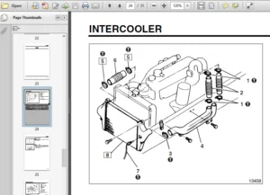
Intercooler2656
Intake Manifold2658
Front Pipe2664
Group 15 – Intake and Exhaust (2014 1/2 to 2016 Model Years)2666
Index2667
Specifications2668
Structure and Operation2669
1 Air Cleaner2669
2 Turbocharging System2670
3 EBS (Exhaust Brake System) Valve2675
Troubleshooting <General>2676
On-Vehicle Inspection and Adjustment2677
1 Exhaust Emission Condition2677
2 Cleaning and Inspection of Air Cleaner Element2677
3 Installation, Looseness, and Damage of Exhaust Pipe and Muffler2678
4 Functions of Muffler2679
Air Duct and Air Cleaner2680
<Except Crew Cab>2680
<Crew Cab>2686
Turbocharger2692
Exhaust Manifold2700
Intercooler2702
Intake Manifold2706
Front Pipe2710
Group 17 – Emission Control2712
Group 17 – Emission Control (2012 to 2014 Model Years)2713
Index2714
Specifications2715
Structure and Operation2716
1 EGR (Exhaust Gas Recirculation) System2716
2 Blowby Gas Return System2718
3 Bluetec System2719
Troubleshooting2726
On-Vehicle Inspection and Adjustment2727
1 Leakage of Diesel Exhaust Fluid2727
2 Damage and Improper Installation of Diesel Exhaust Fluid Lines2728
3 Replacement of Diesel Exhaust Fluid (AdBlue)2729
4 Measures to be Taken if Diesel Exhaust Fluid Tank is Fitted with Incorrect Diesel Exhaust Fluid Solution2730
EGR (Exhaust Gas Recirculation) Unit2731
Blowby Gas Return System2737
DEF (Diesel Exhaust Fluid) Tank2739
DPF (Diesel Particulate Filter)2743
SCR (Selective Catalytic Reduction)2747
Group 17 – Emission Control (2014 1/2 to 2016 Model Years)2751
Index2752
Specifications2753
Structure and Operation2754
1 EGR (Exhaust Gas Recirculation) System2754
2 Blowby Gas Return System2756
3 BlueTec System2757
Troubleshooting2764
On-Vehicle Inspection and Adjustment2765
1 Leakage of Diesel Exhaust Fluid2765
2 Damage and Improper Installation of Diesel Exhaust Fluid Lines2766
3 Replacement of Diesel Exhaust Fluid2767
4 Measures to be Taken if Diesel Exhaust Fluid Tank is Filled with Incorrect Diesel Exhaust Fluid Solution2768
EGR (Exhaust Gas Recirculation) Unit2769
Blowby Gas Return System2777
DEF (Diesel Exhaust Fluid) Tank2779
DPF (Diesel Particulate Filter)2783
SCR (Selective Catalytic Reduction)2787
Group 17E – BlueTec System2791
Group 17E – BlueTec System (2012 to 2014 Model Years)2792
Index2793
Structure and Operation2794
1 Overview2794
2 Electronic Control System2795
Troubleshooting 327
Inspection of Electrical Equipment 327
Installed Locations of Parts 327
Electric Circuit Diagram 327
Group 17E – BlueTec System (2014 1/2 to 2016 Model Years)2802
Index2803
Structure and Operation2804
1 Overview2804
2 Electronic Control System2805
3 Electronic Control Unit Schematic Diagram 327
Troubleshooting 327
Inspection of Electrical Equipment 327
Installed Locations of Parts 327
Electric Circuit Diagram 327
Group 21 – Clutch2817
Index2818
Troubleshooting2819
Damper2821
Group 22 – Transmission <DUONIC>2823
Group 22 – Transmission <DUONIC> (2012 Model Year)2824
Index2825
Specifications2826
Structure and Operation2828
1 Overview2828
2 Valve Body2829
3 Dual Clutch2830
4 Transmission2834
5 Synchromesh Mechanism2839
6 Transmission Power Take-off2842
Troubleshooting2844
On-Vehicle Inspection and Adjustment2848
1 Transmission Oil Leakage and Oil Quantity2848
2 Inspection of Looseness in Engine to Clutch Housing Connection2851
3 Inspection of Transmission Cooling System for Leakage, Damage and Installation Condition2851
4 Inspection of Looseness in Propeller Shaft Connection2851
5 Replacement of Transmission Oil2852
6 Replacement of Clutch Control Oil2854
7 Inspection of Transmission Mounting Cushion Rubber2855
8 Inspection of Transmission Control2856
Removal and Installation of Transmission2858
Valve Body, Dual Clutch2864
Gear Shift Unit2880
Extension Housing and Parking Brake <FE>2884
Transfer Case Adapter <FG>2894
Reverse Idler Gear <Without Large-Capacity Power Take-off>2900
Reverse Idler Gear <With Large-Capacity Power Take-off>2904
Transmission Body2908
Outer Drive Pinion2928
Inner Drive Pinion2934
Mainshaft2936
Countershaft2946
Transmission Control2956
Oil Cooler2960
Transmission Power Take-off <Standard Type>2962
Transmission Power Take-off <Large-Capacity Type>2970
Group 22 – Transmission <DUONIC> (2013 to 2014 Model Years)2980
Index2981
Transmission Power Take-off <Large-Capacity Type>2982
Group 22 – Transmission <DUONIC> (2014 1/2 to 2016 Model Years)2992
Index2993
Specifications2994
Structure and Operation2996
1 Overview2996
2 Valve Body2997
3 Dual Clutch2998
4 Transmission3002
5 Synchromesh Mechanism3007
6 Transmission Power Take-off3010
Troubleshooting3012
On-Vehicle Inspection and Adjustment3016
1 Transmission Oil Leakage and Oil Quantity3016
2 Inspection of Looseness in Engine to Clutch Housing Connection3019
3 Inspection of Transmission Cooling System for Leakage, Damage and Installation Condition3019
4 Inspection of Looseness in Propeller Shaft Connection3019
5 Replacement of Transmission Oil3020
6 Replacement of Clutch Control Oil3022
7 Inspection of Transmission Mounting Cushion Rubber3023
8 Inspection of Transmission Control3024
Removal and Installation of Transmission3026
Valve Body, Dual Clutch3032
Gear Shift Unit3048
Extension Housing and Parking Brake <FE>3052
Transfer Case Adapater <FG>3061
Reverse Idler Gear <Without Large-Capacity Power Take-off>3068
Reverse Idler Gear <With Large-Capacity Power Take-off>3072
Transmission Body3076
Outer Drive Pinion3096
Inner Drive Pinion3102
Mainshaft3104
Countershaft3114
Transmission Control3124
Oil Cooler3128
Transmission Power Take-off <Standard Type>3134
Transmission Power Take-off <Large-Capacity Type>3142
Group 22E – DUONIC3152
Group 22E – DUONIC (2012 to 2014 Model Years)3153
Index3154
Specifications3155
Structure and Operation3157
1 Overview3157
2 Electronic Control System3158
3 Electronic Control Unit Schematic Diagram3167
Troubleshooting3169
1 Inspection Based on Diagnosis Codes3169
2 Service Data (Actual Measurements) of Fuso Diagnostics3291
3 Actuator Tests Available in Fuso Diagnostics3303
4 Inputs and Outputs to/from Electronic Control Unit3304
5 Coding Data in Electronic Control Unit3305
6 Initialization of DUONIC System3306
7 Troubleshooting by Symptom3309
Inspection of Electrical Parts3311
Installed Locations of Parts3317
Electric Circuit Diagram3339
Group 22E – DUONIC (2014 1/2 to 2016 Model Years)3341
Index3342
Specifications3343
Structure and Operation3345
1 Overview3345
2 Electronic Control System3346
3 Electronic Control Unit Schematic Diagram3357
Troubleshooting3359
1 Inspections based on Diagnosis Codes3359
2 Fuso Diagnostics Service Data (Actual Values)3483
3 Fuso Diagnostics Actuator Test (Actuations)3506
4 Electronic Control Unit Input/Output Table3507
5 Coding Data in Electronic Control Unit3508
6 Initialization of DUONIC System3509
7 Troubleshooting by Symptom3513
Inspection of Electrical Parts4276
Installed Locations of Parts4276
Electric Circuit Diagram4276
Group 24 – Transfer3515
Index3516
Specifications3517
Structure and Operation3518
1 Transfer3518
Troubleshooting3519
On-Vehicle Inspection and Adjustment3521
1 Inspection of Transmission and Transfer Oil Leakage3521
2 Inspection of Looseness in Transmission and Transfer Mounting Bolts3521
3 Inspection of Play and Looseness in Companion Flange3522
4 Inspection and Replacement of Transfer Oil3523
Removal and Installation of Transmission (With Transfer)3525
Removal and Installation of Transfer3531
Front Drive3533
Rear Drive3539
Transfer3543
Group 25 – Propeller Shaft3551
Index3552
Specifications3553
Structure and Operation3553
1 Configuration of Propeller Shaft Connection3553
2 Propeller Shaft <Without Center Bearing>3554
Troubleshooting3556
Removal and Installation of Propeller Shaft3557
<Between T/M (Or Transfer) and Rear Axle>3557
<Between Front Axle and Transfer>3559
Propeller Shaft3561
<P2>3561
<P3>3567
Group 26A – Front Axle <FE>3578
Index3579
Specifications3580
Structure and Operation3581
1 Wheel Hub and Rotor3581
2 Knuckle and Kingpin, Front Axle3582
Troubleshooting3583
On-Vehicle Inspection and Adjustment3584
1 Inspection and Adjustment of Wheel Alignment3584
2 Inspection and Adjustment of Steering Angle3588
3 Inspection of Side Slip3588
4 Inspection of Tie Rod End Ball Joint3589
5 Inspection of Wheel Bearing for Play3589
6 Inspection of Knuckle Joint for Play3589
Wheel Hub and Rotor3590
Knuckle and Kingpin, Front Axle3600
Tie Rod3610
Group 26B – Front Axle <FG>3612
Index3613
Specifications3614
Structure and Operation3614
1 Wheel Hub and Brake Drum3614
2 Free Wheel Hub3615
3 Drive Shaft and Steering Knuckle, Axle Housing3616
4 Reduction and Differential3617
Troubleshooting3618
On-Vehicle Inspection and Adjustment3622
1 Inspection and Adjustment of Wheel Alignment3622
2 Inspection and Adjustment of Steering Angle3626
3 Inspection of Side Slip3626
4 Inspection of Tie Rod End Ball Joint3627
5 Inspection and Replacement of Differential Oil3628
6 Inspection of Wheel Bearing for Play3629
7 Inspection of Knuckle Joint for Play3629
Wheel Hub and Brake Drum3630
Drive Shaft and Steering Knuckle3644
Tie Rod3650
Axle Housing3652
Reduction and Differential3654
Group 27 – Rear Axle3668
Group 27 – Rear Axle (2012 to 2014 1/2 Model Years)3669
Index3670
Specifications3671
Structure and Operation3672
1 Wheel Hub and Rotor3672
2 Wheel Hub and Brake Drum3673
3 Reduction and Differential3674
4 Limited Slip Differential3675
Troubleshooting3677
On-Vehicle Inspection and Adjustment3679
1 Inspection and Replacement of Axle Oil3679
2 Inspection of Wheel Bearing for Play3680
Wheel Hub and Rotor3681
<FE52>3681
<FEC7, FEC9>3693
Wheel Hub and Brake Drum3705
Axle Housing3715
Reduction and Differential3719
Group 27 – Rear Axle (2015 to 2016 Model Years)3744
Index3745
Specifications3746
Structure and Operation3747
1 Wheel Hub and Rotor3747
Wheel Hub and Rotor3748
<FE52>3748
<FEC7, FEC9, FECX>3760
Group 31 – Wheel and Tire3771
Index3772
Specifications3773
Troubleshooting3774
On-Vehicle Inspection and Adjustment3775
1 Inspection of Looseness in Wheel Nuts3775
2 Inspection of Tire3776
Wheel and Tire3779
Group 33 – Front Suspension3786
Group 33 – Front Suspension (2012 to 2014 1/2/ Model Years)3787
Index3788
Structure and Operation3789
1 Front Suspension Elements3789
Troubleshooting3790
Stabilizer <FE>3791
Shock Absorber3793
<FE>3793
<FG>3795
Leaf Spring3797
<FE>3797
<FG>3805
Group 33 – Front Suspension (2015 to 2016 Model Years)3810
Index3811
Structure and Operation3812
1 Front Suspension Elements3812
Leaf Spring3814
<FE>3814
<FG>3822
Group 34 – Rear Suspension3827
Index3828
Structure and Operation3829
1 Rear Suspension Elements3829
Troubleshooting3830
Stabilizer <FEC7, FEC9>3831
Shock Aborber3832
Leaf Spring3833
Group 35 – Brake3847
Group 35 – Brake (2012 to 2014 1/2 Model Years)3848
Index3849
Specifications3850
Structure and Operation3852
1 Brake System3852
2 Vacuum Pump3853
3 Vacuum Booster and Brake Master Cylinder3854
4 Front Disc Brake <FE>3858
5 Front Drum Brake <FG>3859
6 Rear Disc Brake <FE>3862
7 Rear Drum Brake <FG>3863
Troubleshooting3864
On-Vehicle Inspection and Adjustment3868
1 Replacement of Brake Fluid3868
2 Air Bleeding of Brake System3870
3 Inspection and Adjustment of Brake Pedal3874
4 Inspection and Replacement of Disc Brake Pad <FE>3876
5 Measurement of Disc Brake Drag Torque <FE>3878
6 Inspection of Drum Brake Lining Thickness <FG>3878
7 Initial Setting of Clearance Between Brake Drum and Shoe <FG>3879
8 Inspection of Check Valve in Vacuum Line Hose3880
9 Inspection of Vacuum Pump3881
10 Inspection of Vacuum Booster3881
Brake Master Cylinder3886
Brake Pedal & Vacuum Booster3888
Front Disc Brake3892
Front Drum Brake3898
Rear Disc Brake3906
Rear Drum Brake3912
Group 35 – Brake (2015 to 2016 Model Years)3918
Index3919
On-Vehicle Inspection and Adjustment3920
1 Inspection and Adjustment of Brake Pedal3920
2 Inspection of Vacuum Booster3922
Group 35E – Anti-lock Brake System (ABS)3927
Group 35E – Anti-lock Brake System (ABS) (2012 to 2014 Model Years)3928
Index3929
Specifications3930
Structure and Operation3932
1 Overview3932
2 Electronic Control System3949
3 Electronic Control Unit Schematic Diagram3952
Troubleshooting3954
1 Inspections According to Diagnosis Codes3954
2 Fuso Diagnostics Service Data (Measured Values)3976
3 Actuator Test (Control) Using Fuso Diagnostics3977
4 Electronic Control Unit Coding3978
5 Rewriting of Coding Data3978
6 Electronic Control Unit Input/Output Diagram3978
On-Vehicle Inspection and Adjustment3980
1 Functional Check3980
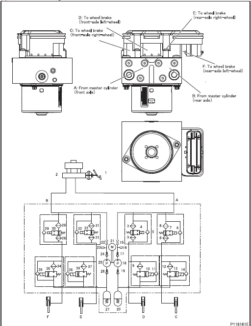
2 Inspection of Hydraulic Unit (Electronic Control Unit) Operation3981
3 Inspection After Replacing or Removing/Installing Hydraulic Unit (Electronic Control Unit)3982
Hydraulic Unit (Electronic Control Unit)3984
Inspection of Electrical Parts3988
Installed Locations of Parts3990
Electrical Circuit Diagram4002
Group 35E – Anti-lock Brake System (ABS) (2014 1/2 to 2016 Model Years)4004
Index4005
Specifications4006
Structure and Operation4008
1 Overview4008
2 Electronic Control System4025
3 Electronic Control Unit Schematic Diagram4028
Troubleshooting4030
1 Inspections Based on Diagnosis Codes4030
2 Fuso Diagnostics Service Data (Actual Values)4054
3 Fuso Diagnostics Actuator Test (Actuations)4058
4 Coding Data in Electronic Control Unit4059
5 Electronic Control Unit Input/Output Table4059
On-Vehicle Inspection and Adjustment4060
1 Functional Check4060
2 Inspection of Hydraulic Unit (Electronic Control Unit) Operation4061
3 Inspection After Replacing or Removing/Installing Hydraulic Unit (Electronic Control Unit)4062
Hydraulic Unit (Electronic Control Unit)4064
Inspection of Electrical Parts4276
Installed Locations of Parts4276
Electric Circuit Diagram4276
Group 36 – Parking Brake4067
Index4068
Specifications4069
Structure and Operation4070
1 Components and Parts4070
2 Parking Brake Lever4070
3 Parking Brake4071
Troubleshooting4072
On-Vehicle Inspection and Adjustment4073
1 Inspection of Parking Brake Drum Mounting for Looseness4073
2 Adjustment of Parking Brake Shoe Clearance4073
3 Inspection and Adjustment of Parking Brake Lever4074
Parking Brake Control4077
Parking Brake4079
Group 37 – Steering4081
Index4082
Specifications4083
Structure and Operation4085
1 Steering System4085
2 Oil Flow4085
3 Power Steering Gear Assembly4086
4 Power Steering Oil Pump4088
Troubleshooting4089
On-Vehicle Inspection and Adjustment4091
1 Steering Wheel Play4091
2 Steering Column Looseness4091
3 Inspection of Rods and Arms for Looseness4091
4 Inspection of Power Steering System Mounts for Looseness4092
5 Inspection and Replacement of Power Steering Oil4092
6 Performance Verification Test of Power Steering System4094
7 Inspection of Drag Link Ball Joint4095
8 Inspection of Steering Wheel Operation During Running4095
Steering Column4097
Power Steering Gear Assembly and Drag Link4103
Power Steering Oil Tank4119
Group 41 – Bumper and Frame4120
Index4121
Specifications4122
Structure and Operation4123
Front Bumper4124
Frame4126
Group 42 – Cab4130
Group 42 – Cab (2012 to 2014 1/2 Model Years)4131
Index4132
Specifications4133
Structure and Operation4134
1 Front Cab Mounting4134
2 Rear Cab Mounting <Except Crew Cab>4135
3 Center and Rear Cab Mountings <Crew Cab>4135
4 Cab Tilt Link <Except Crew Cab>4136
Troubleshooting4137
On-Vehicle Inspection and Adjustment4139
1 Adjustment of Cab Tilt System <Except Crew Cab>4139
Removal and Installation of Cab4141
<Except Crew Cab>4141
<Crew Cab>4145
Front Cab Mounting4149
<Except Crew Cab>4149
<Crew Cab>4151
Rear Cab Mounting <Except Crew Cab>4153
Center and Rear Cab Mountings <Crew Cab>4155
Cab Tilt Link <Except Crew Cab>4157
Cab Stay <Except Crew Cab>4159
Group 42 – Cab (2015 to 2016 Model Years)4160
Index4161
Cab Tilt Link <Except Crew Cab>4162
Group 43 – Door4165
Index4166
Specifications4167
Structure and Operation4168
1 Front Door Lock System4168
2 Rear Door Lock System <Crew Cab>4168
3 Front Door Glass Opening and Closing Mechanism4169
4 Rear Door Glass Opening and Closing Mechanism <Crew Cab>4170
5 Keyless Entry System4171
Troubleshooting4175
On-Vehicle Inspection and Adjustment4179
1 Adjustment of Front Door Alignment4179
2 Adjustment of Rear Door Alignment <Crew Cab>4181
3 Inspection of Keyless Entry System4183
4 Method of Transmitting Code to Keyless Entry Electrical Control Unit4184
Front Door4187
Rear Door <Crew Cab>4195
Group 51 – Exterior4202
Index4203
Structure and Operation4204
1 Wiper and Washer System4204
Troubleshooting4205
Mirror4207
Wiper and Washer4209
Front Cover4211
Front Grille, Front Corner Panel and Headlamp4213
Fender <FG>4218
Step4219
Garnish <Crew Cab>4221
Wheel House4222
Window Glass4223
Group 52 – Interior4226
Group 52 – Interior (2012 Model Year)4227
Index4228
Driver Seat4229
Passenger Seat4230
Rear Seat <Crew Cab>4231
Seat Belt4233
Instrument Panel4239
Trim and Scuff Plate4255
<Except Crew Cab>4255
<Crew Cab>4259
Head Lining4263
<Except Crew Cab>4263
<Crew Cab>4267
Group 52 – Interior (2013 to 2016 Model Years)4270
Index4271
Driver Seat4272
Passenger Seat4274
Group 54 – Electrical4276
Group 54 – Electrical (2012 to 2014 Model Years)4277
Index4278
54-00A – General 18
54-00B – Specifications4281
Specifications4282
54-00C – Structure and Operation4285
1 Starter4286
2 Alternator4287
3 Headlamps4289
4 Meter Cluster4290
5 Signal Detect and Actuation Modules4302
6 Immobilizer4322
54-00D – Troubleshooting4325
Troubleshooting4326
54-01 – Power, Charge and Ground Circuit4353
High-Current Fuse Box4354
Fuse Box4356
105 – SAM Internal Circuit4358
110 – Power Circuit4360
115 – Reserve Power Circuit4374
125 – Battery Charging Circuit4375
130 – Ground4376
54-02 – Engine Starting, Stopping and Preheating Circuit4391
210 – Engine Starting Circuit4392
220 – Engine Preheating Circuit 328
54-03 – Lighting Circuit4394
310 – Headlamp Circuit4395
313 – Daytime Running Light Circuit4396
315 – Fog Lamp Circuit4397
320 – Tail, Parking and License Plate Lamps Circuit4398
325 – Stop Lamp Circuit4399
330 – Turn Signal and Hazard Lamp Circuit4400
340 – Backup Lamp Circuit4401
345 – Cab Lamp Circuit4403
348 – Illumination Lamp Circuit4405
349 – Identification and Side Marker Lamp Circuit4406
352 – Van Body Dome Light Circuit4407
54-04 Meter Circuit4408
401 – Meter Cluster Internal Circuit4409
410 – Tachometer Circuit4411
412 – Speedometer Circuit4412
415 – Tachograph Circuit4413
420 – Fuel Gauge Circuit4414
425 – Water Temperature Gauge Circuit4415
54-05 – Indicator and Warning Lamp Circuit4416
510 – Parking Brake Indicator Circuit4417
515 – Brake Warning Circuit4418
536 – Engine Oil Pressure Warning Circuit4419
537 – Overheating Warning Circuit4420
550 – Cab Tilt Warning Circuit4421
554 – Starter Key Removal Reminder Alarm Circuit4422
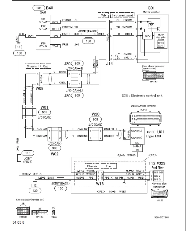
566 – Fuel Filter Circuit4423
54-06 – Cab Side Electrical Circuit4424
610 – Cigarette Lighter Circuit4425
612 – Audio Circuit4426
614 – Wiper and Washer Circuit4427
616 – Horn Circuit4428
620 – Heater and Air-conditioner Circuit4429
622 – Power Window and Central Door Lock Circuit4431
629 – Mirror Heater Circuit4432
654 – Keyless Entry Circuit4433
54-08 – Engine and Transmission Side Electrical Circuit4434
810 – Four-Wheel Drive Circuit4435
850 – Transmission Power Take-off Circuit4436
54-09 – Other Circuit4437
905 – Joint Connector (J/C)4438
Common Rail System Electric Circuit Diagram 328
DUONIC System Electric Circuit Diagram3153
Anti-lock Brake System Electric Circuit Diagram3928
Fully Automatic Air-conditioner System Electric Circuit Diagram5197
54-10 – Electrical Equipment Installation Positions4440
Cab Side4441
A – Switch and Sensor4441
B – Relay and Electronic Control Unit4445
C – Meter and Motor4449
D – Air-conditioner4451
E – Door4455
F – Roof4456
G – Cab4457
H – Tilt4458
J – Joints of Main Harness Connectors4459
P – Others4463
Engine and Transmission4465
R – Engine4465
S – Transmission4467
Chassis Side4469
T – Switch and Sensor4469
U – Fuse, Relay and Electronic Control Unit4475
V – Magnetic Valve, Motor and Buzzer4477
W – Joints of Main Harness Connectors4479
X – Others4483
54-11 – Inspection of Electrical Equipment4488
#001 to #179 Switch4489
#180 to #249 Relay4494
#250 to #349 Sensor4495
#350 to #409 Control Unit4498
#410 to #509 Motor4499
#510 to #539 Actuator4502
#560 to #609 Magnetic Valve4503
#610 to #649 Buzzer, Horn4504
#650 to #699 Lamp4505
#750 to #859 Other4506
#860 Battery4509
#890 Meter4512
54-12 – Starter and Alternator4514
#930 Starter4515
#940 Alternator4533
54-13 – On-Vehicle Inspection and Adjustment4536
#950 Inspection of Alternator4537
#951 Inspection of Regulator4538
#960 Headlamp Aiming4539
#961 Fog Lamp Aiming4541
#984 Inspection of Immobilizer4543
#985 Inspection of Signal Detect and Actuation Modules4553
#986 Inspection of Meter Cluster4595
54-14 – Connector Configuration Chart4598
Connector Configuration Chart4599
Group 54 – Electrical (2014 1/2 to 2016 Model Years)4696
Index4697
54-00A – General 17
54-00B – Specifications4700
Specifications4701
54-00C – Structure and Operation4704
1 Starter4705
2 Alternator4706
3 Headlamps4708
54-00D – Troubleshooting4709
Troubleshooting4710
54-01 – Power, Charge and Ground Circuit4740
High-Current Fuse Box4741
Fuse Box4743
105 – SAM Internal Circuit4745
110 – Power Circuit4747
115 – Reserve Power Circuit4762
125 – Battery Charging Circuit4763
130 – Ground4764
54-02 – Engine Starting, Stopping and Preheating Circuit4780
210 – Engine Starting Circuit4781
220 – Engine Preheating Circuit4834
54-03 – Lighting Circuit4783
310 – Headlamp Circuit4784
313 – Daytime Running Light Circuit4785
315 – Fog Lamp Circuit4786
320 – Tail, Parking and License Plate Lamps Circuit4787
325 – Stop Lamp Circuit4788
330 – Turn Signal and Hazard Lamp Circuit4789
340 – Backup Lamp Circuit4790
345 – Cab Lamp Circuit4792
348 – Illumination Lamp Circuit4794
349 – Identification and Side Marker Lamp Circuit4795
352 – Van Body Dome Light Circuit4796
54-04 – Meter Circuit4797
401 – Meter Cluster Internal Circuit4798
410 – Tachometer Circuit4800
412 – Speedometer Circuit4801
415 – Tachograph Circuit4802
420 – Fuel Gauge Circuit4803
425 – Water Temperature Gauge Circuit4804
54-05 – Indicator and Warning Lamp Circuit4805
510 – Parking Brake Indicator Circuit4806
515 – Brake Warning Circuit4807
536 – Engine Oil Pressure Warning Circuit4808
537 – Overheating Warning Circuit4809
550 – Cab Tilt Warning Circuit4810
554 – Starter Key Removal Reminder Alarm Circuit4811
566 – Fuel Filter Circuit4812
54-06 – Cab Side Electrical Circuit4813
610 – Cigarette Lighter Circuit4814
612 – Audio Circuit4815
614 – Wiper and Washer Circuit4816
616 – Horn Circuit4817
620 – Heater and Air-conditioner Circuit4818
622 – Power Window and Central Door Lock Circuit4823
629 – Mirror Heater Circuit4824
654 – Keyless Entry Circuit4825
54-07 – Chassis Side Electrical Circuit4826
790 – Anti-lock Brake System4827
54-08 – Engine and Transmission Side Electrical Circuit4829
810 – Four-Wheel Drive Circuit4830
850 – Transmission Power Take-off Circuit4831
873 – DUONIC System Electric Circuit4832
880 – Common Rail System Electric Circuit4834
54-09 – Other Circuit4841
905 – Joint Connector (J/C)4842
54-10 – Electrical Equipment Installation Positions4846
Cab Side4847
A – Switch and Sensor4847
B – Relay and Electronic Control Unit4851
C – Meter and Motor4855
D – Air-conditioner4857
E – Door4861
F – Roof4862
G – Cab4863
H – Tilt4864
J – Joints of Main Harness Connectors4865
P – Others4869
Engine and Transmission4871
R – Engine4871
S – Transmission4873
Chassis Side4875
T – Switch and Sensor4875
U – Fuse, Relay and Electronic Control Unit4881
V – Magnetic Valve, Motor and Buzzer4883
W – Joints of Main Harness Connectors4885
X – Others4889
54-11 – Inspection of Electrical Equipment4893
#001 to #179 Switch4894
#180 to #249 Relay4899
#250 to #349 Sensor4900
#350 to #409 Control Unit4908
#410 to #509 Motor4909
#510 to #539 Actuator4912
#560 to #609 Magnetic Valve4914
#610 to #649 Buzzer, Horn4915
#650 to #699 Lamp4916
#750 to #859 Other4917
#860 Battery4921
#890 Meter4924
54-12 – Starter and Alternator4925
#930 Starter4926
#940 Alternator4944
54-13 – On-Vehicle Inspection and Adjustment4946
#950 Inspection of Alternator4947
#951 Inspection of Regulator4948
#960 Headlamp Aiming4949
#961 Fog Lamp Aiming4951
54-14 – Connector Configuration Chart4952
Connector Configuration Chart4953
Group 54EI – Immobilizer (2014 1/2 to 2016 Model Years)5052
Index5053
Structure and Operation5054
1 Overview5054
2 Electronic Control System5055
3 Electronic Control Circuit Diagram5056
Troubleshooting5058
1 Inspection Based on Diagnosis Codes5058
2 Fuso Diagnostics Service Data (Measured Values)5061
Initial Settings of Immobilizer5062
1 Connecting the Fuso Diagnostics5062
2 Selection of the Setting of Immobilizer5062
3 Various Operations (Initial Key Registration, Additional Key Registration, Secret Key Registration, Key Information Deletion)5063
4 Additional Starter Key Registration (Up to 6 Keys Can be Registered)5067
5 New Starter Key Registration After All of Starter Keys Have Been Lost5068
Inspection of Electrical Parts4696
Installed Locations of Parts4696
Electric Circuit Diagram4696
Group 54EM – Meter Cluster (2014 1/2 to 2016 Model Years)5069
Index5070
Specifications5071
Structure and Operation5073
1 Overview5073
2 Electronic Control System5074
3 Electronic Control Unit Circuit Diagram5084
Troubleshooting5085
1 Inspection Based on Diagnosis Codes5085
2 Fuso Diagnostics Service Data (Actual Values)5087
3 Fuso Diagnotics Actuator Test (Actuations)5087
4 Coding Data in Electronic Control Unit5087
5 Electronic Control Unit Input/Output Table5088
Inspection of Electrical Parts4696
Installed Locations of Parts4696
Electric Circuit Diagram4696
Group 54ES – Signal Detect and Actuation Modules (2014 1/2 to 2016 Model Years)5089
Index5090
Structure and Operation5091
1 Overview5091
2 Electronic Control System5093
3 Electronic Control Unit Circuit Diagram5101
4 Diagnosis Code Occurrence Condition Range (Lost of Output Current Threshold Values)5110
Troubleshooting5113
1 Inspection Based on Diagnosis Codes5113
2 Fuso Diagnostics Service Data (Actual Values)5140
3 Fuso Diagnostics Actuator Test (Actuations)5150
4 Coding Data in Electronic Control Unit5150
5 Electronic Control Unit Input/Output Table5151
6 Confirmation Items Before Replacing the Signal Detect and Actuation Module5153
7 Symptoms and Inspection Procedures When Warning Lamp (Red or Amber) Illuminates5156
Inspection of Relays in Signal Detect and Actuation Module5159
Inspection of Electrical Parts4696
Installed Locations of Parts4696
Electric Circuit Diagram4696
Group 55 – Heater, Air-conditioner, and Ventilation5160
Index5161
Specifications5162
Structure and Operation5163
1 Heater5163
2 Air Conditioner5164
3 Compressor5165
4 Air Duct5168
5 Heater Control5169
6 Rear Heater <Crew Cab>5173
Troubleshooting5174
On-Vehicle Inspection and Adjustment5178
1 Operation Check of Air-Conditioner5178
2 Recovery of Refrigerant5182
3 Recharging the System with Refrigerant5183
Connecting Air-Conditioner Piping5185
Compressor5186
Condenser, Receiver5187
Heater Control <Manual Air-Conditioner>5189
Air Duct5193
Heater and Cooling Unit, Blower5194
Rear Heater <Crew Cab>5195
Group 55E – Full Automatic Air-conditioner5196
Group 55E – Full Automatic Air-conditioner (2012 to 2014 Model Years)5197
Index5198
Specifications5199
Structure and Operation5201
1 Overview5201
2 Electronic Control System5202
3 Electronic Control Unit Schematic Diagram5204
Troubleshooting5205
1 Inspection According to Diagnosis Code (Trouble Codes)5205
2 Fuso Diagnostics Service Data (Measured Values)5211
3 Actuator Test (Control) Using Fuso Diagnostics5213
4 Electronic Control Unit Input/Output Table5215
Inspection of Electrical Parts5217
Installed Locations of Parts5223
Electrical Circuit Diagram5241
Group 55E – Full Automatic Air-conditioner (2014 1/2 to 2016 Model Years)5243
Index5244
Specifications5160
Structure and Operation5245
1 Overview5245
2 Electronic Control System5246
3 Electronic Control Unit Schematic Diagram5248
Troubleshooting5249
1 Inspection Based on Diagnosis Codes5249
2 Fuso Diagnostics Service Data (Actual Values)5255
3 Fuso Diagnostics Actuator Test (Actuations)5258
4 Electronic Control Unit Input/Output Table5260
Inspection of Electrical Parts4696
Installed Locations of Parts4696
Electrical Circuit Diagram4696
IMAGES PREVIEW OF THE MANUAL:
2012-2016 MITSUBISHI FUSO CANTER FE FG SERIES TRUCK SERVICE MANUAL – PDF DOWNLOAD:
PLEASE NOTE:
- This is the same manual used by the DEALERSHIPS to SERVICE your vehicle.
- The manual can be all yours – Once payment is complete, you will be taken to the download page from where you can download the manual. All in 2-5 minutes time!!
- Need any other service / repair / parts manual, please feel free to contact us at [email protected] . We may surprise you with a nice offer
S.V