
2012 Volvo XC60 Wiring Diagram Manual TP 39215202 – Complete Electrical Schematics PDF
Original price was: $34.95.$19.95Current price is: $19.95.
Complete 2012 Volvo XC60 wiring diagram manual TP 39215202 covering electrical distribution, fuses, relays, ground connections, control modules, CAN/LIN/MOST networks, and system-by-system schematics for all engine variants.
Description
When electrical faults strike a 2012 Volvo XC60, guesswork is expensive. The 2012 Volvo XC60 Wiring Diagram Manual TP 39215202 puts the complete electrical architecture of this vehicle at your fingertips — every circuit, every connector, every ground point, every relay and fuse location. This is the same wiring information used by Volvo technicians, covering the full range of 2012 XC60 configurations from the 4-cylinder turbo to the 6-cylinder engines and the 5-cylinder diesel.
What This Volvo XC60 Wiring Diagram Manual Covers
The manual is organized by vehicle system group, following Volvo’s standard numbering system. Whether you’re tracing a parasitic draw, diagnosing a no-start condition, repairing a lighting fault, or installing accessories, the 2012 XC60 wiring diagrams in this manual show exactly how the circuit is built and where every wire terminates.
Electrical Distribution and Power Flow
Before you can diagnose anything, you need to understand how power moves through the vehicle. The manual opens with complete electrical distribution overviews — one for vehicles without the Start/Stop function and one for vehicles with it. Separate distribution box overviews cover the engine compartment, passenger compartment, and cargo compartment. Fuse and relay locations are documented in detail, including the Central Electronic Module (CEM) fuses, cold zone distribution box, and battery main fuses.
Complete Fuse and Relay Documentation
Every fuse in the 2012 Volvo XC60 is listed with its function, amperage rating, and the circuits it protects. The manual breaks this down by location:
- Engine compartment distribution box (F1–F44, plus main fuses)
- Central Electronic Module (CEM) fuses (F1–F24)
- Passenger compartment distribution box (F1–F30)
- Cold zone distribution box (F1–MF2)
- Cargo compartment distribution box (F1–FA11)
- Battery main fuses (PF1–PF2)
Relay locations and functions are similarly documented for the engine compartment (R1–R13), passenger compartment, and cargo compartment.
Ground Connections
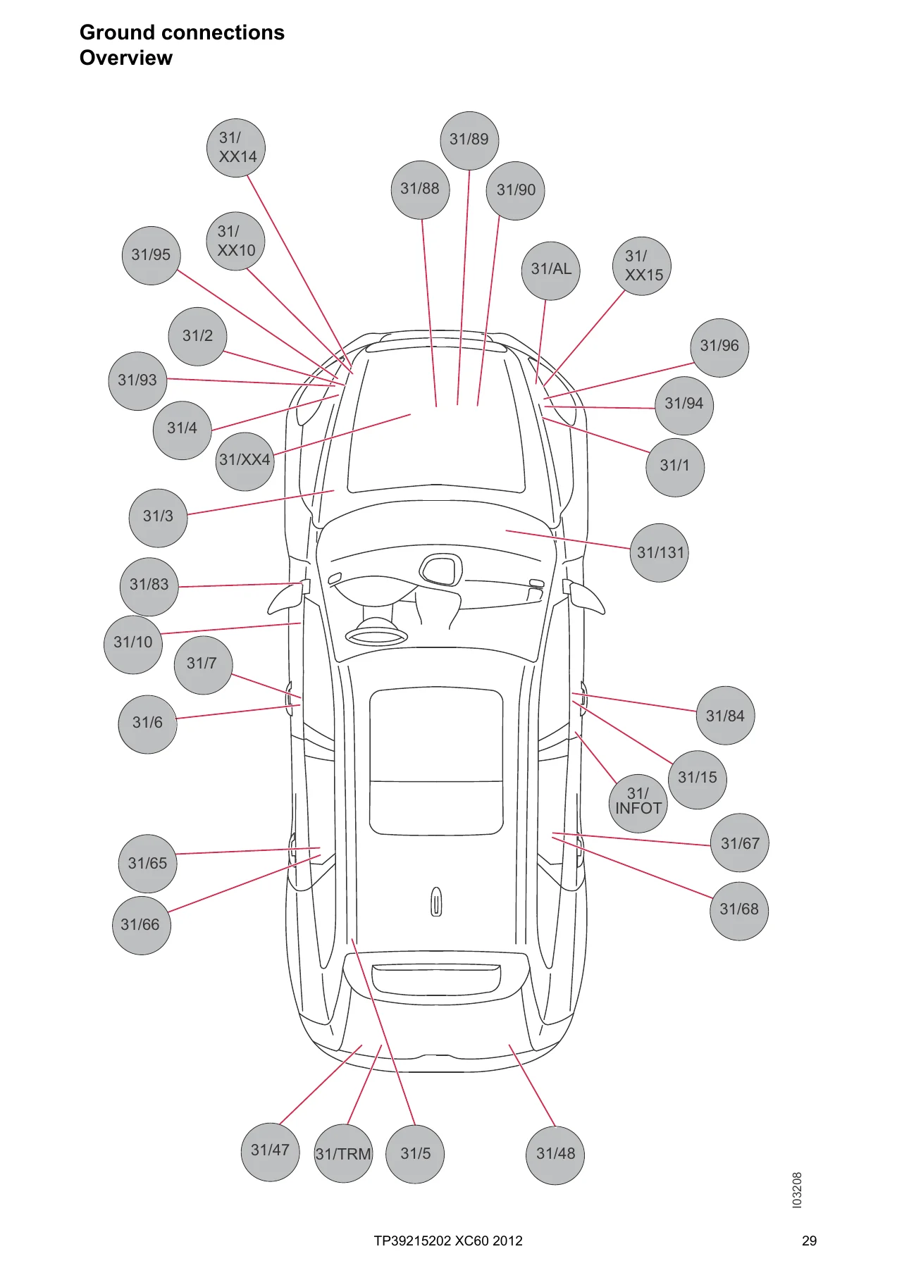
Ground faults are among the most frustrating electrical problems to chase. This manual identifies every ground connection point in the vehicle, from 31/1 (PTC ground) through 31/TRM (accessories ground). Each ground connection lists the components that terminate at that point, making it possible to identify shared grounds and the symptoms that a single bad ground can produce across multiple systems.
Control Modules and Data Communication
Modern Volvo vehicles rely on networked control modules, and the 2012 XC60 is no exception. The manual covers the complete module network:
- High-speed CAN network topology
- Intermediate-speed CAN (LHD and RHD variants)
- Local CAN network
- MOST network (infotainment)
- LIN network
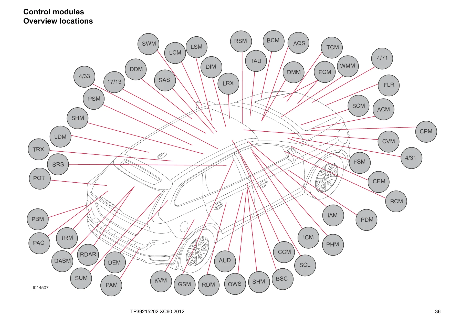
Module locations are shown both in overview diagrams and in designations lists, covering the CEM, ECM, TCM, BCM, SRS, DDM, PDM, LDM, RDM, KVM, and more.
System-by-System Wiring Diagrams
The core of the manual is the system-specific wiring diagrams. Each diagram shows the complete circuit from power source through fuses, relays, switches, modules, and components to ground. The manual is organized by Volvo’s group numbering:
Group 26 — Cooling System: Cooling fan circuits for 4-cylinder turbo, 5-cylinder diesel, and 6-cylinder engines.
Group 27 — Engine Controls: Cruise control circuits for all engine variants and complete Start/Stop function wiring for 4-cylinder 1.6L turbo, 4-cylinder 1.6L diesel, and 5-cylinder diesel models.
Group 28 — Ignition and Control System: Engine management wiring for 5-cylinder diesel, 4-cylinder turbo 2.0L, 6-cylinder, 6-cylinder B6324S4, and 6-cylinder turbo. Also includes emission control circuits for 4-cylinder turbo and 6-cylinder engines.
Group 32 — Alternator and Voltage Regulator: Power supply and charging circuits for all engine variants.
Group 33 — Starting System: Starter motor circuits for 4-cylinder turbo and 5- and 6-cylinder engines.
Group 35 — Lighting: High and low beam (including Dual Xenon), beam length adjustment, running/parking lights, tail lights, fog lights, brake lights, reversing lights, follow-me-home lighting, interior lighting, active headlight, door sill trim lighting, and auxiliary lights.
Group 36 — Additional Electrical Equipment: Rain sensor, direction indicators and hazard warning flashers, wiper/washer systems (windshield, headlights, rear window), horn, keyless vehicle system, anti-theft alarm, parking assistance, collision warning, tire pressure monitoring (TPMS), and alcohol lock.
Group 37 — Wiring and Fuses: Diagnostics system, 12V outlets, towbar/tow hitch cable harnesses (4-pin, 7-pin, and 13-pin), and USB unit.
Group 38 — Instruments: Seat belt reminder and driver information module.
Group 39 — Other: Audio systems (High/Premium and standard), cellular phone, DAB radio, rear seat entertainment (RSE), multimedia monitors, TV receiver, Bluetooth handsfree, navigation system, satellite radio, and parking cameras (front, rear, and wide angle).
Group 43 — Transmission: Automatic transmission TF-80SC, M66 and MMT6 manual transmissions, automatic transmission MPS6, and differential electronic module (DEM).
Group 55 — Parking Brake: Electric parking brake circuits.
Group 59 — Brake System: Brake control system and DSTC.
Group 64 — Steering: Speed-dependent power steering.
Group 76 — Shock Absorbers: Four-C continuously controlled damping.
Group 83 — Doors and Openings: Central locking (front doors LHD/RHD, rear doors, tailgate with and without power operation, fuel filler flap), signal receiver, power windows (front and rear), and power sunroof.
Group 84 — Exterior Decorative Elements: Power door mirrors (LHD/RHD), heated door mirrors, blind spot information system (LHD/RHD), and heated rear window.
Group 85 — Interior Equipment: Power driver’s seat with memory (LHD/RHD), power passenger seat (LHD/RHD), heated front seats (with and without fans), and heated rear seat.
Group 87 — Climate Control System: Complete climate control wiring for 4-cylinder, 5-cylinder, and 6-cylinder engines, PTC elements, parking heater, and remote start.
Group 88 — Internal Equipment: Auto-dimming rearview mirror, supplemental restraint system (SRS), remote control for garage door opener, and power folding headrest.
Group 89 — Body Other: Radiator masking blind.
Connectors, Branching Points, and Harness Routing
Beyond the circuit diagrams, the manual includes a complete connector reference showing pin assignments, wire colors, and connection destinations. Branching points (numbered junctions where circuits split) are listed with all components connected to each point. The cable harness routing section shows the physical path of every harness in the vehicle — engine, dashboard, floor, infotainment, roof, center console, tunnel, doors, tailgate, and rear axle.
Component Illustrations and Index
Every component in the manual is illustrated and listed in numerical order, making it easy to identify unfamiliar parts. The index provides quick navigation to any system or component group.
Why This 2012 Volvo XC60 Wiring Diagram Manual Matters
Electrical diagnosis without a wiring diagram is gambling. This manual eliminates the guesswork by showing you exactly how every circuit is designed to work. That means:
- You can trace a fault logically instead of replacing parts and hoping
- You can identify shared grounds and power feeds that might explain multiple symptoms
- You can verify wire colors and pin positions before probing connectors
- You can install aftermarket accessories without cutting the wrong wire
- You can understand CAN, LIN, and MOST network topology when diagnosing communication faults
The 2012 Volvo XC60 Wiring Diagram Manual TP 39215202 is particularly valuable because it covers the full range of 2012 configurations, including LHD and RHD variants, multiple engine options, and the Start/Stop function. Whether you’re a professional technician, a serious DIYer, or a shop that services Volvo vehicles, this manual gives you the information you need to diagnose and repair electrical faults correctly.
Get Instant Access to the 2012 Volvo XC60 Wiring Diagram Manual
IMAGES PREVIEW
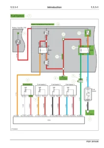
This manual is delivered as a downloadable PDF file. There’s no shipping wait, no physical book to keep track of, and no subscription. You get instant access after payment — view it on any device, print the pages you need for the shop, and keep the file for as long as you own the vehicle. The 2012 Volvo XC60 wiring diagrams in this manual are the same ones professional technicians use to diagnose electrical faults accurately and efficiently.
Reviews
There are no reviews yet.