

Hunter P201 Wiring Diagrams Manual 2019.05 – D20T JE4D25 4K22T Electrical Circuits PDF
Original price was: $34.95.$19.95Current price is: $19.95.
Hunter P201 wiring diagrams manual dated P201 2019.05 covering D20T, JE4D25-G5/G6 and 4K22T circuits, fuses, grounds, harness connectors, PEPS and non-PEPS body electrics.
Description
Hunter P201 Wiring Diagrams Manual 2019.05 – D20T JE4D25 4K22T Electrical Circuits PDF
The Hunter P201 Wiring Diagrams Manual 2019.05 – D20T JE4D25 4K22T Electrical Circuits PDF is the electrical schematic set marked P201 2019.05. It maps power, signal, and ground paths for P201 vehicles built around the D20T, JE4D25-G5, JE4D25-G6, and 4K22T powertrains, including with-PEPS and without-PEPS body control layouts. Circuit pages show wire size and color, connector codes, pin numbers, splice points, fuse and relay IDs, and grounding points so a technician can trace a fault from battery feed to load without guessing which harness family is involved.
File Details
- Manual type: Wiring diagrams manual
- Brand / platform: Hunter P201
- Document marking: P201 2019.05
- Powertrains shown: D20T, JE4D25-G5, JE4D25-G6, 4K22T (including 4K22T-G5, 4K22T MT-G5, 4K22T AT-G5)
- Language: English
- Page count: 979
- File format: PDF
How the Schematics Are Drawn
Section 1.1.1 walks through the drawing language used on every later page. Connectors are numbered by harness family: E– engine, P– instrument panel, S– chassis or floor, D– door, L– roof, C– engine compartment, and X– harness-to-harness junctions. Color codes are listed in full (BK, BN, BU, GN, GY, LG, LU, OG, PK, RD, SR, VT, WH, YE), with two-color wires written as background/stripe, for example YE/WH. Power feed types are labeled +B for battery, ACC, IG1, and IG2, with a caution that IG1 still outputs in ST while IG2 does not. Ground points start with G or GD. Relays use ER in the floor/engine compartment box and IR in the instrument panel box. Fuses use EF or IF plus a sequence number. Unshielded twisted pair appears as an 8-shaped symbol on sensor and data lines. Multi-page circuits are linked with origin and endpoint arrows and letter callouts such as A, B, and C.
Section 1.1.2 is the symbol key for switches, relays, fuses by load class, motors, bulbs, diodes, airbags, spiral cable, oxygen sensors, horns, heaters, and related devices. Keep that sheet open while reading power-window, lighting, or restraint diagrams so a normally closed relay is not mistaken for a normally open contact.
Circuit Fault Diagnosis Built Into the Manual
Section 1.1.3 is not a general lecture. It gives the order of work: confirm the customer complaint, read the subsystem diagram from supply to ground, inspect shared fuses and grounds before tearing into a unique branch, then repair and retest every load on a blown fuse. Tool warnings are specific. Do not put a test lamp on an electronic control module circuit; use a voltmeter of 10 MΩ or higher internal resistance. The same high-impedance rule applies to an ohmmeter when a control module is in the loop. Jumper wires must not exceed the circuit rating and must not be used as ECM or TCM signal substitutes.
Fault tests cover voltage at a back-probed terminal, continuity after the battery negative is disconnected, short-to-ground checks from a fuse output with all loads unplugged, and voltage-drop measurement across a connector or switch. A drop greater than 0.1 V on a 12 V path (or 50 mV on a 5 V path) is treated as a fault. Repair pages show terminal pin removal, clip release with the harness tool, contact-plate cleaning, and poor-ground service: remove the bolt, dress both faces of the copper ring and the body surface, then tighten M6 grounds to 8 Nm and M8 grounds to 20 Nm. Repair tools called out include a 5 kΩ variable rheostat for ohm-type sensors, a bidirectional LED lamp for Hall PWM checks, an airbag test tool used before fitting a new bag, back-probes, and terminal extractors.
IMAGES PREVIEW
Chapters Covered
- 1.1.1 Introduction — drawing rules, harness codes, colors, pins, grounds, fuses, relays
- 1.1.2 Symbol — device and circuit symbols
- 1.1.3 Circuit Fault Diagnosis — procedure, tools, voltage/continuity/short/drop tests, terminal and ground repair
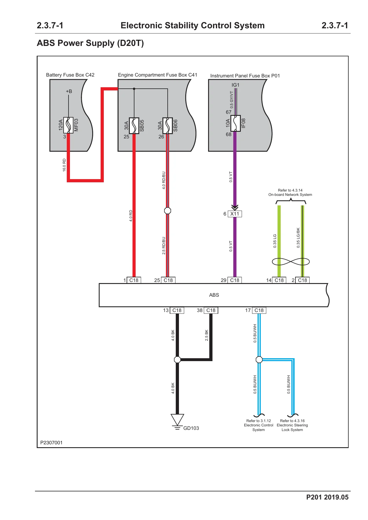
- 2.3.7 Electronic Stability Control System — ABS power, wheel speed sensors, ESCi/rotation angle sensor, ESC and HDC signals for D20T, JE4D25, 4K22T
- 3.1.4 Cooling System — D20T, JE4D25-G5, JE4D25-G6
- 3.1.7 Fuel System — D20T, JE4D25-G5, JE4D25-G6
- 3.1.8 Pre-heating System — D20T, JE4D25-G5, JE4D25-G6
- 3.1.9 Starting System — with and without PEPS on D20T and JE4D25-G5/G6
- 3.1.10 Charging System — D20T, JE4D25
- 3.1.12 Electronic Control System — clutch switches, oxygen sensors, airflow and fuel-filter level, rail pressure, EGR, throttle, accelerator, crank and cam sensors, coolant and intake temperature/pressure, urea/NOx/particulate circuits on JE4D25-G6
- 3.3.4 / 3.3.7 / 3.3.8 / 3.3.9 / 3.3.10 / 3.3.12 — 4K22T cooling, fuel, ignition, starting (MT-G5 and AT-G5), charging, and engine sensors including knock, OCV, canister, boost, and electronic thermostat
- 3.4.1 Automatic Transmission — 4K22T
- 4.1.1 Heating, Ventilation and Air Conditioning — power, 3-state pressure switch, blower, mix/mode/recirculation actuators, compressor for all three engines
- 4.2.1 Airbag Restraint System — collision sensors, driver and passenger bags, side and curtain bags, seat-belt buckles and retractors, occupancy sensor, with and without PEPS
- 4.3.2 Instrument Cluster — fuel level, oil pressure, parking brake, brake fluid level
- 4.3.3 Horn
- 4.3.4 Cigarette Lighter and USB
- 4.3.5 Information and Entertainment System — speakers, cameras, microphone, radio display
- 4.3.6 Lighting System — headlamp, position, turn, brake, fog, reversing, DRL, indoor lamps, PEPS and non-PEPS splits
- 4.3.7 Wiper
- 4.3.8 Power Rearview Mirror and folding circuits
- 4.3.9 Central Door Lock and Body Theft Deterrent, plus 4K22T anti-theft coil
- 4.3.10 Power Window — anti-pinch and non anti-pinch, all four doors, PEPS splits
- 4.3.11 Defroster
- 4.3.12 Parking Assist — 4-sensor and 2-sensor packs
- 4.3.13 Body Control System
- 4.3.14 On-board Network System
- 4.3.15 Keyless Entry — ENGINE START STOP switch and low-frequency antennas
- 4.3.16 Electronic Steering Lock
- 4.3.19 Power Seat (D20T, JE4D25)
- 4.3.20 Seat Heater (D20T/JE4D25)
- 4.3.23 4WD System
- 4.3.24 Panoramic View Monitor
- 4.3.25 Tire Pressure Monitoring
- 6.1.1 Fuse and Relay Information
- 6.1.2 / 6.2.2 Power Supply Distribution for D20T/JE4D25 and 4K22T
- 6.1.3 / 6.2.3 Fuse Details
- 6.1.4 Grounding Distribution
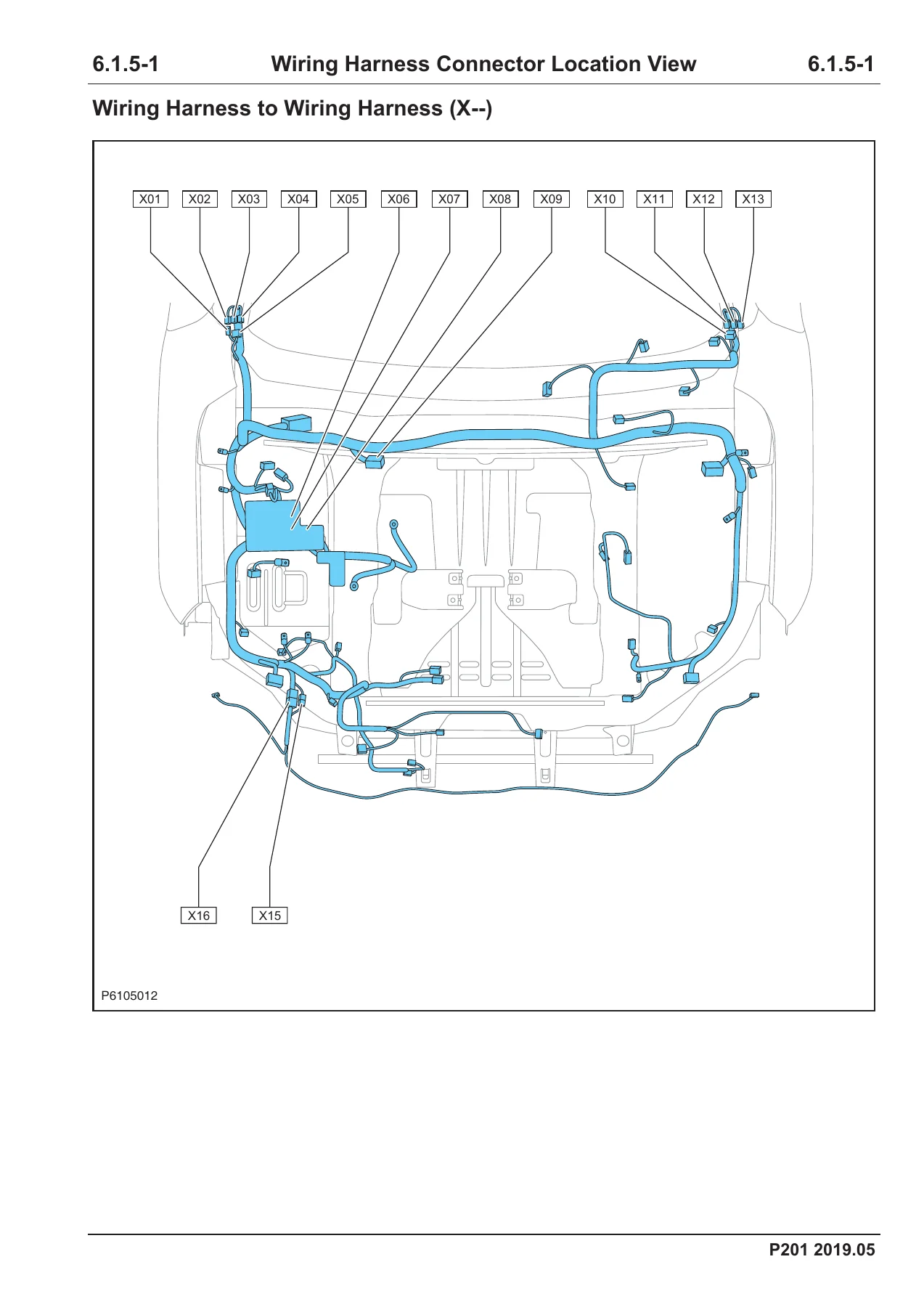
- 6.1.5 Wiring Harness Connector Location View
- 6.1.6 Grounding Location View
- 6.1.7 Wiring Harness Connector Terminal View with pin, wire size/color, and function tables
- 6.1.8 Fuse Box Label — engine compartment, instrument panel, and 5-way boxes
- 6.1.9 Abbreviation List
Taken as a whole, the book is a complete electrical atlas for P201 rather than a mechanical overhaul guide. A technician uses it to identify the correct schematic for the engine and PEPS package on the vehicle, then follows wire color, connector cavity, and fuse ID to the failed device. Location views put X, C, E, P, S, D, and L connectors on the vehicle outline. Terminal views list pin function so a meter can be placed on the right cavity of ECU, BCM, IBCM, ABS, or a door module without piercing insulation.
Engine and Body Variants You Must Match
Diesel-side pages separate D20T from JE4D25-G5 and JE4D25-G6. The G6 set adds urea level/temperature and heater, urea pipe heater, urea glow unit, urea nozzle and pump, NOx sensor, particulate sensor, and resistor jacket circuits that do not appear on G5. Gasoline-side pages for 4K22T add ignition coils, knock sensor, intake and exhaust cam position, boost pressure, electronic throttle, OCV, canister solenoid, electronic thermostat, and separate starting diagrams for MT-G5 and AT-G5 plus an automatic-transmission network page.
Body electrics are drawn twice in most lighting, lock, window, cluster, horn, and HVAC chapters: one sheet for with-PEPS and one for without-PEPS. Keyless entry, ENGINE START STOP, low-frequency antennas, and electronic steering lock sit on the PEPS path. The 4K22T theft chapter also includes the anti-theft controller and anti-theft coil used on without-PEPS vehicles. Parking assist is split into 4-sensor and 2-sensor packs. Power windows are further split into anti-pinch and non anti-pinch left-front, right-front, and rear-door groups. Using the wrong PEPS or anti-pinch sheet will send you to the wrong BCM or IBCM pins.
Power, Fuse, and Ground Reference
Power supply distribution runs across fifteen D20T/JE4D25 sheets and eleven 4K22T sheets, showing how +B, IG1, IG2, and ACC leave the battery fuse box, engine compartment box, instrument panel box, and 5-way box. Fuse details redraw those feeds with ratings such as MF03 120 A, EF18 30 A, EF19 25 A, SB07 40 A, SB10 40 A, EF15 25 A, and IF08 10 A on the ABS IG1 feed. Fuse box label pages give numbered cavity maps for the D20T, JE4D25, and 4K22T engine compartment boxes, the instrument panel box, and each 5-way box, with application text such as main relay 30 A, fuel heater, compressor relay, ECU-A 10 A, brake lamp relay 20 A, and seat heater 10 A.
Grounding distribution lists points GD000 through GD307 and G101/G105 with the devices tied to each point. Location views place those grounds on the body. Combined with the voltage-drop and ground-repair procedure in 1.1.3, those pages support chasing an intermittent lamp, wiper, or module reset caused by a painted or oxidized ring rather than a failed control unit.
What This Manual Lets You Diagnose
Typical jobs supported by the Hunter P201 Wiring Diagrams Manual 2019.05 – D20T JE4D25 4K22T Electrical Circuits PDF include no-start on PEPS and key-switch vehicles, charging and pre-heat faults, injector and rail-pressure control wiring, cooling-fan and compressor clutch feeds, ABS wheel-speed and yaw/rotation-angle circuits, lighting and DRL failures, window and lock motor faults, airbag connector and spiral-cable continuity, HVAC actuator and blower module wiring, 4WD transfer connector S18, panoramic camera feeds, and TPMS module power. Network sheets 4.3.14 show how ESCi, ECU, BCM/IBCM, entertainment head unit, A/C panel, steering lock, and airbag control unit share the on-board network so a communication loss can be isolated to a twisted pair or a terminating module rather than every control unit on the bus.
Get the Circuits and Start Tracing
Correct wire color, fuse ID, and connector cavity stop wasted parts replacement on P201 electrical faults. This manual is the schematic source for those values across D20T, JE4D25, and 4K22T, including PEPS splits. After payment you receive the PDF immediately. Open it on a laptop in the bay, a tablet on the fender, or a phone at the fuse box, and print individual circuit or location pages as needed. No shipping wait.
Reviews
There are no reviews yet.