
★ TRUSTED BY 321,897+ PROFESSIONALS WORLDWIDE
🏒
Trusted Business
Verified & Licensed
πŸ›‘οΈ
Virus Free Files
100% Safe Downloads
πŸ”’
Secure Payment
SSL Protected
⚑
Instant Delivery
Available Immediately
Sale!

2013 Yamaha F200F FL200F Outboard Service Manual 6DA-28197-3S-11

Original price was: $39.95.Current price is: $22.95.

Second Edition factory-issued service manual for the Yamaha F200F and FL200F 200 HP four-stroke outboard. Covers the complete rigging, electrical, fuel, power unit, lower unit, bracket, and maintenance procedures used by Yamaha-trained technicians, including the YDIS diagnostic workflow, VCT and ETV systems, shimming, and full tightening-torque data.

⚑
Instant PDF Download
Available immediately
πŸ’Ύ
Save to Your Device
Download & keep forever
πŸ›‘οΈ
Antivirus Scanned
100% virus-free
🌍
Trusted Worldwide
175,000+ customers

Description

2013 Yamaha F200F FL200F Outboard Service Manual

This is the Second Edition service manual released by Yamaha Motor Co., Ltd. in May 2013 for the F200F and FL200F four-stroke outboard motors. It was written primarily for Yamaha dealers and YTA Bronze-certified marine technicians, and it documents the complete service, repair, and diagnostic workflow for both the standard-rotation F200F and the counter-rotation FL200F.

Every procedure is written around the actual engine that sits on the transom β€” the 2.8-litre, 16-valve, DOHC inline-four with VCT on the intake side, ETV electronic throttle, digital ignition, and a 2-axis balancer. Where a step calls for a Yamaha special service tool, the tool number is given. Where a value must be measured, the tolerance and the measuring condition are given. Where a fastener must be staged, the stages and the angles are shown.

File Details

  • Manual type: Service Manual (dealer / technician level)
  • Brand / manufacturer: Yamaha Motor Co., Ltd.
  • Models covered: F200F, FL200F
  • Document number: 6DA-28197-3S-11
  • Edition: 2nd Edition, May 2013
  • Language: English
  • File format: PDF

Chapters Covered

  • 0 β€” General Information: safety while working, rotating parts, hot parts, electric shock, propeller handling, gasoline handling, ventilation, self-protection, working with a crane, gas torch handling, sealant handling, special service tools, tightening torque, non-reusable parts, disassembly and assembly practice, how to use the manual, abbreviations, lubricant and sealant symbols, special service tool listings.
  • 1 β€” Specification: model feature, model name designation, serial number, model data, dimensions and weight, performance, power unit data, lower unit data, bracket unit data, fuel and oil requirements, battery requirement, PTT fluid requirement, electrical system technical data, ignition timing control, fuel injection control, engine speed control, VCT system, PTT system, charging system, starting system, Y-COP, gauge and sensor data, fuel system technical data, power unit technical data, cylinder head assembly, crankcase assembly, lower unit assembly (regular and counter rotation), bracket unit technical data, PTT system data, specified tightening torques, general tightening torque.
  • 2 β€” Technical Feature and Description: engine ECM components, VCT control, rectifier/regulator/isolator, over-revolution control, knock control, shift-cut control, reverse rotation control, battery removal control, warning control, water detection warning, fail-safe control, YDIS, Y-COP, tilt limiter, power unit system overview, shimless valve lifter, offset cylinder, balancer, flywheel and crankshaft, oil cooler, lower unit, Shift Dampener System (SDS), high-pressure and low-pressure fuel pump control, fuel diagram, lubrication diagram, cooling diagram, intake and exhaust diagram.
  • 3 β€” Rigging Information: outboard motor mounting instructions, crate handling, crate top cover pictographs, uncrating, external dimensions, clamp bracket dimensions, installing the outboard motor, mounting height, rigging grommet mounting and description, installing the battery cable, shift cable, throttle cable, main wire harness, Digital Network Gauge harness, conventional gauge harness, rigging grommet, optional equipment including isolator lead, water pressure sensor, speed sensor, water temperature sensor, speedometer hose, tilt limiter, Y-COP installation, remote control receiver ID registration, battery installation with and without house battery, system diagrams, rigging recommendation, battery cable length, propeller selection and size charts.
  • 4 β€” Troubleshooting: YDIS basic components and function, connecting the communication cable, outboard motor troubleshooting procedure, troubleshooting the power unit using the YDIS, trouble code and checking step tables, troubleshooting the power unit when no trouble code is detected, troubleshooting the PTT unit, troubleshooting the lower unit.
  • 5 β€” Electrical System: port and starboard layout, fuse holder, rear, front, top, bottom cowling, ECM circuit diagram, ECM coupler layout, checking the electrical component, using the YDIS, measuring peak voltage, using the digital tester, engine control unit and component checks (main relay, engine ECM circuit, ETV and TPS, ETV motor relay, APS, cam position sensor, OCV, oil pressure sensor), fuel control unit checks (water detection switch, fuel injector, low and high pressure fuel pumps, high-pressure fuel pump relay, vapor shut-off valve), charging unit checks (lighting coil, rectifier/regulator/isolator), ignition unit checks (ignition spark, ignition coil, pulser coil, intake air temperature sensor, intake air pressure sensor, engine temperature sensor, thermo switch, knock sensor, shift cut-off switch, shift position switch, engine shut-off switch), starting unit checks (starter relay, engine start switch), Y-COP checks, starter motor removal, disassembly, inspection, assembly and installation, Digital Network Gauge sensor checks, PTT system checks.
  • 6 β€” Fuel System: hose routing (fuel hose, pressure regulator hose, vapor gas hose, blowby hose, cooling water hose), reducing fuel pressure, disconnecting the quick connector, measuring fuel pressure, checking the pressure regulator, fuel filter (removal, checking, disassembly, element, cup assembly, primer pump, assembly and installation), low-pressure fuel pump (draining, removal, checking, installation), canister and vapor shut-off valve, ETV, fuel injector, intake manifold, vapor separator and APS, vapor separator and high-pressure fuel pump.
  • 7 β€” Power Unit: compression pressure, oil pressure, pulser coil air gap, valve clearance checking and adjustment, power unit assembly for L-transom and X-transom models, removal and installation of the power unit, flywheel magneto, timing belt, starter motor, engine ECM, fuse box, rectifier/regulator/isolator, ignition coil and spark plug, wire harness, camshaft, cylinder head, exhaust cover, oil cooler, cylinder block, crankcase, piston and connecting rod, crankshaft and bearing selection tables.
  • 8 β€” Lower Unit: regular rotation model and counter rotation model sections covering removal, propeller disassembly and assembly including Shift Damper System propellers, water pump and shift rod, propeller shaft housing, drive shaft and lower case, shimming workflow and check sheets, pinion shim (T3) selection, forward gear shim (T1) selection, reverse gear shim (T2) selection, propeller shaft shim (T4) selection, backlash measurement procedures, lower unit air leakage checks and installation.
  • 9 β€” Bracket Unit: shift rod and shift bracket, PTT switch and cowling lock lever, bottom cowling, upper case and mounts for L-transom and X-transom models, oil pan and exhaust manifold, steering arm, clamp bracket and swivel bracket, PTT unit, PTT motor, PTT gear pump, PTT cylinder including tilt ram and trim ram.
  • 10 β€” Maintenance: outline, maintenance interval chart 1 and chart 2, predelivery check, checking the battery, cooling water pilot hole, engine oil level, main switch/stop switch, fuel line, gear oil level, shift link/shift cable and throttle link/throttle cable, outboard motor mounting height, power trim and tilt unit, steering system, test run, break-in schedule, after test run, general periodic maintenance covering anodes, battery, cooling water inlet and pilot hole, engine idle speed and noise, changing engine oil by oil changer or drain bolt, replacing oil filter, exhaust guide and manifold, fuel filter, fuel pump, fuel and engine oil leakage, gear oil change, gear oil level, OCV filter, greasing points, PCV, propeller and propeller nut and cotter pin, PTT fluid level, PTT operation, shift link and shift cable adjustment, spark plug, timing belt, thermostat, throttle link and cable, cowling lock lever, valve clearance, impeller and water pump housing.
  • Index and Appendix A: alphabetical index, wiring diagram with how-to-use guide, engine control unit, fuel unit and ignition unit, charging unit, starting unit, PTT unit, control unit, pinion shim selection table, forward gear shim selection chart, reverse gear shim selection chart, counter-rotation shim selection tables and charts.

Across these chapters the manual hands a technician the complete factory service library for one specific outboard: how the 2.8-litre powerhead is built, how the VCT and ETV electronics are wired and tested, how the fuel injection and vapor separator systems are plumbed and diagnosed, how the lower unit is shimmed to the correct backlash, how the bracket and PTT unit are rebuilt, and what every specification and torque figure should be when the job is done. The troubleshooting chapter and the YDIS sections are the diagnostic backbone of the book, and the shimming workflow in chapter 8 is what separates a rebuilt lower unit that runs quietly for years from one that whines itself apart.

Who This Manual Is For

If you work on the F200F or FL200F β€” as a marine mechanic, a serious owner, or a shop supporting a fleet of Yamaha outboards β€” this is the document that tells you how the factory wants each job performed. It matters most where the stakes are high: valve clearance adjustment on a shimless-lifter head, timing belt installation, camshaft and VCT assembly, crankshaft bearing selection, lower unit shimming, and PTT hydraulic checks. Those procedures require exact figures and exact sequencing, and that is what this book provides. It is also the manual you want when a trouble code appears and you need the checking steps that correspond to the code, rather than guessing at a sensor.

What You Can Do With It

  • Diagnose engine faults through the YDIS workflow and the trouble-code checking tables.
  • Service the VCT, ETV, digital ignition, and electronic fuel injection systems.
  • Adjust valve clearances using the shimless valve lifter selection method.
  • Remove, inspect, and reinstall the timing belt and camshafts.
  • Rebuild the lower unit on the bench and shim the pinion, forward gear, and reverse gear back to specification.
  • Repair the PTT unit, PTT motor, gear pump, tilt ram, and trim ram, and bleed the system correctly.
  • Rig a new or replacement outboard, install the shift and throttle cables, and set up the Y-COP or tilt limiter.
  • Run the full maintenance schedule, from engine oil and gear oil changes to greasing points and anode inspection.

Complete PDF Bookmark Tree

Complete Bookmarks

The complete bookmarks in the β€œ2013 Yamaha F200F FL200F Outboard Service Manual 6DA-28197-3S-11” are as follows:

Contentsp. 3
General informationp. 5
!Safety while workingp. 6
Rotating partp. 6
Hot partp. 6
Electric shockp. 6
Propellerp. 6
Handling of gasolinep. 6
Ventilationp. 6
Self-protectionp. 7
Working with cranep. 7
Handling of gas torchp. 7
Part, lubricant, and sealantp. 7
Handling of sealantp. 8
Special service toolp. 8
Tightening torquep. 8
Non-reusable partp. 8
Disassembly and assemblyp. 8
How to use this manualp. 9
Manual formatp. 9
Abbreviationp. 10
Lubricant, sealant, and thread locking agentp. 11
Symbolp. 11
Special service toolp. 13
Specificationp. 24
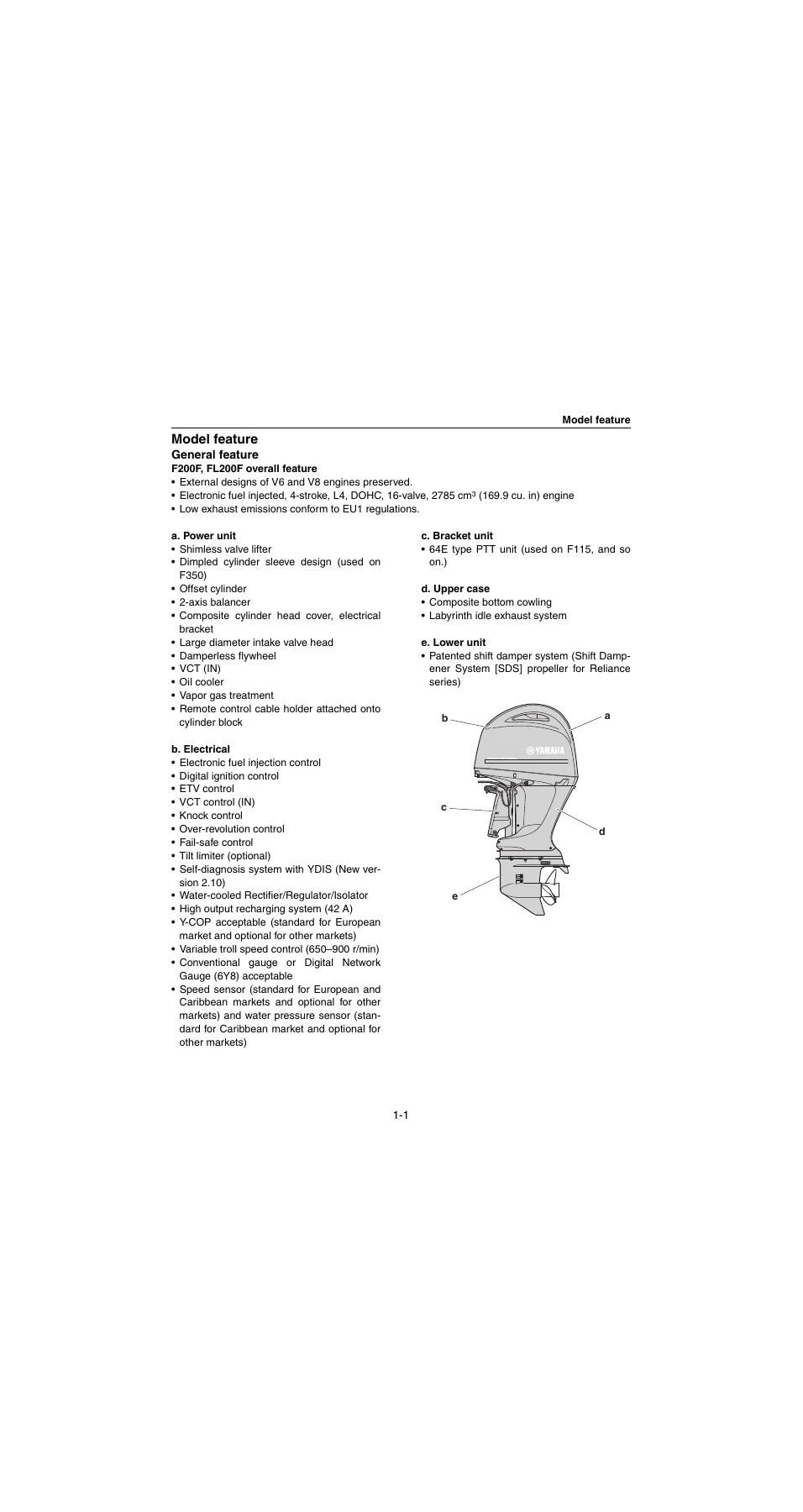
Model featurep. 26
General featurep. 26
Model name designationp. 27
Serial numberp. 28
Model datap. 29
Dimension and weightp. 29
Performancep. 29
Power unitp. 29
Lower unitp. 29
Bracket unitp. 30
Fuel and oil requirementp. 30
Battery requirementp. 30
PTT fluid requirementp. 30
Electrical system technical datap. 31
Ignition timing control systemp. 31
Fuel injection control systemp. 31
Engine speed control systemp. 32
VCT systemp. 32
PTT systemp. 32
Charging systemp. 32
Starting systemp. 33
Y-COPp. 33
Gauge/sensorp. 33
Fuel system technical datap. 34
Fuel systemp. 34
Power unit technical datap. 35
Power unitp. 35
Cylinder head assemblyp. 35
Crankcase assemblyp. 36
Lower unit technical datap. 38
Lower unit assembly (regular rotation model)p. 38
Lower unit assembly (counter rotation model)p. 38
Bracket unit technical datap. 39
PTT systemp. 39
Specified tightening torquep. 40
Rigging informationp. 40
Electrical systemp. 40
Fuel systemp. 40
Power unitp. 41
Lower unit (regular rotation model)p. 44
Lower unit (counter rotation model)p. 44
Bracket unitp. 45
PTT unitp. 46
General tightening torquep. 47
Technical feature and descriptionp. 48
Electronic control systemp. 50
Engine ECM componentsp. 52
VCT controlp. 54
Rectifier/Regulator/Isolatorp. 55
Over-revolution controlp. 55
Knock controlp. 55
Shift-cut controlp. 56
Reverse rotation controlp. 56
Battery removal controlp. 56
Warning controlp. 56
Water detection warningp. 57
Fail-safe controlp. 57
YDISp. 58
Additional featuresp. 59
Y-COP (standard for European market and optional for Oceanian market)p. 59
Tilt limiter (Optional)p. 60
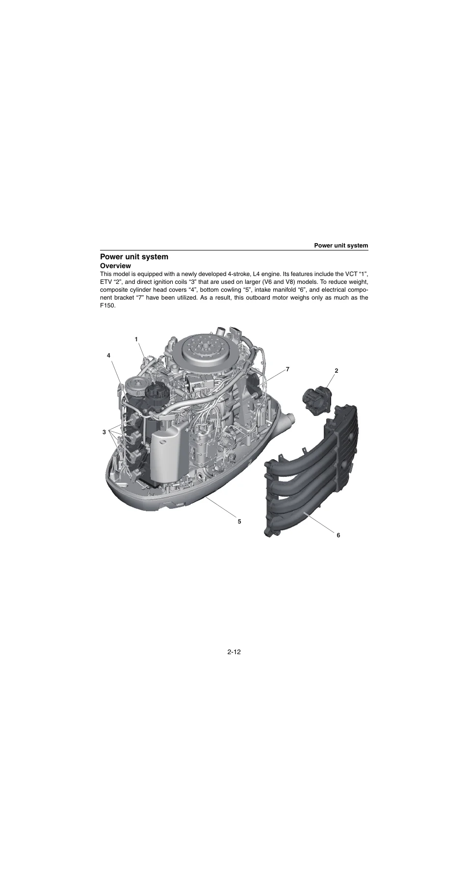
Power unit systemp. 61
Overviewp. 61
Shimless valve lifterp. 62
Offset cylinderp. 63
Balancerp. 64
Flywheel and crankshaftp. 65
Oil coolerp. 65
Lower unitp. 66
Shift Dampener System (SDS)p. 67
Fuel systemp. 67
High-pressure fuel pump controlp. 67
Low-pressure fuel pump controlp. 68
Fuel diagramp. 68
Lubrication systemp. 70
Lubrication diagramp. 70
Cooling systemp. 72
Cooling diagramp. 72
Intake and exhaust systemp. 74
Intake and exhaust diagramp. 74
Rigging informationp. 76
Important reminder on riggingp. 78
Outboard motor mounting instructionsp. 78
Crate handlingp. 79
Crate top cover pictograph descriptionp. 79
Uncratingp. 80
Uncrating procedurep. 80
External dimensionsp. 82
Clamp bracket dimensionsp. 83
Outboard motor mountingp. 84
Installing the outboard motorp. 84
Outboard motor mounting heightp. 86
Rigging grommet mountingp. 86
Rigging grommet descriptionp. 86
Installing the battery cablep. 86
Installing the shift cablep. 87
Installing the throttle cablep. 88
Installing the main wire harnessp. 89
Installing the Digital Network Gauge harnessp. 89
Installing the conventional gauge harnessp. 89
Installing the rigging grommetp. 90
Optional equipmentp. 90
Installing the isolator leadp. 90
Installing the water pressure sensor (Digital Network Gauge)p. 91
Installing the speed sensor (Digital Network Gauge)p. 92
Installing the water temperature sensor (conventional gauge)p. 93
Installing the water pressure sensor (conventional gauge)p. 94
Connecting the speedometer hose (conventional gauge)p. 95
Installing the tilt limiterp. 95
Setting the tilt limiterp. 98
Deactivating the tilt limiterp. 99
Y-COP (standard for European market and optional for other markets)p. 100
Installing Y-COPp. 100
Registering the remote control receiver ID to the ECMp. 100
Battery installationp. 102
Battery wiring without house batteryp. 102
Battery wiring with house batteryp. 105
System diagramp. 110
Single engine application (Digital Network Gauge)p. 110
Single engine application (conventional gauge)p. 112
Twin engine application (Digital Network Gauge)p. 114
Twin engine application (conventional gauge)p. 118
Rigging recommendationp. 120
Battery cable lengthp. 120
Extension length recommendation for battery cablep. 120
Propeller selectionp. 122
Propeller sizep. 122
Selectionp. 122
Troubleshootingp. 125
YDISp. 126
Basic componentsp. 126
Functionp. 127
Connecting the communication cablep. 132
Outboard motor troubleshootingp. 133
Troubleshooting procedurep. 133
Troubleshooting the power unit using the YDISp. 133
Trouble code and checking stepp. 135
Troubleshooting the power unit (trouble code not detected)p. 140
Troubleshooting the PTT unitp. 145
Troubleshooting the lower unitp. 146
Electrical systemp. 147
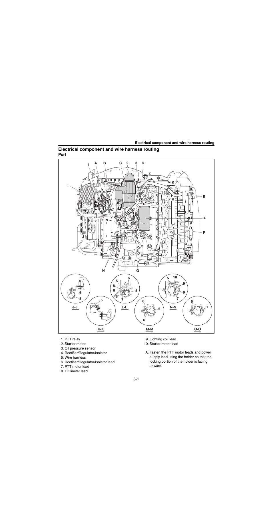
Electrical component and wire harness routingp. 150
Portp. 150
Starboardp. 153
Fuse holderp. 156
Rearp. 157
Frontp. 158
Topp. 159
Bottom cowlingp. 161
ECM circuit diagramp. 163
ECM coupler layoutp. 166
Checking the electrical componentp. 168
Using the YDISp. 168
Measuring the peak voltagep. 168
Using the digital testerp. 168
Engine control unit and componentp. 169
Checking the main relayp. 169
Checking the engine ECM circuitp. 170
Checking the ETV and TPSp. 170
Checking the ETV motor relayp. 171
Checking the APSp. 171
Checking the cam position sensorp. 172
Checking the OCVp. 174
Checking the oil pressure sensorp. 174
Fuel control unit and componentp. 175
Checking the water detection switchp. 175
Checking the fuel injectorp. 176
Checking the low-pressure fuel pump and high-pressure fuel pumpp. 176
Checking the high-pressure fuel pump relayp. 177
Checking the vapor shut-off valvep. 178
Charging unit and componentp. 178
Checking the lighting coil (stator assembly)p. 178
Checking the Rectifier/Regulator/ Isolatorp. 179
Ignition unit and componentp. 181
Checking the ignition sparkp. 181
Checking the ignition coilp. 182
Checking the pulser coilp. 182
Checking the intake air temperature sensorp. 183
Checking the intake air pressure sensorp. 183
Checking the engine temperature sensorp. 183
Checking the thermo switchp. 184
Checking the knock sensorp. 184
Checking the shift cut-off switchp. 185
Checking the shift position switchp. 185
Checking the engine shut-off switchp. 186
Starting unit and componentp. 186
Checking the starter relayp. 186
Checking the engine start switchp. 187
Y-COP (standard for European market and optional for other markets)p. 188
Checking Y-COPp. 189
Checking the buzzerp. 189
Checking the Y-COP main wire harnessp. 189
Checking the button cell batteryp. 190
Starter motorp. 192
Removing the starter motorp. 194
Disassembling the starter motorp. 194
Checking the starter motor pinionp. 195
Checking the armature (starter motor)p. 196
Checking the brush holderp. 196
Assembling the starter motorp. 197
Installing the starter motorp. 199
Digital Network Gauge sensorp. 199
Checking the water pressure sensorp. 199
Checking the speed sensorp. 199
PTT systemp. 200
Checking the PTT relayp. 200
Checking the PTT switch (on bottom cowling)p. 201
Checking the trim sensorp. 201
Checking the tilt limiterp. 202
Fuel systemp. 204
Hose routingp. 206
Fuel hosep. 206
Pressure regulator hose, vapor gas hose, and blowby hosep. 207
Cooling water hosep. 209
Fuel systemp. 211
Reducing the fuel pressurep. 211
Disconnecting the quick connectorp. 211
Measuring the fuel pressurep. 211
Checking the pressure regulatorp. 212
Fuel filterp. 214
Removing the fuel filter assemblyp. 215
Checking the fuel filter assemblyp. 215
Disassembling the fuel filter assemblyp. 216
Checking the fuel filter elementp. 216
Checking the fuel cup assemblyp. 216
Checking the primer pumpp. 216
Assembling the fuel filter assemblyp. 216
Installing the fuel filter assemblyp. 216
Low-pressure fuel pumpp. 218
Draining the fuelp. 219
Removing the low-pressure fuel pumpp. 219
Checking the low-pressure fuel pumpp. 220
Installing the low-pressure fuel pumpp. 220
Canister and vapor shut-off valvep. 222
Removing the canister and vapor shut-off valvep. 223
Checking the canisterp. 223
Checking the vapor shut-off valvep. 223
Installing the vapor shut-off valve and canisterp. 224
ETVp. 225
Removing the ETVp. 226
Checking the ETVp. 226
Installing the ETVp. 226
Fuel injectorp. 228
Removing the fuel injectorp. 229
Checking the fuel rail and fuel injectorp. 230
Installing the fuel injectorp. 230
Intake manifoldp. 232
Removing the intake manifoldp. 233
Checking the intake manifoldp. 233
Checking the intake air pressure/ temperature sensorp. 233
Installing the intake manifoldp. 234
Vapor separator and APSp. 236
Removing the vapor separatorp. 238
Removing the APSp. 239
Checking the canister check valvep. 239
Checking the APSp. 240
Installing the APSp. 240
Installing the vapor separatorp. 240
Vapor separator and high-pressure fuel pumpp. 243
Disassembling the vapor separatorp. 245
Checking the high-pressure fuel pumpp. 246
Checking the vapor separatorp. 246
Checking the check valvep. 246
Assembling the vapor separatorp. 247
Power unitp. 249
Power unit (check and adjustment)p. 252
Checking the compression pressurep. 252
Checking the oil pressurep. 252
Checking the pulser coil air gapp. 252
Checking the valve clearancep. 253
Adjusting the valve clearancep. 255
Power unit assembly (L-transom model)p. 257
Power unit assembly (X-transom model)p. 259
Removing the power unitp. 261
Installing the power unitp. 264
Flywheel magnetop. 268
Removing the flywheel magnetop. 269
Installing the flywheel magnetop. 270
Timing beltp. 272
Removing the timing beltp. 273
Checking the timing beltp. 273
Installing the timing beltp. 273
Starter motorp. 276
Removing the starter motorp. 278
Installing the starter motorp. 278
Engine ECMp. 280
Fuse boxp. 281
Rectifier/Regulator/Isolatorp. 282
Removing the Rectifier/Regulator/ Isolatorp. 283
Installing the Rectifier/Regulator/ Isolatorp. 283
Ignition coil and spark plugp. 285
Checking the spark plugp. 286
Wire harnessp. 287
Removing the wire harnessp. 289
Installing the wire harnessp. 290
Camshaftp. 293
Removing the driven sprocket and camshaftp. 295
Checking the sprocketp. 296
Checking the valve lifterp. 296
Checking the camshaftp. 297
Checking the camshaft journal oil clearancep. 297
Installing the camshaft and driven sprocketp. 299
Cylinder headp. 303
Removing the cylinder headp. 306
Disassembling the cylinder headp. 306
Checking the cylinder headp. 307
Checking the cylinder head boltp. 307
Checking the valve springp. 307
Checking the valvep. 308
Checking the valve guidep. 308
Replacing the valve guidep. 309
Checking the valve seatp. 309
Refacing the valve seatp. 310
Checking the cylinder head and cylinder block anodep. 312
Assembling the cylinder headp. 312
Installing the cylinder headp. 313
Exhaust coverp. 315
Removing the exhaust coverp. 318
Checking the PCVp. 319
Checking the thermostatp. 319
Checking the exhaust cover anodep. 319
Installing the exhaust coverp. 319
Oil coolerp. 322
Removing the crankcase coverp. 325
Checking the crankcase cover anodep. 325
Installing the crankcase coverp. 325
Cylinder blockp. 327
Removing the oil pump assemblyp. 330
Removing the oil filter bracketp. 330
Removing the balancer assemblyp. 330
Disassembling the oil pumpp. 330
Checking the oil pumpp. 331
Assembling the oil pumpp. 331
Installing the oil pump assemblyp. 332
Checking the cylinder block anodep. 332
Installing the balancer assemblyp. 332
Installing the oil filter bracketp. 333
Crankcasep. 335
Disassembling the cylinder blockp. 337
Checking the piston diameterp. 338
Checking the cylinder borep. 338
Checking the piston clearancep. 338
Checking the piston ringp. 339
Checking the piston ring end gapp. 339
Checking the piston ring groovep. 339
Checking the piston ring side clearancep. 340
Checking the piston pin boss inside diameterp. 340
Checking the piston pin diameterp. 340
Checking the connecting rod small end inside diameter and big end inside diameterp. 341
Checking the connecting rod big end side clearancep. 341
Checking the crankshaftp. 341
Checking the big end oil clearancep. 342
Selecting the crankshaft pin bearingp. 343
Crankshaft pin bearing selection tablep. 345
Checking the journal oil clearancep. 346
Selecting the crankshaft journal bearingp. 347
Crankshaft journal bearing selection tablep. 349
Assembling the cylinder blockp. 350
Lower unitp. 355
Lower unit (regular rotation model)p. 358
Removing the lower unitp. 360
Disassembling the propeller (Shift Damper System [SDS] propeller)p. 360
Checking the propellerp. 360
Checking the lower unit anodep. 360
Assembling the propeller (Shift Damper System [SDS] propeller)p. 361
Water pump and shift rod (regular rotation model)p. 363
Removing the water pump and shift rodp. 365
Disassembling the water pump housingp. 365
Checking the water pump and shift rodp. 365
Assembling the water pump housingp. 366
Propeller shaft housing (regular rotation model)p. 367
Removing the propeller shaft housing assemblyp. 369
Disassembling the propeller shaft assemblyp. 369
Disassembling the propeller shaft housing assemblyp. 370
Checking the propeller shaftp. 370
Checking the dog clutchp. 370
Checking the propeller shaft housingp. 370
Checking the reverse gearp. 370
Assembling the propeller shaft assemblyp. 371
Assembling the propeller shaft housing assemblyp. 371
Drive shaft and lower case (regular rotation model)p. 373
Removing the drive shaftp. 375
Removing the forward gearp. 375
Disassembling the drive shaft housingp. 375
Disassembling the forward gearp. 375
Disassembling the lower casep. 376
Checking the pinionp. 376
Checking the forward gearp. 376
Checking the drive shaftp. 376
Checking the lower casep. 377
Assembling the forward gearp. 377
Assembling the drive shaft housingp. 377
Assembling the lower casep. 378
Installing the forward gearp. 379
Installing the drive shaftp. 379
Installing the propeller shaft housing assemblyp. 380
Installing the shift rodp. 381
Installing the water pumpp. 381
Checking the lower unit for air leakagep. 383
Installing the lower unitp. 383
Shimming (regular rotation model)p. 385
Shimming workflowp. 385
Shimming check sheetp. 386
Measuring the forward gear backlash and reverse gear backlash before disassemblyp. 388
Shimming procedurep. 391
Shim locationp. 391
Selecting the pinion shim (T3)p. 392
Measuring the forward gear backlashp. 394
Adjusting the forward gear shim thickness (T1)p. 395
Measuring the reverse gear backlashp. 396
Adjusting the reverse gear shim thickness (T2)p. 396
Lower unit (counter rotation model)p. 398
Removing the lower unitp. 400
Disassembling the propeller (Shift Damper System [SDS] propeller)p. 400
Checking the propellerp. 400
Checking the lower unit anodep. 400
Assembling the propeller (Shift Damper System [SDS] propeller)p. 400
Water pump and shift rod (counter rotation model)p. 401
Removing the water pump and shift rodp. 403
Disassembling the water pump housingp. 403
Checking the water pump and shift rodp. 403
Assembling the water pump housingp. 403
Propeller shaft housing (counter rotation model)p. 404
Removing the propeller shaft housing assemblyp. 406
Disassembling the propeller shaft housing assemblyp. 406
Disassembling the forward gearp. 407
Checking the propeller shaftp. 407
Checking the dog clutchp. 407
Checking the propeller shaft housingp. 407
Checking the forward gearp. 407
Assembling the propeller shaft housing assembly and forward gearp. 407
Drive shaft and lower case (counter rotation model)p. 410
Removing the drive shaftp. 412
Removing the reverse gearp. 412
Disassembling the drive shaft housingp. 412
Disassembling the reverse gearp. 412
Disassembling the lower casep. 412
Checking the pinionp. 413
Checking the reverse gearp. 413
Checking the drive shaftp. 413
Checking the lower casep. 413
Assembling the reverse gearp. 413
Assembling the lower casep. 413
Assembling the drive shaft housingp. 414
Installing the reverse gearp. 414
Installing the drive shaftp. 414
Installing the propeller shaft housing assemblyp. 414
Installing the shift rodp. 414
Installing the water pumpp. 415
Checking the lower unit for air leakagep. 415
Installing the lower unitp. 415
Shimming (counter rotation model)p. 416
Shimming workflowp. 416
Shimming check sheetp. 417
Measuring the forward gear backlash and reverse gear backlash before disassemblyp. 419
Shimming procedurep. 422
Shim locationp. 422
Selecting the pinion shim (T3)p. 423
Selecting the propeller shaft shim (T4)p. 423
Measuring the reverse gear backlashp. 424
Adjusting the reverse gear shim thickness (T1)p. 424
Measuring the forward gear backlashp. 426
Adjusting the forward gear shim thickness (T2)p. 426
Bracket unitp. 429
Shift rod and shift bracketp. 432
Removing the shift rod and shift bracketp. 434
Disassembling the shift bracketp. 434
Assembling the shift bracketp. 434
Installing the shift rod and shift bracketp. 435
PTT switch and cowling lock leverp. 437
Removing the PTT switchp. 439
Removing the cowling lock leverp. 439
Removing the flushing hosep. 439
Installing the flushing hosep. 439
Installing the cowling lock leverp. 440
Installing the PTT switchp. 440
Bottom cowlingp. 441
Upper case and mounts (L-transom model)p. 442
Removing the upper casep. 444
Installing the upper casep. 444
Upper case (L-transom model)p. 446
Disassembling the upper casep. 448
Checking the drive shaft bushingp. 448
Assembling the upper casep. 448
Oil pan and exhaust manifold (L-transom model)p. 450
Disassembling the oil pan and exhaust manifoldp. 452
Checking the oil pan and exhaust manifoldp. 452
Checking the oil strainerp. 452
Assembling the oil pan and exhaust manifoldp. 452
Steering arm (L-transom model)p. 454
Removing the steering armp. 455
Installing the steering armp. 455
Upper case and mounts (X-transom model)p. 457
Removing the upper casep. 459
Installing the upper casep. 459
Upper case (X-transom model)p. 461
Disassembling the upper casep. 463
Checking the drive shaft bushingp. 463
Assembling the upper casep. 463
Oil pan and exhaust manifold (X-transom model)p. 465
Disassembling the oil pan and exhaust manifoldp. 467
Checking the oil pan and exhaust manifoldp. 467
Checking the oil strainerp. 467
Assembling the oil pan and exhaust manifoldp. 467
Steering arm (X-transom model)p. 469
Removing the steering armp. 470
Installing the steering armp. 470
Clamp bracket and swivel bracketp. 472
Removing the clamp bracketp. 475
Checking the clamp bracket anodep. 475
Installing the clamp bracketp. 476
Adjusting the trim sensor camp. 477
PTT unitp. 478
Removing the PTT unitp. 479
Checking the hydraulic pressurep. 479
Bleeding the PTT unitp. 482
Installing the PTT unitp. 483
PTT motorp. 485
Removing the reservoirp. 487
Removing the PTT motorp. 487
Disassembling the PTT motorp. 487
Checking the armature (PTT motor)p. 488
Checking the brushp. 488
Checking the reservoirp. 489
Assembling the PTT motorp. 489
Installing the reservoirp. 490
Installing the PTT motorp. 490
PTT gear pumpp. 492
Disassembling the gear pump assemblyp. 494
Checking the gear pumpp. 495
Checking the gear pump housingp. 495
Checking the filterp. 495
Assembling the gear pump assemblyp. 495
PTT cylinderp. 497
Removing the tilt ram and trim ramp. 499
Removing the filterp. 499
Checking the filterp. 500
Installing the filterp. 500
Disassembling the tilt ramp. 500
Checking the tilt cylinder and trim cylinderp. 500
Checking the absorber valvep. 501
Assembling the tilt ramp. 501
Assembling the trim ramp. 502
Installing the trim ramp. 502
Installing the tilt ramp. 503
Maintenancep. 506
Outlinep. 508
Maintenance interval chart 1p. 508
Maintenance interval chart 2p. 510
Predelivery checkp. 511
Checking the batteryp. 511
Checking the cooling water pilot holep. 512
Checking the engine oil levelp. 512
Checking the main switch/stop switchp. 512
Checking the fuel linep. 513
Checking the gear oil levelp. 513
Checking the shift link/shift cable and throttle link/throttle cablep. 513
Checking the outboard motor mounting heightp. 513
Checking the power trim and tilt unitp. 514
Checking the steering systemp. 514
Checking the throttle cable and shift cablep. 514
Test runp. 514
Break-inp. 515
After test runp. 515
General periodic maintenancep. 515
Checking the anodep. 515
Checking the batteryp. 515
Checking the cooling water inletp. 515
Checking the cooling water pilot holep. 516
Checking the engine idle speed/ noisep. 516
Changing the engine oil using an oil changerp. 516
Changing the engine oil by removing the drain boltp. 517
Checking the engine oil levelp. 519
Replacing the oil filterp. 519
Checking the exhaust guide/exhaust manifoldp. 520
Checking the main switch/stop switchp. 520
Checking the fuel filterp. 520
Checking the fuel pumpp. 520
Checking for fuel/engine oil leakagep. 520
Changing the gear oilp. 520
Checking the gear oil levelp. 521
Replacing the OCV filterp. 521
Greasing pointsp. 521
Checking the PCVp. 523
Checking the propeller/propeller nut/ cotter pinp. 523
Checking the PTT fluid levelp. 523
Checking the power trim and tilt unit operationp. 523
Adjusting the shift link/shift cablep. 524
Checking the spark plugp. 524
Checking the timing beltp. 524
Replacing the timing beltp. 524
Checking the thermostatp. 524
Adjusting the throttle link/throttle cablep. 524
Checking the cowling lock leverp. 524
Checking the valve clearancep. 524
Checking the impeller/water pump housingp. 524
Indexp. 525
Appendixp. 532
Wiring diagramp. 533
How to use the wiring diagramp. 533
Engine control unitp. 538
Fuel unit and ignition unitp. 539
Charging unit, starting unit, and PTT unitp. 540
Control unitp. 541
Shim selection table and chart (regular rotation model)p. 542
Pinion shim (T3) selection tablep. 542
Forward gear shim (T1) selection chart (regular rotation model)p. 543
Reverse gear shim (T2) selection chart (regular rotation model)p. 543
Shim selection table and chart (counter rotation model)p. 544
Pinion shim (T3) selection tablep. 544
Propeller shaft shim (T4) selection tablep. 544
Forward gear shim (T2) selection chart (counter rotation model)p. 545
Reverse gear shim (T1) selection chart (counter rotation model)p. 545


IMAGES PREVIEW

2013 Yamaha F200F FL200F Outboard Service Manual 6DA-28197-3S-11 β€” PDF page 26 preview
2013 Yamaha F200F FL200F Outboard Service Manual 6DA-28197-3S-11 β€” PDF page 61 preview
2013 Yamaha F200F FL200F Outboard Service Manual 6DA-28197-3S-11 β€” PDF page 150 preview

The manual is delivered as a downloadable PDF that opens on any phone, tablet, laptop, or desktop, and every page can be printed for the workshop bench. There is no shipping and no waiting β€” the file is available immediately after purchase, and because it is a digital document you can keep it on every device you use and print only the pages you need for the job in front of you.
Reviews

There are no reviews yet.

Be the first to review “2013 Yamaha F200F FL200F Outboard Service Manual 6DA-28197-3S-11”

What Our Customers Say

β˜…β˜…β˜…β˜…β˜… Live reviews from customers
Loading customer reviews...
0
    0
    Your Cart
    Your cart is emptyReturn to Shop
    πŸ›’
    Recently Purchased
    πŸ•’ verified order