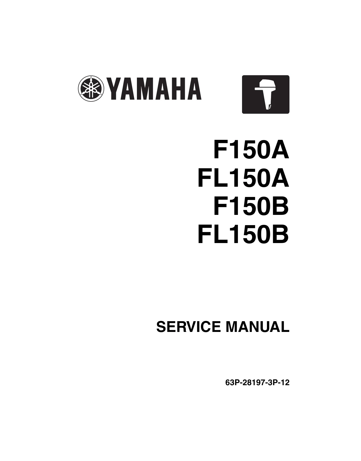
Yamaha F150A FL150A F150B FL150B 150HP Outboard Service Manual PDF
$49.95 Original price was: $49.95.$29.95Current price is: $29.95.
Complete 493-page Yamaha service manual for F150A, FL150A, F150B and FL150B 150 HP outboard motors. Covers specifications, YDIS diagnostics, electrical and fuel systems, power unit repair, lower unit overhaul, PTT and bracket service, rigging, troubleshooting, torque data and scheduled maintenance.
Description
Yamaha F150A FL150A F150B FL150B 150HP Outboard Service Manual PDF
The Yamaha F150A FL150A F150B FL150B 150HP Outboard Service Manual PDF is a detailed 493-page service reference for the F150A, FL150A, F150B and FL150B outboard motor families. Yamaha states that this manual was prepared primarily for Yamaha dealers and trained mechanics performing maintenance procedures and repairs, and its coverage reflects that technical focus: specifications, system descriptions, diagnostics, adjustment data, electrical testing, mechanical disassembly and assembly, rigging, troubleshooting and periodic maintenance are all developed in depth.
The manual distinguishes regular-rotation and counter-rotation applications where procedures or specifications differ. It also identifies applicable model codes and starting serial numbers, provides extensive component illustrations and exploded views, and gives service measurements, clearances, pressures, electrical values and tightening torques throughout the repair procedures.
File Details
- Manual type: Service Manual
- Brand: Yamaha
- Models: F150A, FL150A, F150B, FL150B
- Document number: 63P-28197-3P-12
- Edition: 1st Edition, October 2011
- Language: English
- Pages: 493
- File format: PDF
Model and Serial Number Coverage
The Yamaha F150A FL150A F150B FL150B service manual identifies four model designations with their approved model codes and starting serial numbers. This information is useful when confirming that the service data applies to the outboard being repaired or inspected.
- F150AET: approved model code 63P, starting serial number 1106291-
- FL150AET: approved model code 64P, starting serial number 1013389-
- F150BET: approved model code 6BM, starting serial number 1001267-
- FL150BET: approved model code 6BN, starting serial number 1000213-
Engine and Service Data
The specification section establishes the mechanical baseline used throughout the manual. The covered power unit is a 4-stroke, inline 4-cylinder DOHC design with 16 valves and 2670.0 cm3 (162.9 cu. in) displacement. Bore and stroke are listed as 94.0 Γ 96.2 mm (3.70 Γ 3.79 in), compression ratio as 9.00 : 1, and the fuel system as electronic fuel injection. The manual specifies TCI ignition, water cooling, wet-sump lubrication, electric starting and a maximum generator output of 36 A.
Performance and service data are separated where the A and B model generations differ. F150AET and FL150AET are specified at 110.3 kW at 5500 r/min (150 HP at 5500 r/min) with a full-throttle operating range of 5000-6000 r/min. F150BET and FL150BET are specified at 110.3 kW at 5000 r/min (1150 HP at 5000 r/min) with a 4500-5500 r/min full-throttle range. Engine idle speed is specified at 650-750 r/min.
The lower unit uses F-N-R gear positions, a 2.00 (28/14) gear ratio, spiral bevel gears and a dog clutch. The manual distinguishes clockwise F150 models from counter-clockwise FL150 models and supplies separate lower-unit data and overhaul procedures where required.
IMAGES PREVIEW
Diagnostics, Measurements and Repair Procedures
A major part of this Yamaha F150A FL150A F150B FL150B 150HP Outboard Service Manual PDF is devoted to systematic diagnosis rather than component replacement by guesswork. YDIS version 2.00 coverage includes diagnosis codes, diagnosis records, engine operating hours by RPM, real-time engine monitoring, digital and graph displays, stationary and active tests, data logging, CAN information, communication lists and bus statistics. The troubleshooting chapter links detected trouble codes to specific checking steps and also covers symptoms where no trouble code is detected.
Electrical procedures provide test points and reference values for the ECM circuit, TPS, ISC valve, oil-pressure sensor, water-detection switch, fuel injectors, high-pressure fuel pump, vapor shut-off valve, lighting coil, Rectifier Regulator, ignition coils, pulser coils, temperature and pressure sensors, shift switches, starter circuits, Y-COP components and PTT electrical components. Wiring-harness routing illustrations, ECM terminal assignments and system diagrams support the measurement procedures.
Mechanical service sections extend through compression and oil-pressure checks, valve-clearance measurement and adjustment, timing-belt work, camshaft and cylinder-head service, valve and valve-seat inspection, oil-pump work, piston and cylinder inspection, connecting rods, crankshaft measurements and bearing selection. Numerous exploded diagrams identify component order, reusable and non-reusable parts, fastener dimensions, lubrication points and tightening values.
Chapters Covered
- General information
- Safety while working
- How to use this manual
- Lubricant, sealant and thread locking agent
- Special service tools
- Specification
- Model features and model-name designation
- Serial numbers, dimensions, weight and performance
- Power unit, lower unit and bracket-unit data
- Fuel, oil, battery and PTT fluid requirements
- Electrical, fuel-system and power-unit technical data
- Specified tightening torques
- Technical feature and description
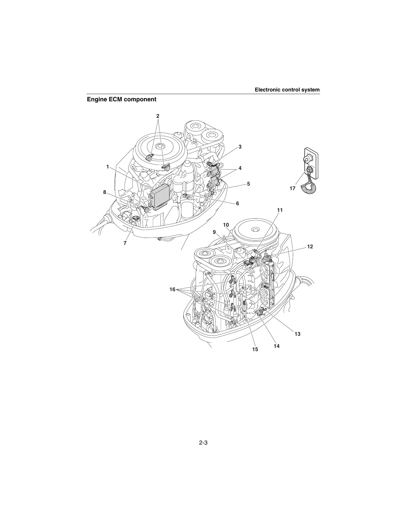
- Electronic control system and engine ECM components
- Engine-speed and fail-safe control
- Y-COP, tilt limiter and YDIS
- Fuel, vapor-gas, lubrication and cooling systems
- Intake and exhaust system
- SDS propeller and PTT operating functions
- Rigging information
- Outboard mounting, external dimensions and clamp bracket
- Shift and throttle cable installation
- 6Y8 Multifunction Meter and conventional-gauge harnesses
- Water-pressure sensor, speed sensor and tilt limiter
- Y-COP installation and receiver registration
- Battery wiring and single/twin-engine system diagrams
- Battery-cable extension and propeller selection
- Troubleshooting
- YDIS functions and communication connection
- Trouble-code diagnosis and checking steps
- Diagnostic flash indicator
- Power-unit troubleshooting without detected trouble codes
- PTT-unit and lower-unit troubleshooting
- Electrical system
- Electrical components and wiring-harness routing
- ECM circuit and coupler layout
- Engine, fuel, charging, ignition and starting components
- Y-COP checks and starter-motor overhaul
- 6Y8 sensors and PTT-system checks
- Fuel system
- Fuel, air, pressure-regulator, vapor-gas and cooling-water hose routing
- Fuel pressure, fuel filter and fuel pump
- Canister and vapor shut-off valve
- Throttle link, throttle body and synchronization
- Fuel injectors, fuel rail and fuel cooler
- Intake manifold, vapor separator and high-pressure fuel pump
- Power unit
- Compression, oil pressure and valve-clearance checks
- Power-unit removal and installation
- Flywheel magnet, stator, timing belt and starter motor
- Camshaft and cylinder-head overhaul
- Valve, guide and valve-seat inspection
- Oil pump, balancer and crankcase service
- Pistons, cylinders, connecting rods, crankshaft and bearing selection
Complete PDF Bookmark TreeComplete Bookmarks
The complete bookmarks in the βYamaha F150A FL150A F150B FL150B 150HP Outboard Service Manual PDFβ are as follows:
+Contentsp. 3
+General informationp. 5
+!Safety while workingp. 6
Rotating partp. 6Hot partp. 6Electric shockp. 6Propellerp. 6Handling of gasolinep. 6Ventilationp. 6Self-protectionp. 7Working with cranep. 7Handling of gas torchp. 7Part, lubricant, and sealantp. 7Handling of sealantp. 8Special service toolp. 8Tightening torquep. 8Non-reusable partp. 8Disassembly and assemblyp. 8+How to use this manualp. 9
Manual formatp. 9Abbreviationp. 10+Lubricant, sealant, and thread locking agentp. 11
Symbolp. 11Special service toolp. 13+Specificationp. 22
+Model featurep. 24
General featurep. 24Model name designationp. 25Serial numberp. 26+Model datap. 27
Dimension and weightp. 27Performancep. 27Power unitp. 28Lower unitp. 28Bracket unitp. 28Fuel and oil requirementp. 29Battery requirementp. 29PTT fluid requirementp. 29+Electrical technical datap. 30
Ignition timing control systemp. 30Fuel injection control systemp. 31Engine speed control systemp. 31PTT systemp. 31Charging systemp. 32Starting systemp. 32Y-COP (standard for European market and optional for Oceanian market)p. 32Gauge/sensorp. 33+Fuel system technical datap. 34
Fuel systemp. 34+Power unit technical datap. 35
Power unitp. 35Cylinder head assemblyp. 35Crankcase assemblyp. 36+Lower unit technical datap. 38
Lower unit assembly (regular rotation model)p. 38Lower unit assembly (counter rotation model)p. 38+Bracket unit technical datap. 39
PTT systemp. 39+Specified tightening torquep. 40
Rigging informationp. 40Electrical systemp. 40Fuel systemp. 40Power unitp. 41Lower unit (regular rotation model)p. 42Lower unit (counter rotation model)p. 42Bracket unitp. 42PTT unitp. 43General tightening torquep. 43+Technical feature and descriptionp. 44
+Electronic control systemp. 46
Engine ECM componentp. 48Engine speed controlp. 50Fail-safe controlp. 51+Additional featuresp. 52
Y-COP (standard for European market and optional for Oceanian market)p. 52Tilt limiter (F150A, FL150A [optional for European and Oceanian markets])p. 53+YDISp. 54
Overviewp. 54New functionsp. 55Loggingp. 56+Power unit systemp. 57
Shimless valve lifterp. 57+Fuel systemp. 58
Fuel diagramp. 58Vapor gas diagramp. 59+Lubrication systemp. 60
Lubrication diagramp. 60+Cooling systemp. 61
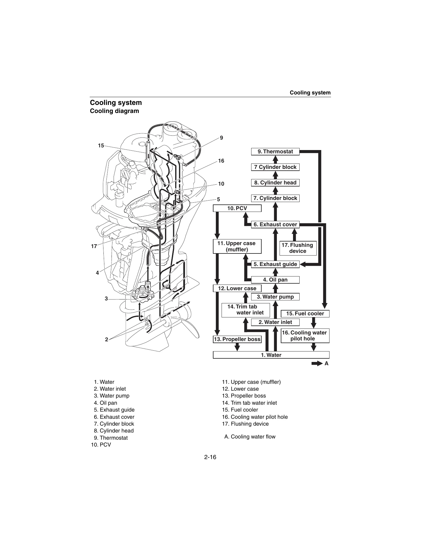
Cooling diagramp. 61+Intake and exhaust systemp. 62
Intake and exhaust diagramp. 62+Lower unitp. 63
Propeller (SDS)p. 63+PTT unitp. 64
Trim-up and tilt-up functionp. 64Trim-down and tilt-down functionp. 65Trim ram retraction when tilting the outboard motor upp. 66Trim ram retraction when there is no load on the tilt ram and trim ramp. 66Stationary conditionp. 67Shock-absorbing functionp. 67+Rigging informationp. 68
+Important reminder on riggingp. 70
Outboard motor mounting instructionsp. 70+Crate handlingp. 71
Crate top cover pictograph descriptionp. 71+Uncratingp. 72
Uncrating procedurep. 72+External dimensionsp. 74
F150A, FL150A, F150B, FL150Bp. 74Clamp bracketp. 75+Outboard motor mountingp. 76
Installing the outboard motorp. 76+Rigging grommet mountingp. 78
Rigging grommet descriptionp. 78Installing the shift cablep. 78Installing the throttle cablep. 80Installing the 6Y8 Multifunction Meter harnessp. 81Installing the conventional gauge harnessp. 81Installing the main wiring harnessp. 82Installing the rigging grommetp. 82+Optional equipmentp. 83
Installing the isolator leadp. 83Installing the water pressure sensorp. 83Installing the speed sensorp. 84Installing the tilt limiterp. 85Setting the tilt limiterp. 87Deactivating the tilt limiterp. 89+Y-COP (standard for European market and optional for Oceanian market)p. 89
Installing Y-COPp. 89Registering the receiver ID to the ECMp. 89+Battery installationp. 91
Battery wiring without house (accessory) batteryp. 91Battery wiring with house (accessory) batteryp. 94+System diagramp. 98
Single outboard motor application (6Y8 Multifunction Meter)p. 98Single outboard motor application (conventional gauge)p. 100Twin outboard motor application (6Y8 Multifunction Meter)p. 102Twin outboard motor application (conventional gauge)p. 104+Rigging recommendationp. 106
Extension length recommendation for battery cablep. 106+Propeller selectionp. 107
Propeller sizep. 107Selectionp. 107+Troubleshootingp. 111
+YDISp. 112
Basic componentsp. 112Functionp. 113Connecting the communication cablep. 116+Outboard motor troubleshootingp. 117
Troubleshooting procedurep. 117Troubleshooting the power unit using the YDISp. 117Trouble code and checking stepp. 119Troubleshooting the power unit using the diagnostic flash indicatorp. 121Troubleshooting the power unit (trouble code not detected)p. 122Troubleshooting the PTT unitp. 127Troubleshooting the lower unitp. 128+Electrical systemp. 130
+Electrical component and wiring harness routingp. 132
Portp. 132Junction box assemblyp. 134Rearp. 136Topp. 137Bottom cowlingp. 138+ECM circuitp. 140
Circuit diagramp. 140ECM coupler layoutp. 142+Checking the electrical componentp. 143
Using the YDISp. 143Measuring the peak voltagep. 143Using the digital testerp. 144+Engine control unit and componentp. 144
Checking the main relayp. 144Checking the engine ECM circuitp. 145Checking the TPSp. 146Checking the ISC valvep. 146Checking the oil pressure sensorp. 147+Fuel control unit and componentp. 147
Checking the water detection switchp. 147Checking the fuel injectorp. 148Checking the high-pressure fuel pumpp. 149Checking the vapor shut-off valvep. 149+Charging unit and componentp. 150
Checking the lighting coil (stator assembly)p. 150Checking the Rectifier Regulatorp. 150+Ignition unit and componentp. 152
Checking the ignition sparkp. 152Checking the spark plug wirep. 152Checking the ignition coilp. 152Checking the pulser coilp. 153Checking the air temperature sensorp. 154Checking the air pressure sensorp. 155Checking the engine temperature sensorp. 155Checking the thermoswitchp. 156Checking the shift cut-off switchp. 157Checking the shift position switchp. 157Checking the engine shut-off switchp. 158+Starting unit and componentp. 158
Checking the starter relayp. 158Checking the engine start switchp. 159+Y-COP (standard for European market and optional for Oceanian market)p. 160
Checking Y-COPp. 161Checking the buzzerp. 161Checking the Y-COP main wiring harnessp. 161Checking the button cell batteryp. 162+Starter motorp. 164
Removing the starter motorp. 166Checking the starter motor pinionp. 166Disassembling the starter motorp. 166Checking the armature (starter motor)p. 168Checking the brush holderp. 168Assembling the starter motorp. 169Installing the starter motorp. 170+6Y8 Multifunction Meter sensorp. 171
Checking the water pressure sensor (optional)p. 171Checking the speed sensor (optional)p. 171+PTT systemp. 172
Checking the PTT relayp. 172Checking the PTT switch (on bottom cowling)p. 173Checking the trim sensorp. 173Checking the tilt limiter (optional)p. 174+Fuel systemp. 176
+Hose routingp. 178
Fuel hosep. 178Air hose, pressure regulator hose, and vapor gas hosep. 179Blowby hose and cooling water hosep. 181+Fuel linep. 182
Reducing the fuel pressurep. 182Measuring the fuel pressurep. 182Checking the pressure regulatorp. 182+Fuel filterp. 184
Removing the fuel filter assemblyp. 185Checking the fuel filter assemblyp. 185Disassembling the fuel filter assemblyp. 186Checking the fuel filter elementp. 186Checking the fuel cup assemblyp. 186Checking the primer pumpp. 186Assembling the fuel filter assemblyp. 186Installing the fuel filter assemblyp. 187+Fuel pumpp. 188
Removing the fuel pump assemblyp. 190Checking the fuel pump assemblyp. 190Disassembling the fuel pump assemblyp. 191Checking the diaphragm and valvep. 191Assembling the fuel pump assemblyp. 191Installing the fuel pump assemblyp. 192+Canister and vapor shut-off valvep. 194
Removing the canisterp. 195Removing the vapor shut-off valvep. 195Checking the canisterp. 195Checking the vapor shut-off valvep. 196Installing the vapor shut-off valvep. 196Installing the canisterp. 196Intake silencerp. 198+Throttle linkp. 199
Removing the throttle linkp. 200Checking the throttle linkp. 200Installing the throttle linkp. 200+Throttle bodyp. 202
Removing the throttle body assemblyp. 203Checking the TPSp. 203Installing the throttle body assemblyp. 203+Throttle body and throttle link adjustmentp. 204
Adjusting the throttle linkp. 204Adjusting the throttle valve reference opening anglep. 204Checking the synchronization of the throttle valvep. 206+Fuel injectorp. 207
Removing the fuel injectorp. 208Removing the fuel coolerp. 208Checking the fuel rail and fuel injectorp. 209Installing the fuel coolerp. 209Installing the fuel injectorp. 210+Intake manifold and vapor separatorp. 211
Draining the fuelp. 214Removing the intake manifoldp. 214Removing the vapor separatorp. 214Checking the fuel filterp. 215Checking the intake manifoldp. 215Checking the air pressure sensorp. 215Checking the ISC valvep. 215Installing the vapor separatorp. 216Installing the intake manifoldp. 217+Vapor separator and high-pressure fuel pumpp. 219
Disassembling the vapor separatorp. 220Checking the high-pressure fuel pumpp. 220Checking the vapor separatorp. 220Assembling the vapor separatorp. 221+Power unitp. 223
+Power unit (check and adjustment)p. 226
Checking the compression pressurep. 226Checking the oil pressurep. 226Checking the valve clearancep. 226Adjusting the valve clearancep. 228+Power unit assemblyp. 230
Removing the power unitp. 232Installing the power unitp. 234+Flywheel magnetp. 237
Removing the flywheel magnetp. 238Removing the stator assemblyp. 238Installing the stator assemblyp. 239Installing the flywheel magnetp. 240+Timing beltp. 241
Removing the timing beltp. 242Removing the drive sprocketp. 242Checking the timing beltp. 242Installing the drive sprocketp. 242Installing the timing beltp. 243+Starter motorp. 245
Removing the starter motorp. 246Installing the starter motorp. 246+Rectifier Regulator and ignition coilp. 248
Removing the Rectifier Regulatorp. 250Removing the ignition coilp. 250Checking the spark plugp. 250Installing the ignition coilp. 251Installing the Rectifier Regulatorp. 251Fuse boxp. 252+Wiring harnessp. 253
Removing the wiring harnessp. 255Installing the wiring harnessp. 256+Camshaftp. 258
Removing the driven sprocket and camshaftp. 260Checking the driven sprocketp. 260Checking the camshaftp. 260Installing the driven sprocket and camshaftp. 261+Cylinder headp. 263
Removing the cylinder headp. 265Disassembling the cylinder headp. 265Checking the valve lifterp. 265Checking the cylinder headp. 266Checking the valve springp. 266Checking the valvep. 266Checking the valve guidep. 267Replacing the valve guidep. 267Checking the valve seatp. 268Refacing the valve seatp. 268Checking the cylinder head and cylinder block anodep. 270Assembling the cylinder headp. 270Installing the cylinder headp. 271+Exhaust coverp. 273
Removing the exhaust coverp. 275Checking the PCVp. 275Checking the thermostatp. 275Checking the exhaust cover anodep. 275Installing the exhaust coverp. 276+Cylinder block (F150A, FL150A)p. 277
Removing the oil pump assemblyp. 279Removing the oil filter bracketp. 279Removing the balancer assemblyp. 279Disassembling the oil pumpp. 279Checking the oil pumpp. 279Assembling the oil pumpp. 279Installing the oil pump assemblyp. 280Installing the balancer assemblyp. 280Installing the oil filter bracketp. 281+Cylinder block (F150B, FL150B)p. 283
Removing the oil pump assemblyp. 285Removing the oil filter bracketp. 285Removing the crankcase coverp. 285Disassembling the oil pumpp. 285Checking the oil pumpp. 285Assembling the oil pumpp. 285Installing the oil pump assemblyp. 285Installing the crankcase coverp. 285Installing the oil filter bracketp. 285+Crankcasep. 286
Disassembling the cylinder blockp. 288Checking the piston diameterp. 289Checking the cylinder borep. 289Checking the piston ringp. 289Checking the piston ring end gapp. 290Checking the piston ring groovep. 290Checking the piston ring side clearancep. 290Checking the piston pin boss inside diameterp. 290Checking the piston pin diameterp. 291Checking the connecting rod small end inside diameter and big end inside diameterp. 291Checking the connecting rod big end side clearancep. 291Checking the crankshaftp. 291Checking the big end oil clearancep. 292Selecting the crankpin bearingp. 293Crankpin bearing selection tablep. 295Checking the journal oil clearancep. 296Selecting the crankshaft journal bearingp. 297Crankshaft journal bearing selection tablep. 299Assembling the cylinder blockp. 300+Lower unitp. 304
+Lower unit (regular rotation model, L-transom model)p. 308
Removing the lower unitp. 310Disassembling the propeller (SDS propeller)p. 310Checking the propellerp. 310Checking the lower unit anodep. 310Assembling the propeller (SDS propeller)p. 311+Lower unit (regular rotation model, X-transom model)p. 313
Removing the lower unitp. 315Disassembling the propeller (SDS propeller)p. 315Checking the propellerp. 315Checking the lower unit anodep. 315Assembling the propeller (SDS propeller)p. 315+Water pump and shift rod (regular rotation model)p. 316
Removing the water pump and shift rodp. 318Disassembling the water pump housingp. 318Checking the water pump and shift rodp. 318Assembling the water pump housingp. 319+Propeller shaft housing (regular rotation model)p. 320
Removing the propeller shaft housing assemblyp. 322Disassembling the propeller shaft assemblyp. 322Disassembling the propeller shaft housing assemblyp. 323Checking the propeller shaftp. 323Checking the dog clutchp. 323Checking the propeller shaft housingp. 323Checking the reverse gearp. 323Assembling the propeller shaft assemblyp. 324Assembling the propeller shaft housing assemblyp. 324+Drive shaft and lower case (regular rotation model)p. 326
Removing the drive shaftp. 328Disassembling the drive shaft housingp. 328Disassembling the forward gearp. 328Disassembling the lower casep. 329Checking the pinionp. 329Checking the forward gearp. 329Checking the drive shaftp. 329Checking the lower casep. 330Assembling the forward gearp. 330Assembling the drive shaft housingp. 330Assembling the lower casep. 331Installing the drive shaftp. 332Installing the propeller shaft housing assemblyp. 333Installing the shift rodp. 334Installing the water pumpp. 334Checking the lower unit for air leakagep. 335Installing the lower unit (L-transom model)p. 336Installing the lower unit (X-transom model)p. 337+Shimming (regular rotation model)p. 339
Shimming workflowp. 339Shimming check sheetp. 340Measuring the forward gear backlash and reverse gear backlash before disassemblyp. 342Shimming procedurep. 345Shim locationp. 345Selecting the pinion shim (T3)p. 346Measuring the forward gear backlashp. 348Adjusting the forward gear shim thickness (T1)p. 348Measuring the reverse gear backlashp. 350Adjusting the reverse gear shim thickness (T2)p. 350+Lower unit (counter rotation model, L-transom model)p. 352
Removing the lower unitp. 354Disassembling the propeller (SDS propeller)p. 354Checking the propellerp. 354Checking the lower unit anodep. 354Assembling the propeller (SDS propeller)p. 354+Lower unit (counter rotation model, X-transom model)p. 355
Removing the lower unitp. 357Disassembling the propeller (SDS propeller)p. 357Checking the propellerp. 357Checking the lower unit anodep. 357Assembling the propeller (SDS propeller)p. 357+Water pump and shift rod (counter rotation model)p. 358
Removing the water pump and shift rodp. 360Disassembling the water pump housingp. 360Checking the water pump and shift rodp. 360Assembling the water pump housingp. 360+Propeller shaft housing (counter rotation model)p. 361
Removing the propeller shaft housing assemblyp. 363Disassembling the propeller shaft housing assemblyp. 363Disassembling the forward gearp. 363Checking the propeller shaftp. 364Checking the dog clutchp. 364Checking the propeller shaft housingp. 364Checking the forward gearp. 364Assembling the propeller shaft housing assembly and forward gearp. 364+Drive shaft and lower case (counter rotation model)p. 367
Removing the drive shaftp. 369Removing the reverse gearp. 369Disassembling the drive shaft housingp. 369Disassembling the reverse gearp. 369Disassembling the lower casep. 369Checking the pinionp. 370Checking the reverse gearp. 370Checking the drive shaftp. 370Checking the lower casep. 370Assembling the reverse gearp. 370Assembling the lower casep. 370Assembling the drive shaft housingp. 371Installing the reverse gearp. 371Installing the drive shaftp. 371Installing the propeller shaft housing assemblyp. 371Installing the shift rodp. 371Installing the water pumpp. 371Checking the lower unit for air leakagep. 371Installing the lower unit (L-transom model)p. 371Installing the lower unit (X-transom model)p. 372+Shimming (counter rotation model)p. 373
Shimming workflowp. 373Shimming check sheetp. 374Measuring the forward gear backlash and reverse gear backlash before disassemblyp. 376Shimming procedurep. 379Shim locationp. 379Selecting the pinion shim (T3)p. 380Selecting the propeller shaft shim (T4)p. 380Measuring the forward gear backlashp. 381Adjusting the forward gear shim thickness (T2)p. 381Measuring the reverse gear backlashp. 383Adjusting the reverse gear shim thickness (T1)p. 383+Bracket unitp. 386
+Shift rod and shift bracketp. 388
Removing the shift rod and shift bracketp. 390Disassembling the shift bracketp. 390Assembling the shift bracketp. 390Installing the shift rod and shift bracketp. 391+PTT switch and cowling lock leverp. 393
Removing the PTT switchp. 395Removing the cowling lock leverp. 395Removing the flushing hosep. 395Installing the flushing hosep. 395Installing the cowling lock leverp. 396Installing the PTT switchp. 396Bottom cowlingp. 398+Upper case and mountsp. 400
Removing the upper casep. 402Installing the upper casep. 402+Upper casep. 404
Disassembling the upper casep. 405Checking the drive shaft bushingp. 405Assembling the upper casep. 405+Oil pan and exhaust manifoldp. 407
Disassembling the oil pan and exhaust manifoldp. 409Checking the oil pan and exhaust manifoldp. 409Checking the oil strainerp. 409Assembling the oil pan and exhaust manifoldp. 409+Steering armp. 411
Removing the steering armp. 412Installing the steering armp. 412+Clamp bracket and swivel bracketp. 414
Removing the clamp bracketp. 417Checking the clamp bracket anodep. 417Installing the clamp bracketp. 417Adjusting the trim sensor camp. 419+PTT unitp. 420
Removing the PTT unitp. 421Checking the hydraulic pressurep. 422Bleeding the PTT unitp. 424Installing the PTT unitp. 426+PTT cylinderp. 428
Removing the tilt ram and trim ramp. 430Disassembling the tilt ramp. 431Disassembling the trim ramp. 431Checking the tilt cylinder and trim cylinderp. 431Checking the absorber valvep. 431Assembling the tilt ramp. 431Assembling the trim ramp. 432Installing the trim ramp. 433Installing the tilt ramp. 433+PTT motorp. 435
Removing the reservoirp. 437Removing the PTT motorp. 437Disassembling the PTT motorp. 437Checking the armature (PTT motor)p. 438Checking the brushp. 438Checking the reservoirp. 439Assembling the PTT motorp. 439Installing the PTT motorp. 440Installing the reservoirp. 440+PTT gear pumpp. 441
Removing the gear pump assemblyp. 444Disassembling the gear pump housingp. 444Disassembling the gear pumpp. 444Checking the gear pumpp. 445Checking the gear pump housingp. 445Checking the valve sealp. 445Checking the filterp. 445Assembling the gear pumpp. 446Assembling the gear pump housingp. 447Installing the gear pump assemblyp. 448+Maintenancep. 450
+Outlinep. 452
Maintenance interval chart 1p. 452Maintenance interval chart 2p. 454+Predelivery checkp. 455
Checking the batteryp. 455Checking the cooling water pilot holep. 456Checking the engine oil levelp. 456Checking the main switch/stop switch/choke switchp. 456Checking the fuel linep. 457Checking the gear oil levelp. 457Checking the shift link/shift cable and throttle link/throttle cable/ throttle pick-up timingp. 457Checking the outboard motor mounting heightp. 457Checking the power trim and tilt unitp. 458Checking the steering systemp. 458Checking the throttle cable and shift cablep. 458Test runp. 458Break-inp. 459After test runp. 459+General periodic maintenancep. 459
Checking the anodep. 459Checking the batteryp. 459Checking the cooling water inletp. 459Checking the cooling water pilot holep. 460Checking the engine idle speed/ noisep. 460Changing the engine oilp. 460Checking the engine oil levelp. 461Replacing the oil filterp. 461Checking the exhaust guide/exhaust manifoldp. 462Checking the main switch/stop switch/choke switchp. 462Checking the fuel filterp. 462Checking the fuel pumpp. 462Checking for fuel leakage/oil leakagep. 462Changing the gear oilp. 462Checking the gear oil levelp. 463Greasing pointsp. 463Checking the PCVp. 465Checking the propeller/propeller nut/ cotter pinp. 465Checking the PTT fluid levelp. 465Checking the power trim and tilt unit operationp. 465Adjusting the shift link/shift cablep. 466Checking the spark plugp. 466Checking the timing beltp. 466Replacing the timing beltp. 466Checking the thermostatp. 466Adjusting the throttle link/throttle cable/throttle pick-up timingp. 466Checking the cowling lock leverp. 466Checking the valve clearancep. 466Checking the impeller/water pump housingp. 466Indexp. 467+Appendixp. 477
+Wiring diagramp. 477
How to use the wiring diagramp. 477Engine control unit and fuel unitp. 478Ignition unitp. 480Charging unit and starting unit (F150A, FL150A for European and Oceanian markets)p. 482Charging unit and starting unit (F150A, FL150A [except for European and Oceanian markets] and F150B, FL150B)p. 484Control unitp. 486+Shim selection table and chart (regular rotation model)p. 488
Pinion shim (T3) selection tablep. 488Forward gear shim (T1) selection chart (F150A)p. 489Reverse gear shim (T2) selection chart (F150A)p. 489Forward gear shim (T1) selection chart (F150B)p. 490Reverse gear shim (T2) selection chart (F150B)p. 490+Shim selection table and chart (counter rotation model)p. 491
Pinion shim (T3) selection tablep. 491Propeller shaft shim (T4) selection tablep. 491Forward gear shim (T2) selection chart (FL150A)p. 492Reverse gear shim (T1) selection chart (FL150A)p. 492Forward gear shim (T2) selection chart (FL150B)p. 493Reverse gear shim (T1) selection chart (FL150B)p. 493 - Lower unit
- Regular-rotation and counter-rotation lower units
- Water pump and shift rod
- Propeller-shaft housing, dog clutch and gears
- Drive shaft and lower case
- Gear backlash, shimming and lower-unit leakage checks
- Bracket unit
- Shift rod, shift bracket, PTT switch and cowling lock lever
- Upper case, mounts, oil pan and exhaust manifold
- Steering arm, clamp bracket and swivel bracket
- PTT hydraulic-pressure checks and bleeding
- PTT cylinder, motor, reservoir and gear pump
- Maintenance
- Maintenance interval charts
- Predelivery checks and test run
- Break-in procedures
- Engine oil, oil filter and gear-oil service
- Fuel, ignition, cooling, propeller and PTT inspections
- Timing-belt, thermostat, valve-clearance and water-pump maintenance
Taken together, these chapters give technicians a connected service path from identifying the correct model and specifications through fault diagnosis, electrical testing, component removal, inspection, adjustment, overhaul, reassembly and scheduled maintenance. The document is particularly detailed in areas where exact measurements matter, including valve clearances, sensor values, fuel and hydraulic pressures, gear backlash, bearing and piston measurements, service limits and fastener torque specifications.
Fuel, Cooling, Lubrication and PTT System Detail
The fuel-system material traces the circuit from the primer pump and fuel filter through low-pressure pumps, vapor separator, high-pressure fuel pump, fuel rail and injectors. Service procedures include fuel-pressure measurement, pressure-regulator checks, pump and diaphragm inspection, throttle-body adjustment, TPS adjustment, throttle synchronization, injector work and vapor-separator service.
Separate diagrams explain engine-oil flow, cooling-water flow, intake and exhaust routing and the PTT hydraulic circuit. The PTT section describes trim-up, tilt-up, trim-down and tilt-down operation, relief-valve action, trim-ram retraction, stationary hydraulic conditions and the shock-absorbing function. Later repair chapters cover hydraulic-pressure testing, bleeding, cylinder service, PTT motor inspection and gear-pump disassembly and checking.
Maintenance and Setup Reference
This service manual is also useful beyond major repairs. Maintenance interval charts support routine inspection planning, while the predelivery and rigging sections cover mounting, control-cable setup, electrical harnesses, battery arrangements, sensor installation and propeller selection. Periodic procedures address anodes, battery condition, cooling-water flow, engine oil and filter service, fuel components, gear oil, lubrication points, spark plugs, timing belt, thermostat, valve clearance, propeller hardware and the water pump.
Service and Repair with the Correct Procedures at Hand
The Yamaha F150A FL150A F150B FL150B 150HP Outboard Service Manual PDF supports everything from routine inspection and rigging work to fault-code diagnosis, electrical testing, fuel-system repair, power-unit disassembly, cylinder-head and crankcase work, lower-unit overhaul and PTT repair. Having the specified measurements, tightening torques, adjustment values, wiring information and illustrated assembly sequences available during the job helps technicians follow the procedures and specifications intended for these particular Yamaha outboards rather than relying on generic repair information.
Your manual is supplied as an instant PDF download after purchase. There is no physical book and no shipping delay. Open the PDF on a computer, tablet or compatible mobile device and print the pages you need for workshop use.
What Our Customers Say
π Related Products
Discover more professional manuals for your equipment

2013 Yamaha F200F FL200F Outboard Service Manual 6DA-28197-3S-11

Yamaha E115A 115B 140B Outboard Service Repair Manual 61U-28197-5H-11 PDF


Reviews
There are no reviews yet.