Description
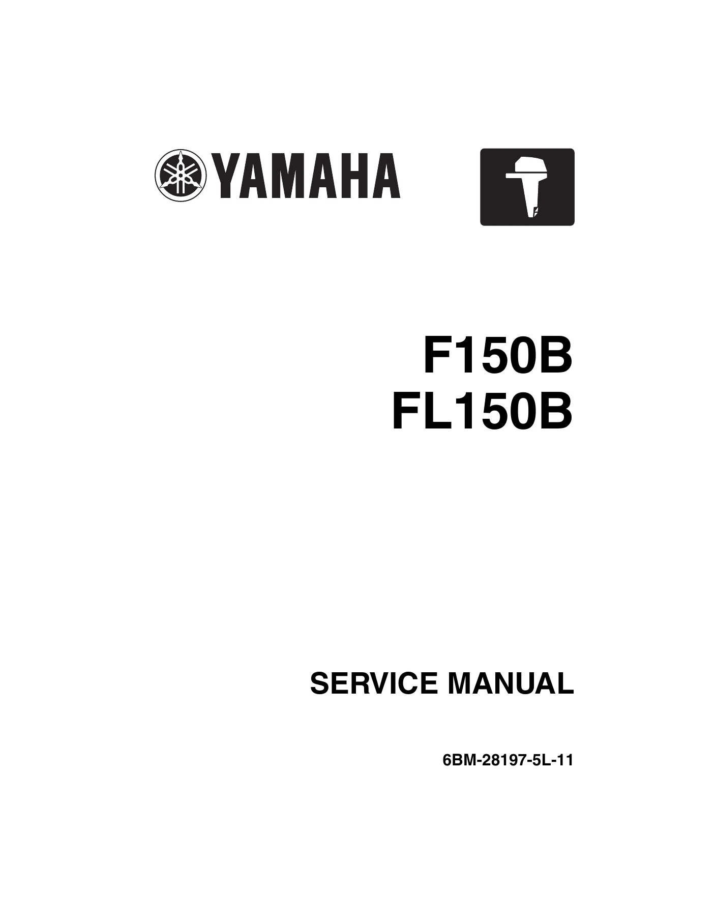
Yamaha F150B FL150B Service Manual – 6BM-28197-5L-11
This is the complete Yamaha service manual for the F150B and FL150B 4-stroke outboard motors, published under document number 6BM-28197-5L-11 (1st Edition, June 2008). It is the same manual used in Yamaha dealer workshops for maintenance, repair, and overhaul of these 150 HP four-stroke outboards. Every major system is covered, from the electronic fuel injection and ignition control through to the lower unit, bracket, and power trim and tilt.
File Details
- Manual type: Service Manual (workshop repair and maintenance)
- Brand: Yamaha
- Models covered: F150B, FL150B (4-stroke, 150 HP)
- Document number: 6BM-28197-5L-11
- Edition: 1st Edition, June 2008
- Language: English
- Format: PDF
- Page count: 458 pages
Chapters Covered
- General Information – Safety while working, how to use this manual, abbreviations, sealants and locking agents, special service tools, tightening torque
- Specification – Model data, dimensions and weight, performance, power unit, lower unit, bracket unit, fuel and oil requirements, battery and PTT requirements, electrical technical data, fuel system technical data, power unit technical data, lower unit technical data, bracket unit technical data, tightening torques
- Technical Features and Description – Electronic control system, ECM component, sensor switch and actuator, electronic fuel injection control system, ignition timing control system, engine speed control system, idle speed control, fail-safe control, power unit system, lubrication system, cooling system, intake and exhaust system, idle exhaust system, PTT unit operation
- Rigging Information – Outboard motor installation, dimensions, crate handling, uncrate procedure, outboard motor mount, rigging grommet, shift cable, throttle cable, isolator lead, gauge harness, water temperature sensor, 6Y8 Multifunction Meter harness, speed sensor, water pressure sensor, main wiring harness, fuel flow sensor, remote control box, battery wiring, system diagrams, battery cable extension, propeller selection
- Troubleshooting – YDIS, hardware requirements, functions, connecting the communication cable, troubleshooting the power unit using YDIS, trouble code and checking step, diagnostic flash indicator, troubleshooting the power unit without trouble codes, PTT unit, lower unit
- Electrical System – Port view, junction box assembly, aft view, bow view, top view, wiring harness routing, circuit diagram, ECM coupler layout, checking electrical components, engine control units and components, fuel control units and components, charging units and components, ignition units and components, starting units and components, starter motor, PTT system
- Fuel System – Fuel hose and blowby hose, vapor gas hose, cooling water hose, fuel line, reducing fuel pressure, measuring fuel pressure, pressure regulator, canister, fuel pump, fuel filter, intake silencer, throttle link, throttle body, fuel injector, intake manifold, vapor separator
- Power Unit – Power unit check and adjustment, compression pressure, oil pressure, valve clearance, flywheel magnet, wiring harness, starter motor, fuse box, junction box, timing belt, power unit assembly, camshaft, exhaust cover, cylinder head, cylinder block, crankcase
- Lower Unit – Regular rotation model and counter rotation model: lower unit removal, water pump and shift rod, propeller shaft housing, drive shaft and lower case, shimming procedures, shim selection charts, backlash measurement and adjustment
- Bracket Unit – Shift rod and shift bracket, PTT switch and cowling lock lever, bottom cowling, upper case and mounts, oil pan and exhaust manifold, steering arm, clamp bracket and swivel bracket, PTT unit, PTT motor, PTT gear pump, PTT cylinder
- Maintenance – Outline, predelivery check, general periodic maintenance, maintenance interval chart, engine oil, gear oil, filters, anodes, thermostat, timing belt, valve clearance, water pump, propeller, spark plugs, PTT fluid
- Index – Alphabetical index of all sections and procedures
- Appendix – Wiring diagrams: fuel unit, ignition unit, charging unit and starting unit, color codes and symbols
Complete PDF Bookmark Tree
Complete Bookmarks
The complete bookmarks in the βYamaha F150B FL150B Outboard Motor Service Manual 2008 – Full Workshop PDFβ are as follows:
+Contentsp. 3
+General informationp. 5
+Safety while workingp. 6
Rotating partp. 6
Hot partp. 6
Electric shockp. 6
Propellerp. 6
Handling of gasolinep. 6
Ventilationp. 6
Self-protectionp. 7
Working with cranep. 7
Handling of burnerp. 7
Part, lubricant, and sealantp. 7
Handling of sealantp. 7
Special service toolp. 8
Tightening torquep. 8
Non-reusable partp. 8
Disassembly and assemblyp. 8
+How to use this manualp. 9
Manual formatp. 9
Abbreviationp. 10
+Sealant and locking agentp. 11
Special service toolp. 13
+Specificationp. 20
+Model featuresp. 22
General featurep. 22
Model designationp. 23
Serial numberp. 23
+Model datap. 24
Dimension and Weightp. 24
Performancep. 24
Power unitp. 24
Lower unitp. 25
Bracket unitp. 25
Fuel and oil requirementp. 25
Battery requirementp. 26
PTT requirementp. 26
+Electrical technical datap. 27
Ignition timing control systemp. 27
Fuel injection control systemp. 28
Engine speed control systemp. 29
PTT systemp. 29
Charging systemp. 30
Starting systemp. 30
Gauge / sensorp. 31
+Fuel system technical datap. 32
+Power unit technical datap. 33
Power unitp. 33
Cylinder head assemblyp. 33
Crankcase assemblyp. 35
+Lower unit technical datap. 37
Lower unit assembly (regular rotation model)p. 37
Lower unit assembly (counter rotation model)p. 37
+Bracket unit technical datap. 38
+Special tightening torquep. 39
Fuel systemp. 39
Power unitp. 39
Lower unit (regular rotation model)p. 40
Lower unit (counter rotation model)p. 41
Bracket unitp. 41
PTT unitp. 41
General tightening torquep. 42
+Technical features and descriptionp. 43
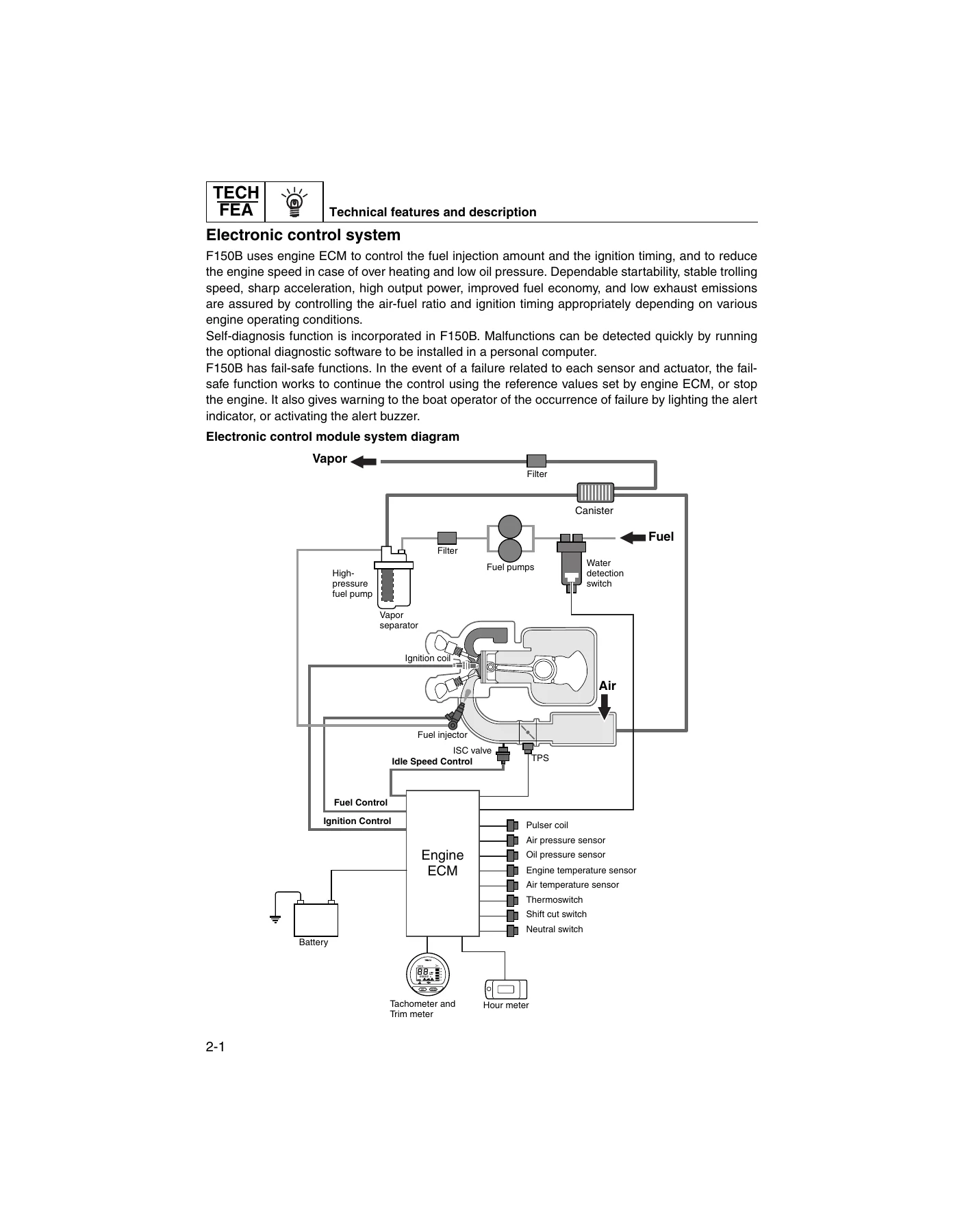
+Electronic control systemp. 44
Engine ECM componentp. 45
Sensor, switch and actuatorp. 47
Electronic fuel injection control systemp. 48
Ignition timing control systemp. 53
Engine speed control systemp. 56
Idle speed controlp. 59
Fail-safe controlp. 60
+Power unit systemp. 61
Lubrication systemp. 65
Cooling systemp. 67
+Intake and exhaust systemp. 70
+PTT unitp. 72
Trim-up and tilt-up functionp. 72
Trim ram retraction functionp. 73
Trim-down and tilt-down functionp. 74
Stationary conditionp. 75
When the outboard hits something in the waterp. 75
+Rigging informationp. 76
Outboard motor installationp. 78
+Dimensionsp. 79
Exteriorp. 79
Clamp bracketp. 80
Crate top cover pictograph descriptionp. 81
Uncrate procedurep. 82
Outboard motor mountp. 83
+Mounting the rigging grommetp. 85
Rigging grommet descriptionp. 85
Installing the shift cablep. 85
Installing the throttle cablep. 87
Installing the isolator lead (option)p. 88
Installing the gauge harnessp. 88
Installing the water temperature sensor (option)p. 89
Installing the 6Y8 Multifunction Meter harness (option)p. 89
Install the speed sensor (option for 6Y8 Multifunction Meter)p. 89
Installing the water pressure sensor (option for 6Y8 Multifunction Meter)p. 91
Installing the main wiring harnessp. 91
Installing the rigging grommetp. 92
Installing the fuel flow sensorp. 93
Remote control box and switch panel installationp. 93
+Installing the batteryp. 94
Battery wiring without house (accessory) batteryp. 94
Battery wiring with house (accessory) batteryp. 96
+System diagramp. 98
Single outboard motor applicationp. 98
Twin outboard motor applicationp. 100
+Rigging recommendationsp. 102
Extension length recommendation of battery cablep. 102
+Propeller selectionp. 103
Propeller sizep. 103
Selectionp. 103
+Troubleshootingp. 105
+YDISp. 106
Featurep. 106
Hardware requirementp. 106
Functionp. 107
YDIS kitp. 108
Connecting the communication cable to the outboard motorp. 108
+Troubleshooting the power unitp. 109
Troubleshooting procedurep. 109
Troubleshooting the power unit using the YDISp. 109
Trouble code and checking stepp. 111
Troubleshooting the power unit using the diagnostic flash indicatorp. 115
Troubleshooting the power unit (trouble code not detected)p. 116
Troubleshooting the PTT unitp. 122
Troubleshooting the lower unitp. 123
+Electrical systemp. 124
+Electrical componentsp. 126
Port viewp. 126
Junction box assemblyp. 127
Aft viewp. 128
Bow viewp. 129
Top viewp. 130
+Wiring harness routingp. 131
Port viewp. 131
Junction box assemblyp. 132
Aft viewp. 133
Top viewp. 134
Bottom cowlingp. 135
Circuit diagramp. 136
ECM coupler layoutp. 137
+Checking the electrical componentp. 138
Checking by use of YDISp. 138
Measuring the peak voltagep. 138
Checking by use of the digital testerp. 138
+Engine control units and componentsp. 139
Checking the main relayp. 139
Checking the engine ECM circuitp. 140
Checking the TPSp. 141
Checking the ISCp. 142
Checking the oil pressure sensorp. 144
Checking the hour meterp. 144
Checking the water pressure sensor (option)p. 146
Checking the speed sensor (option)p. 147
+Fuel control units and componentsp. 148
Checking the water detection switchp. 148
Checking the fuel injectorp. 149
Checking the high-pressure fuel pumpp. 150
+Charging units and componentsp. 151
Checking the lighting coil (stator assembly)p. 151
Checking the Rectifier Regulatorp. 152
+Ignition units and componentsp. 153
Checking the ignition sparkp. 153
Checking the spark plug wirep. 153
Checking the ignition coilp. 154
Checking the pulser coilp. 155
Checking the air temperature sensorp. 156
Checking the air pressure sensorp. 157
Checking the engine temperature sensorp. 158
Checking the thermoswitchp. 159
Checking the shift cut switchp. 161
Checking the neutral switchp. 162
Checking the engine shut-off switchp. 162
+Starting units and componentsp. 163
Checking the starter relayp. 163
Checking the engine start switchp. 164
Checking the neutral switch (remote control)p. 164
+Starter motorp. 165
Removing the starter motorp. 167
Checking the starter motor operationp. 167
Checking the magnet switchp. 167
Checking the starter motor pinionp. 167
Disassembling the starter motorp. 168
Checking the starter motorp. 169
Checking the brushp. 170
Assembling the starter motorp. 170
Installing the starter motorp. 172
+PTT systemp. 173
Checking the PTT relayp. 173
Checking the PTT switch (on bottom cowling)p. 174
Checking the trim sensorp. 175
+Fuel systemp. 176
+Hose routingp. 178
Fuel hose and blowby hosep. 178
Vapor gas hosep. 179
Cooling water hosep. 180
+Fuel linep. 181
Reducing the fuel pressurep. 181
Measuring the fuel pressurep. 181
Checking the pressure regulatorp. 182
+Canisterp. 183
Checking the canisterp. 184
Installing the canisterp. 184
+Fuel pumpp. 185
Checking the fuel pumpp. 187
Disassembling the fuel pumpp. 187
Checking the diaphragm and valvep. 188
Assembling the fuel pumpp. 188
Checking the primer pumpp. 189
+Fuel filterp. 190
Checking the fuel filter assemblyp. 191
Intake silencerp. 193
+Throttle linkp. 194
Checking the throttle linkp. 195
Installing the throttle linkp. 195
Adjusting the throttle linkp. 196
+Throttle bodyp. 197
Checking the TPSp. 198
Adjusting the TPSp. 198
Installing the throttle body assemblyp. 199
Adjusting the TPS (when disassembling or replacing the throttle body)p. 199
Synchronizing the throttle valvep. 200
+Fuel injectorp. 202
Checking the fuel railp. 203
Installing the fuel injectorp. 203
+Intake manifoldp. 204
Checking the intake manifoldp. 205
Checking the air pressure sensorp. 205
Checking the ISCp. 205
Installing the intake manifoldp. 205
+Vapor separatorp. 206
Draining the fuelp. 209
Checking the vacuum hosep. 209
Checking the fuel filterp. 209
Disassembling the vapor separatorp. 209
Checking the high-pressure fuel pumpp. 209
Checking the vapor separatorp. 209
Assembling the vapor separatorp. 210
+Power unitp. 212
+Power unit (check and adjustment)p. 214
Checking the compression pressurep. 214
Checking the oil pressurep. 215
Checking the valve clearancep. 215
Adjusting the valve clearancep. 216
+Flywheel magnetp. 218
Removing the flywheel magnetp. 219
Installing the flywheel magnetp. 219
+Wiring harnessp. 220
Removing the wiring harnessp. 221
Installing the wiring harnessp. 222
Starter motorp. 225
Fuse boxp. 227
Junction boxp. 228
+Timing beltp. 230
Replacing the timing beltp. 231
+Power unit assemblyp. 233
Removing the power unitp. 235
Installing the power unitp. 236
+Camshaftp. 239
Removing the timing belt, driven sprocket, and camshaftp. 241
Checking the timing belt and sprocketp. 242
Checking the camshaftp. 242
Installing the timing belt, driven sprocket, and camshaftp. 243
+Exhaust coverp. 245
Removing the exhaust coverp. 247
Checking the exhaust cover anodep. 247
Checking the PCVp. 247
Installing the PCVp. 247
Installing the exhaust coverp. 247
+Cylinder headp. 249
Removing the cylinder headp. 251
Checking the valve lifterp. 251
Checking the cylinder headp. 251
Checking the valve springp. 252
Checking the valvep. 252
Checking the valve guidep. 253
Replacing the valve guidep. 253
Checking the valve seatp. 254
Refacing the valve seatp. 254
Assembling the cylinder headp. 256
Installing the cylinder headp. 257
+Cylinder blockp. 258
Removing the oil pump assemblyp. 261
Removing the oil filter bracketp. 261
Removing the anode (cylinder block)p. 261
Removing the crankcase coverp. 261
Disassembling the oil pump assemblyp. 261
Checking the oil pump assemblyp. 261
Assembling the oil pump assemblyp. 262
Installing the oil pump assemblyp. 262
Installing the crankcase coverp. 263
Installing the oil filterp. 263
Installing the anode (cylinder block)p. 264
+Crankcasep. 265
Disassembling the cylinder blockp. 266
Checking the piston diameterp. 266
Checking the cylinder borep. 267
Checking the piston ringp. 267
Checking the piston ring end gap (reference)p. 267
Checking the piston ring groovep. 267
Checking the piston ring side clearancep. 268
Checking the connecting rod big end side clearancep. 268
Checking the crankshaftp. 268
Checking the crankpin oil clearancep. 269
Selecting the connecting rod bearingp. 270
Checking the crankshaft journal oil clearancep. 271
Selecting the main bearingp. 272
Assembling the cylinder blockp. 273
+Lower unitp. 277
+Lower unit (regular rotation model)p. 280
Removing the lower unitp. 282
+Water pump and shift rod (regular rotation model)p. 283
Removing the water pump and shift rodp. 285
Disassembling the water pump housingp. 285
Checking the water pump and shift rodp. 286
Assembling the water pump housingp. 286
+Propeller shaft housing (regular rotation model)p. 287
Removing the propeller shaft housing assemblyp. 289
Disassembling the propeller shaft assemblyp. 289
Disassembling the propeller shaft housing assemblyp. 290
Checking the propeller shaft housingp. 290
Checking the propeller shaftp. 290
Assembling the propeller shaft assemblyp. 290
Assembling the propeller shaft housing assemblyp. 291
+Drive shaft and lower case (regular rotation model)p. 293
Removing the drive shaftp. 295
Disassembling the drive shaft housingp. 295
Disassembling the forward gearp. 295
Disassembling the lower casep. 295
Checking the pinion and forward gearp. 296
Checking the drive shaftp. 296
Checking the lower casep. 296
Assembling the lower casep. 296
Assembling the forward gearp. 297
Assembling the drive shaft housingp. 298
Installing the drive shaftp. 299
Installing the propeller shaft housing assemblyp. 299
Installing the shift rodp. 300
Installing the water pumpp. 301
Checking the lower unit for air leakagep. 301
Installing the lower unitp. 302
+Shimming (regular rotation model)p. 304
Shimming workflowp. 304
Shimming check sheetp. 305
Measuring the forward and reverse gear backlash before disassemblyp. 307
Shimmingp. 310
Shim locationp. 311
Selecting the pinion shim (T3)p. 312
Pinion shim (T3) selection tablep. 315
Measuring the forward gear backlashp. 317
Adjusting the forward gear shim thickness (T1)p. 318
Forward gear shim (T1) selection chartp. 320
Measuring the reverse gear backlashp. 322
Adjusting the reverse gear shim thickness (T2)p. 322
Reverse gear shim (T2) selection chartp. 324
+Lower unit (counter rotation model)p. 326
Removing the lower unitp. 328
+Water pump and shift rod (counter rotation model)p. 329
Removing the water pump and shift rodp. 331
Disassembling the water pump housingp. 331
Checking the water pump and shift rodp. 331
Assembling the water pump housingp. 331
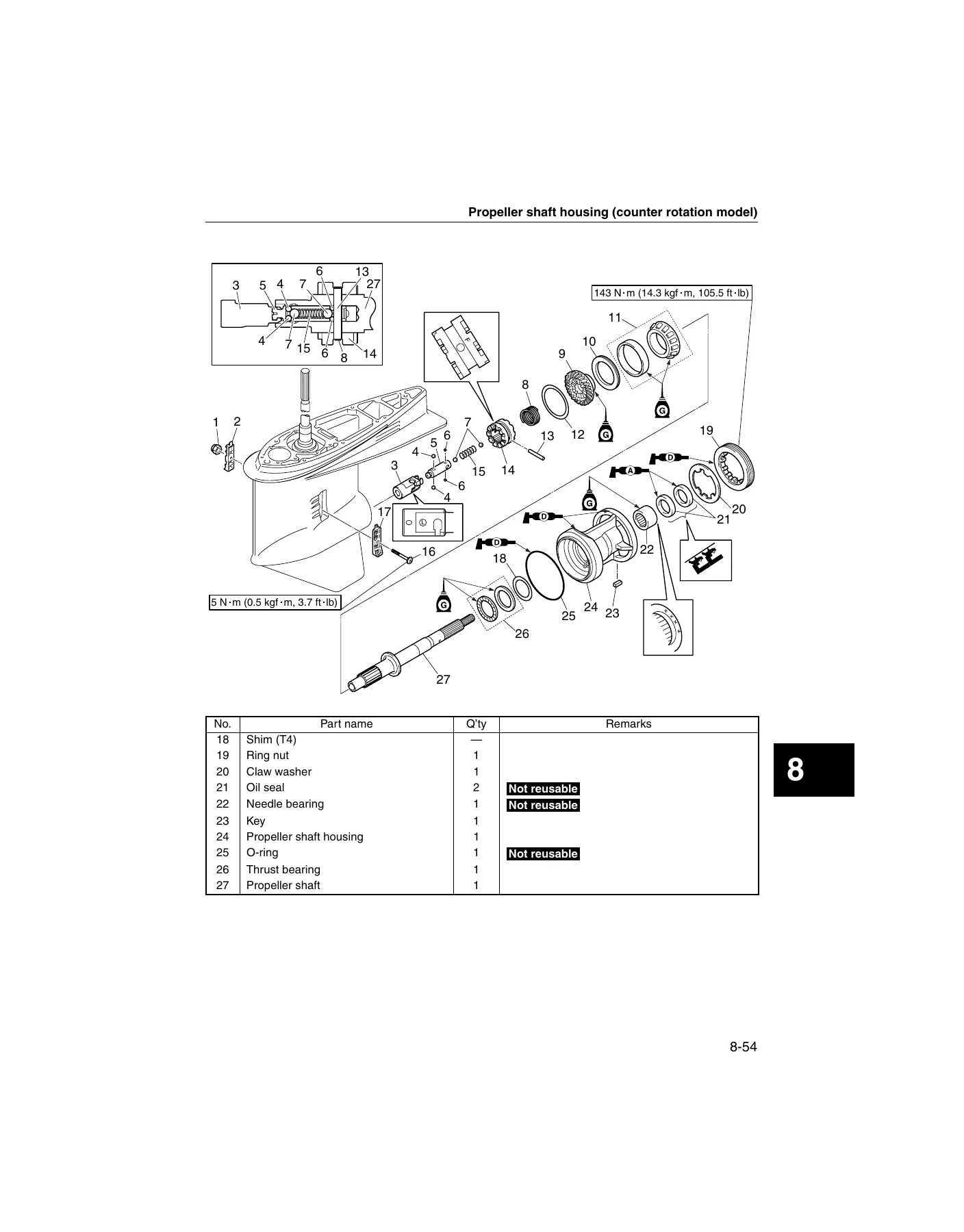
+Propeller shaft housing (counter rotation model)p. 332
Removing the propeller shaft housing assemblyp. 334
Disassembling the propeller shaft housing assemblyp. 334
Checking the propeller shaft housingp. 335
Checking the propeller shaftp. 335
Assembling the propeller shaft housing assemblyp. 336
+Drive shaft and lower case (counter rotation model)p. 338
Removing the drive shaftp. 340
Disassembling the drive shaft housingp. 340
Disassembling the reverse gearp. 340
Disassembling the lower casep. 340
Checking the pinion and reverse gearp. 341
Checking the drive shaftp. 341
Checking the lower casep. 341
Assembling the lower casep. 341
Assembling the reverse gearp. 342
Assembling the drive shaft housingp. 342
Installing the drive shaftp. 342
Installing the propeller shaft housing assemblyp. 342
Installing the shift rodp. 343
Installing the water pumpp. 343
Checking the lower unit for air leakagep. 343
Installing the lower unitp. 343
+Shimming (counter rotation model)p. 344
Shimming workflowp. 344
Shimming check sheetp. 345
Measuring the forward and reverse gear backlash before disassemblyp. 347
Shimmingp. 350
Shim locationp. 351
Selecting the pinion shim (T3)p. 352
Pinion shim (T3) selection tablep. 352
Selecting the propeller shaft shim (T4)p. 352
Propeller shaft shim (T4) selection tablep. 354
Measuring the forward gear backlashp. 355
Adjusting the forward gear shim thickness (T2)p. 355
Forward gear shim (T2) selection chartp. 357
Measuring the reverse gear backlashp. 359
Adjusting the reverse gear shim thickness (T1)p. 360
Reverse gear shim (T1) selection chartp. 362
+Bracket unitp. 364
+Shift rod and shift bracketp. 366
Removing the shift rod and shift bracketp. 368
Disassembling the shift bracketp. 368
Assembling the shift bracketp. 368
Installing the shift rod and shift bracketp. 370
+PTT switch and cowling lock leverp. 371
Removing the PTT switchp. 373
Removing the cowling lock leverp. 373
Removing the flushing hosep. 373
Installing the flushing hosep. 374
Installing the cowling lock leverp. 374
Installing the PTT switchp. 374
Bottom cowlingp. 375
+Upper case and mountsp. 377
Removing the upper casep. 379
Installing the upper casep. 379
+Upper casep. 381
Disassembling the upper casep. 382
Checking the drive shaft bushingp. 382
Assembling the upper casep. 382
+Oil pan and exhaust manifoldp. 384
Disassembling the oil pan and exhaust manifoldp. 386
Checking the oil pan and exhaust manifoldp. 386
Checking the oil strainerp. 386
Assembling the oil pan and exhaust manifoldp. 386
+Steering armp. 388
Removing the steering armp. 389
Installing the steering armp. 389
+Clamp bracket and swivel bracketp. 391
Removing the clamp bracketp. 394
Installing the clamp bracketp. 394
Adjusting the trim sensor camp. 396
+PTT unitp. 397
Removing the PTT unitp. 398
Checking the hydraulic pressurep. 399
Bleeding the PTT unitp. 401
Installing the PTT unitp. 401
+PTT motorp. 404
Removing the reservoirp. 406
Removing the PTT motorp. 406
Disassembling the PTT motorp. 406
Checking the PTT motorp. 407
Checking the brushp. 407
Assembling the PTT motorp. 408
Installing the reservoirp. 409
Installing the PTT motorp. 409
+PTT gear pumpp. 410
Disassembling the gear pump assemblyp. 412
Checking the gear pumpp. 412
Assembling the gear pump assemblyp. 413
+PTT cylinderp. 415
Removing the tilt ram and trim ramp. 417
Disassembling the tilt ramp. 417
Checking the tilt cylinder and trim cylinderp. 418
Checking the valvep. 418
Assembling the tilt ramp. 418
Assembling the trim ramp. 419
Installing the trim ramp. 420
Installing the tilt ramp. 421
+Maintenancep. 422
Outlinep. 424
+Predelivery checkp. 427
Checking the batteryp. 427
Checking the cooling water pilot holep. 427
Checking the engine oil levelp. 428
Checking the engine start switch and engine shut-off switchp. 428
Checking the fuel systemp. 428
Checking the gear oil levelp. 429
Checking the gear shift and throttle operationp. 429
Checking the outboard motor mounting heightp. 429
Checking the PTT systemp. 430
Checking the remote control cablesp. 430
Checking the steering systemp. 430
Test runp. 430
Break-inp. 431
After test runp. 431
+General Periodic Maintenancep. 432
Checking the anodep. 432
Checking the batteryp. 432
Checking the cooling water passagep. 433
Checking the engine idle speedp. 433
Checking the engine oil levelp. 433
Changing the engine oilp. 433
Replacing the oil filterp. 434
Checking the engine start switch and engine shut-off switchp. 435
Checking the fuel joint and fuel hoses (fuel joint-to-fuel injector)p. 435
Checking the fuel filterp. 435
Checking the gear oil levelp. 435
Changing the gear oilp. 435
Checking the gear shift operationp. 436
Lubricating the outboard motorp. 436
Checking the PCVp. 438
Checking the PTT fluid levelp. 438
Checking the PTT operationp. 438
Checking the propellerp. 438
Checking the spark plugp. 438
Checking the timing beltp. 439
Replacing the timing beltp. 439
Checking the thermostatp. 439
Adjusting the throttle link and throttle cablep. 439
Checking the top cowlingp. 440
Checking the valve clearancep. 440
Checking the water pumpp. 440
Indexp. 441
+Appendixp. 447
+Wiring diagramp. 449
How to use the wiring diagramp. 449
Fuel unitp. 450
This Yamaha F150B FL150B service manual is organised the way a technician actually works: specification data up front for quick reference, then technical descriptions of how each system functions, followed by troubleshooting, system-specific repair chapters, and finally the maintenance schedule. The exploded diagrams use numbered component lists with part names, quantities, and bolt or screw dimensions, while torque figures and lubrication symbols are printed directly on the illustrations. Separate detailed procedures cover removal, checking, and installation for every major assembly.
What This Manual Enables You to Do
Whether you are servicing a single F150B on a trailer or running a fleet of FL150B counter-rotation twins, this workshop manual gives you the complete factory procedure set. You can:
- Perform the full 20-hour, 100-hour, 300-hour, 500-hour, and 1000-hour maintenance schedule
- Diagnose engine faults using the YDIS software or the diagnostic flash indicator, and interpret trouble codes against the checking step table
- Test and replace sensors, injectors, ignition coils, the high-pressure fuel pump, ISC valve, and the full electrical system
- Rebuild the power unit – cylinder head, camshaft, timing belt, pistons, crankshaft, and bearings – with all clearances and torque values
- Disassemble, shim, and reassemble both regular rotation and counter rotation lower units, including pinion height measurement and forward/reverse gear backlash adjustment
- Service the bracket unit, PTT motor, PTT gear pump, tilt ram, and trim ram, including hydraulic pressure checks
- Re-rig a replacement outboard correctly, from shift and throttle cable adjustment to battery wiring and propeller selection
Why the Correct Procedure and Specification Matters
Four-stroke outboards like the F150B and FL150B run tight tolerances. Crankpin oil clearance, main journal oil clearance, and connecting rod big end side clearance are measured in thousandths of a millimetre. The lower unit shimming tables alone cover multiple shim thicknesses and stamped-case deviations that must be matched to the measured pinion height. The PTT unit requires specific hydraulic pressures for up and down operation, and the timer-style maintenance intervals depend on precise fluid capacities. Without the correct figures, a rebuild can run dry, bind, or fail within hours. This manual supplies every one of those figures directly from Yamaha.
Instant PDF Delivery
Your Yamaha F150B FL150B service manual is delivered as an instant PDF download after payment – no shipping, no waiting, no physical book to lose. Use it on a laptop in the workshop, a tablet at the dock, or a phone on the water. Print the pages you need for the job at hand and keep the rest of the 458-page manual on file. This is the complete F150B FL150B workshop PDF, ready the moment you check out.
Reviews
There are no reviews yet.