Description
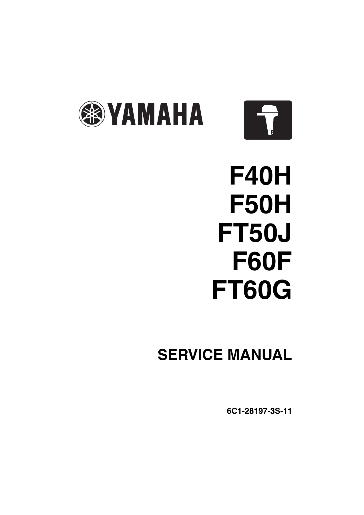
Yamaha F40H F50H FT50J F60F FT60G Service Repair Manual
This is the full Yamaha service manual prepared for the F40H, F50H, FT50J, F60F and FT60G four-stroke outboard motors. It is the second edition, published June 2014 under document number 6C1-28197-3S-11, and covers the multipoint electronic fuel injected, 4-stroke, L4, SOHC, 8-valve 996 cmΒ³ (60.8 cu. in) engine platform shared across these models. Every chapter a technician needs to diagnose, disassemble, repair, reassemble and maintain these outboards is included, from the top cowling down to the lower unit and PTT system.
File Details
- Manual type: Service / workshop manual
- Brand: Yamaha
- Models covered: F40H, F50H, FT50J, F60F, FT60G
- Document number: 6C1-28197-3S-11
- Edition: 2nd Edition, June 2014
- Language: English
- Format: PDF
- Approximate page count: 506 pages
Chapters Covered
- General Information β safety while working, manual format, abbreviations, lubricants, sealants, special service tools
- Specifications β model data, dimensions and weight, performance, power unit, lower unit, bracket unit, fuel and oil, battery, PTT fluid, electrical, fuel system, tightening torques
- Technical Features and Description β electronic control system, ECM, electronic fuel injection control, ignition timing control, engine speed control, ISC valve control, fail-safe, Y-COP, tilt limiter, fuel, lubrication, cooling, intake and exhaust, PTT unit
- Rigging Information β outboard motor mounting, rigging grommet, battery cable, shift and throttle cable, main wire harness, gauge harness, tiller handle, optional water pressure and speed sensors, tilt limiter, Y-COP, battery installation, system diagrams, propeller selection
- Troubleshooting β YDIS diagnostics, trouble codes, power unit, PTT unit and lower unit fault-finding
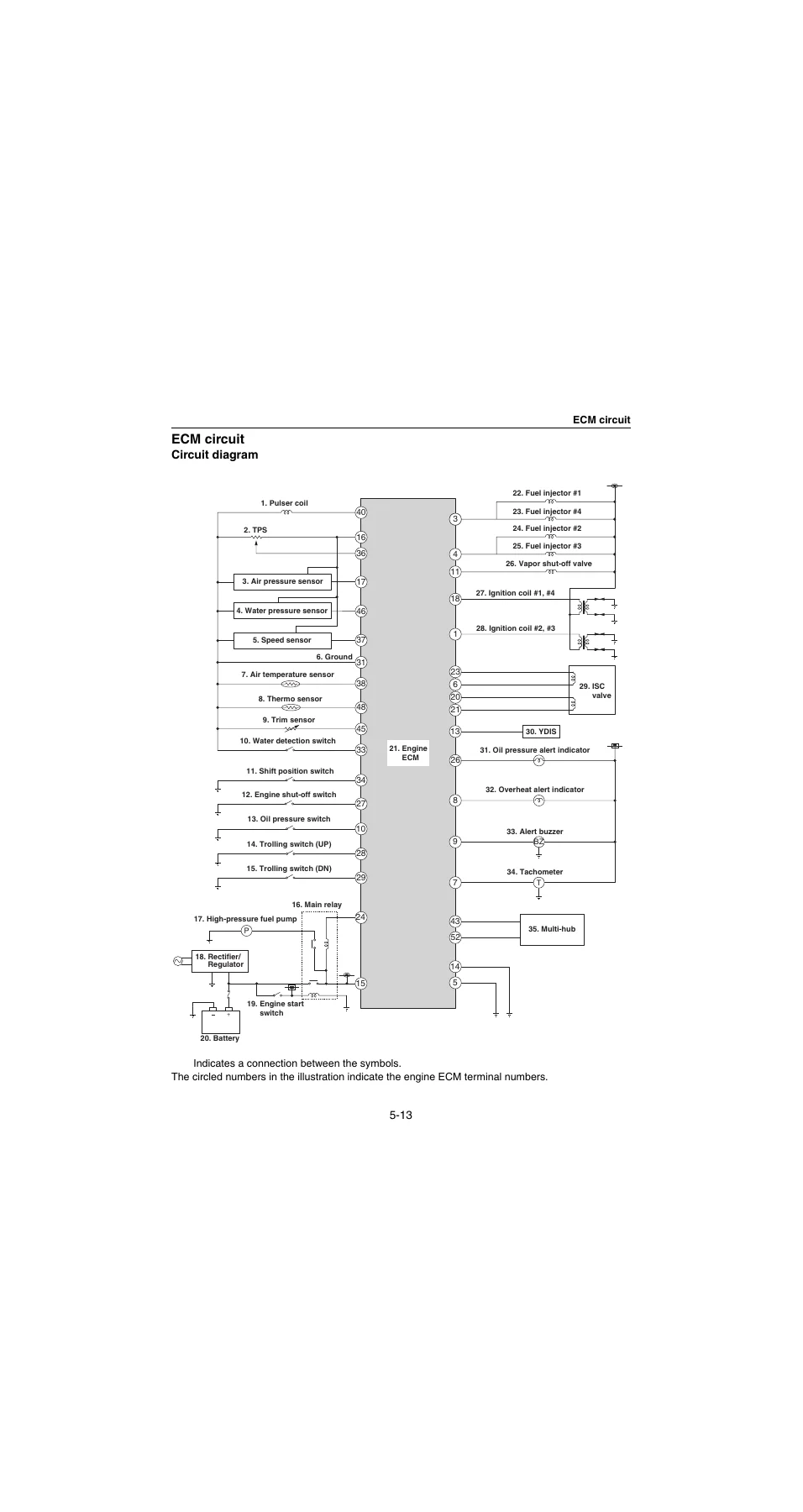
- Electrical System β ECM circuit, component testing, main relay, TPS, ISC valve, oil pressure switch, alert indicators and buzzer, fuel injector, high-pressure fuel pump, vapor shut-off valve, lighting coil, Rectifier/Regulator, ignition, pulser coil, sensors, switches, starter relay, starter motor, Y-COP, Digital Network Gauge sensors, PTT system
- Fuel System β fuel hose routing, blowby and vapor hoses, cooling water hoses, pressure reduction, quick connector, fuel pressure, pressure regulator, fuel filter assembly, fuel pump assembly, intake silencer, intake manifold, fuel injectors, throttle link rod, vapor separator, high-pressure fuel pump
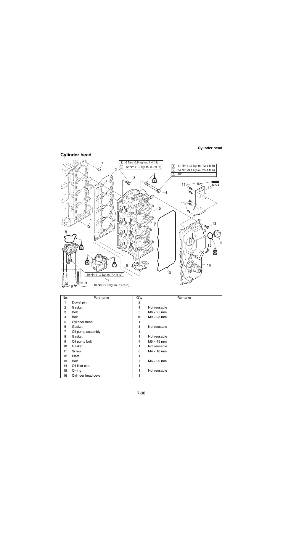
- Power Unit β compression, oil pressure, pulser coil air gap, valve clearance, power unit removal/installation, flywheel magneto, timing belt, ECM, starter motor, Rectifier/Regulator, ignition coil, spark plug, wire harness, shift bracket, cylinder head, camshaft, valve, exhaust cover, cylinder block
- Lower Unit β lower unit removal, water pump, propeller shaft housing, drive shaft, lower case, shimming procedures
- Bracket Unit β friction plate, tiller handle, electrical multifunction components, shift rod, bottom cowling, upper case, oil pan, exhaust manifold, steering arm, clamp and swivel bracket, hydro tilt, PTT unit, PTT motor, gear pump, PTT cylinder
- Maintenance β predelivery checks, general periodic maintenance, interval charts, greasing points, fluid levels, gear oil, propeller, impeller
- Index and Appendix β wiring diagrams, shim selection tables and charts
Across roughly 506 pages, this Yamaha F40H F50H FT50J F60F FT60G service manual gives a technician the full factory picture of how these four-stroke outboards are built and serviced. It opens with the safety and tooling groundwork, moves into model-by-model specifications with torque values, clearances and service limits, then walks through every major assembly in exploded view form. The electrical and fuel chapters cover the electronic control system end to end β ECM inputs and outputs, sensor testing, injector and pump diagnostics, relay and switch checks, YDIS trouble codes and the fail-safe behavior that shapes real-world fault-finding. The power unit chapter supports full top-end and bottom-end work: compression and oil pressure checks, valve clearance adjustment, timing belt replacement, cylinder head and camshaft service, piston and crankshaft measurement and bearing selection. The lower unit chapter includes shimming workflows, gear backlash measurement and shim selection charts so gearcase rebuilds can be brought back into specification rather than guessed at.
Complete PDF Bookmark Tree
Complete Bookmarks
The complete bookmarks in the βYamaha F40H F50H FT50J F60F FT60G Service Repair Manual 2014β are as follows:
+Contentsp. 3
+General informationp. 5
+!Safety while workingp. 6
Rotating partp. 6
Hot partp. 6
Electric shockp. 6
Propellerp. 6
Handling of gasolinep. 6
Ventilationp. 6
Self-protectionp. 7
Working with cranep. 7
Handling of gas torchp. 7
Part, lubricant, and sealantp. 7
Handling of sealantp. 8
Special service toolp. 8
Tightening torquep. 8
Non-reusable partp. 8
Disassembly and assemblyp. 8
+How to use this manualp. 9
Manual formatp. 9
Abbreviationp. 10
+Lubricant, sealant, and thread locking agentp. 11
Special service toolp. 13
+Specificationp. 24
+Model featurep. 26
General featurep. 26
Model name designationp. 27
Serial numberp. 28
+Model datap. 29
Dimension and weightp. 29
Performancep. 30
Power unitp. 31
Lower unitp. 31
Bracket unitp. 32
Fuel and oil requirementp. 33
Battery requirementp. 33
PTT fluid requirementp. 33
+Electrical system technical datap. 34
Ignition timing control systemp. 34
Fuel injection control systemp. 34
Engine speed control systemp. 35
PTT systemp. 35
Charging systemp. 35
Starting systemp. 35
Y-COPp. 36
Gauge/sensorp. 36
+Fuel system technical datap. 37
+Power unit technical datap. 38
Power unitp. 38
Cylinder head assemblyp. 38
Crankcase assemblyp. 39
+Lower unit technical datap. 41
Lower unit assembly (F40H, F50H, F60F)p. 41
Lower unit assembly (FT50J, FT60G)p. 41
+Bracket unit technical datap. 42
+Specified tightening torquep. 43
Rigging informationp. 43
Electrical systemp. 43
Fuel systemp. 43
Power unitp. 44
Lower unit (F40H, F50H, F60F)p. 46
Lower unit (FT50J, FT60G)p. 47
Tiller handle modelp. 47
Bracket unitp. 48
PTT unitp. 49
General tightening torquep. 50
+Technical feature and descriptionp. 51
Major changesp. 52
+Electronic control systemp. 53
Engine ECM componentsp. 55
ECMp. 56
Electronic fuel injection controlp. 57
Ignition timing controlp. 59
Engine speed controlp. 60
ISC valve controlp. 61
Alert indicator, alert buzzer controlp. 61
Fail-safep. 61
+Additional featuresp. 63
Y-COP (standard for European market and optional for Oceanian market)p. 63
Tilt limiter (optional)p. 64
+Fuel systemp. 65
+Lubrication systemp. 67
+Cooling systemp. 69
+Intake and exhaust systemp. 71
Intake and exhaust diagramp. 71
+PTT unitp. 72
Trim-up and tilt-up functionp. 72
Trim-down and tilt-down functionp. 73
Stationary conditionp. 74
Shock-absorbing functionp. 74
+Rigging informationp. 76
+Important reminder on riggingp. 78
Outboard motor mounting instructionsp. 78
+Crate handlingp. 79
Crate top cover pictograph descriptionp. 79
+Uncratingp. 80
+External dimensionsp. 82
F40HET, F50HET, F60FETp. 82
F50HEDp. 83
F50HEHT, F60FEHTp. 84
F50HEHDp. 85
FT50JET, FT60GETp. 86
FT60GEHTp. 87
FT60GEHDp. 88
Clamp bracket dimensionsp. 89
+Outboard motor mountingp. 90
Installing the outboard motorp. 90
Outboard motor mounting heightp. 91
+Rigging grommet mountingp. 92
Rigging grommet descriptionp. 92
Installing the battery cablep. 92
Installing the shift cable and throttle cablep. 93
Installing the main wire harnessp. 95
Installing the Digital Network Gauge harnessp. 95
Installing the conventional gauge harnessp. 96
Installing the rigging grommetp. 96
+Tiller handlep. 96
Installing the tiller handlep. 96
+Optional equipmentp. 98
Installing the water pressure sensor (Digital Network Gauge)p. 98
Installing the speed sensor (Digital Network Gauge)p. 100
Installing the tilt limiterp. 101
Setting the tilt limiterp. 104
Deactivating the tilt limiterp. 105
+Y-COP (standard for European market and optional for Oceanian market)p. 105
Installing Y-COPp. 105
Registering the remote control receiver ID to the ECMp. 106
Battery installationp. 107
+System diagramp. 108
Single engine application (Digital Network Gauge)p. 108
Single engine application (conventional gauge)p. 110
+Rigging recommendationp. 112
Battery cable lengthp. 112
+Propeller selectionp. 113
Propeller sizep. 113
Selectionp. 113
+Troubleshootingp. 117
+YDISp. 118
Basic componentsp. 118
Functionp. 119
Connecting the communication cablep. 122
+Outboard motor troubleshootingp. 123
Troubleshooting procedurep. 123
Troubleshooting the power unit using the YDISp. 123
Trouble code and checking stepp. 125
Troubleshooting the power unit (trouble code not detected)p. 127
Troubleshooting the PTT unitp. 132
Troubleshooting the lower unitp. 133
+Electrical systemp. 134
+Electrical component and wire harness routingp. 136
Portp. 136
Starboardp. 139
Frontp. 141
Topp. 143
Bottom cowlingp. 144
Tiller handlep. 146
+ECM circuitp. 148
Circuit diagramp. 148
ECM coupler layoutp. 150
+Checking the electrical componentp. 151
Using the YDISp. 151
Measuring the peak voltagep. 151
Using the digital testerp. 151
+Engine control unit and componentp. 152
Checking the main relayp. 152
Checking the engine ECM circuitp. 153
Checking the TPSp. 154
Checking the ISC valvep. 154
Checking the oil pressure switchp. 154
Checking the alert indicator (tiller handle model)p. 155
Checking the alert buzzerp. 156
Checking the trolling switch (tiller handle model)p. 156
+Fuel control unit and componentp. 156
Checking the water detection switchp. 156
Checking the fuel injectorp. 157
Checking the high-pressure fuel pumpp. 157
Checking the vapor shut-off valvep. 158
+Charging unit and componentp. 159
Checking the lighting coil (stator assembly)p. 159
Checking the Rectifier/Regulatorp. 160
+Ignition unit and componentp. 161
Checking the ignition sparkp. 161
Checking the spark plug wirep. 161
Checking the ignition coilp. 161
Checking the pulser coilp. 162
Checking the intake air temperature sensorp. 162
Checking the intake air pressure sensorp. 162
Checking the thermo sensorp. 163
Checking the shift position switchp. 163
Checking the engine shut-off switchp. 164
+Starting unit and componentp. 164
Checking the starter relayp. 164
Checking the engine start switchp. 165
+Y-COP (standard for European market and optional for Oceanian market)p. 166
Checking Y-COPp. 167
Checking the buzzerp. 167
Checking the Y-COP main wire harnessp. 167
Checking the button cell batteryp. 168
+Starter motorp. 170
Removing the starter motorp. 172
Checking the starter motor pinionp. 172
Disassembling the starter motorp. 172
Checking the armature (starter motor)p. 174
Checking the brush holderp. 174
Assembling the starter motorp. 175
Installing the starter motorp. 176
+Digital Network Gauge sensorp. 177
Checking the water pressure sensorp. 177
Checking the speed sensorp. 177
+PTT systemp. 178
Checking the PTT relayp. 178
Checking the PTT switch (on bottom cowling)p. 179
Checking the trim sensorp. 180
Checking the tilt limiterp. 180
+Fuel systemp. 182
+Hose routingp. 184
Fuel hosep. 184
Blowby hose, vapor gas hose, and pressure regulator hosep. 185
Cooling water hosep. 186
+Fuel systemp. 187
Reducing the fuel pressurep. 187
Disconnecting the quick connectorp. 187
Measuring the fuel pressurep. 188
Checking the pressure regulatorp. 188
+Fuel filter assemblyp. 190
Removing the fuel filter assemblyp. 192
Checking the fuel jointp. 192
Checking the fuel filter assemblyp. 193
Disassembling the fuel filter assemblyp. 193
Checking the fuel filter elementp. 194
Checking the fuel cup assemblyp. 194
Checking the primer pumpp. 194
Assembling the fuel filter assemblyp. 194
Installing the fuel filter assemblyp. 194
+Fuel pump assemblyp. 196
Removing the fuel pump assemblyp. 198
Checking the fuel pump assemblyp. 198
Disassembling the fuel pump assemblyp. 199
Checking the diaphragm and valvep. 200
Checking the fuel strainerp. 200
Assembling the fuel pump assemblyp. 200
Installing the fuel pump assemblyp. 201
+Intake silencerp. 203
Removing the intake silencerp. 204
Installing the intake silencerp. 204
+Intake manifold and fuel injectorp. 205
Removing the fuel injectorp. 207
Checking the fuel rail and fuel injectorsp. 207
Removing the intake manifoldp. 208
Checking the intake manifoldp. 209
Checking the ISC valvep. 209
Checking the throttle bodyp. 209
Checking the TPSp. 209
Checking the intake air pressure/ temperature sensorp. 209
Installing the intake manifoldp. 209
Installing the fuel injectorp. 211
+Throttle link rodp. 213
Removing the throttle linkp. 214
Installing the throttle linkp. 214
Adjusting the throttle link rodp. 215
+Vapor separator and vapor shut-off valvep. 217
Draining the fuelp. 219
Removing the vapor shut-off valvep. 219
Removing the vapor separatorp. 219
Checking the vapor shut-off valvep. 221
Installing the vapor separatorp. 221
Installing the vapor shut-off valvep. 222
+Vapor separator and high-pressure fuel pumpp. 224
Disassembling the vapor separatorp. 226
Checking the high-pressure fuel pumpp. 227
Checking the vapor separatorp. 227
Adjusting the float heightp. 227
Assembling the vapor separatorp. 227
+Power unitp. 231
+Power unit (check and adjustment)p. 234
Checking the compression pressurep. 234
Checking the oil pressurep. 234
Checking the pulser coil air gapp. 234
Adjusting the pulser coil air gapp. 235
Checking the valve clearancep. 235
Adjusting the valve clearancep. 237
+Power unit assemblyp. 238
Removing the power unitp. 240
Installing the power unitp. 242
+Flywheel magneto and timing beltp. 247
Removing the flywheel magnetop. 249
Removing the stator assemblyp. 249
Removing the timing belt and sprocketp. 250
Checking the timing belt and sprocketp. 251
Installing the sprocket and timing beltp. 251
Installing the stator assemblyp. 253
Installing the flywheel magnetop. 254
+Engine ECM and starter motorp. 255
Removing the starter motorp. 257
Removing the starter relayp. 257
Installing the starter relayp. 258
Installing the starter motorp. 258
+Rectifier/Regulator and ignition coil and spark plugp. 260
Removing the Rectifier/Regulator and ignition coilp. 261
Checking the spark plugp. 261
Installing the ignition coil and Rectifier/Regulatorp. 261
+Wire harnessp. 263
Removing the wire harnessp. 266
Installing the wire harnessp. 267
Shift bracketp. 270
+Cylinder headp. 271
Removing the cylinder headp. 272
Disassembling the oil pumpp. 272
Checking the oil pumpp. 272
Assembling the oil pumpp. 273
Checking the cylinder head boltp. 273
Installing the cylinder headp. 273
+Camshaft and valvep. 276
Disassembling the cylinder headp. 278
Checking the cylinder headp. 279
Checking the valve springp. 279
Checking the valvep. 280
Checking the valve guidep. 280
Replacing the valve guidep. 281
Checking the valve seatp. 281
Refacing the valve seatp. 282
Checking the rocker arm and rocker arm shaftp. 284
Checking the camshaftp. 284
Checking the cylinder head anodep. 285
Assembling the cylinder headp. 285
+Exhaust coverp. 288
Removing the exhaust coverp. 290
Removing the thermo sensorp. 290
Removing the oil pressure switchp. 290
Removing the oil filterp. 290
Checking the exhaust cover anodep. 291
Checking the thermostatp. 291
Installing the oil filterp. 291
Installing the oil pressure switchp. 291
Installing the thermo sensorp. 292
Installing the exhaust coverp. 292
+Cylinder blockp. 294
Disassembling the cylinder blockp. 295
Checking the piston diameterp. 295
Checking the cylinder borep. 296
Piston clearance checkp. 296
Checking the piston ringp. 296
Checking the piston ring end gapp. 296
Checking the piston ring groovep. 297
Checking the piston ring side clearancep. 297
Checking the piston pin bossp. 297
Checking the piston pinp. 298
Checking the connecting rod small end inside diameter and big end inside diameterp. 298
Checking the connecting rod big end side clearancep. 298
Checking the crankshaftp. 298
Checking the crankshaft pin oil clearancep. 299
Selecting the crankshaft pin bearingp. 300
Checking the crankshaft journal oil clearancep. 301
Selecting the crankshaft journal bearingp. 302
Assembling the cylinder blockp. 303
+Lower unitp. 306
+Lower unit (F40H, F50H, F60F, L-transom model)p. 310
Removing the lower unitp. 312
Checking the propellerp. 312
Checking the lower unit anodep. 312
+Lower unit (F50H, F60F, X-transom model)p. 313
Removing the lower unitp. 315
Checking the propellerp. 315
Checking the lower unit anodep. 315
+Water pump (F40H, F50H, F60F)p. 316
Removing the water pumpp. 318
Disassembling the water pumpp. 318
Disassembling the oil seal housingp. 318
Checking the water pumpp. 318
Assembling the oil seal housingp. 319
Assembling the water pumpp. 319
+Propeller shaft housing (F40H, F50H, F60F)p. 320
Removing the propeller shaft housing assemblyp. 321
Disassembling the propeller shaft assemblyp. 321
Disassembling the propeller shaft housing assemblyp. 321
Checking the propeller shaftp. 322
Checking the dog clutchp. 322
Checking the propeller shaft housingp. 322
Checking the reverse gearp. 322
Assembling the propeller shaft assemblyp. 322
Assembling the propeller shaft housing assemblyp. 322
+Drive shaft and lower case (F40H, F50H, F60F)p. 324
Removing the drive shaftp. 326
Removing the shift rodp. 326
Disassembling the drive shaftp. 326
Disassembling the forward gearp. 326
Disassembling the shift rodp. 327
Disassembling the lower casep. 327
Checking the pinionp. 328
Checking the forward gearp. 328
Checking the drive shaftp. 328
Checking the lower casep. 328
Assembling the forward gearp. 328
Assembling the drive shaftp. 328
Assembling the shift rodp. 328
Assembling the lower casep. 329
Installing the shift rodp. 330
Installing the drive shaftp. 331
Installing the propeller shaft housing assemblyp. 331
Installing the water pumpp. 332
Checking the lower unit for air leakagep. 332
Installing the lower unit (L-transom model)p. 333
Installing the lower unit (X-transom model)p. 334
+Shimming (F40H, F50H, F60F)p. 336
Shimming workflowp. 336
Shimming check sheetp. 337
Measuring the forward gear backlash and reverse gear backlash before disassemblyp. 339
Shimmingp. 342
Shim locationp. 342
Selecting the pinion shim (T3)p. 343
Measuring the forward gear backlashp. 345
Adjusting the forward gear shim thickness (T1)p. 345
Measuring the reverse gear backlashp. 346
Adjusting the reverse gear shim thickness (T2)p. 347
+Lower unit (FT50J, FT60G, L-transom model)p. 349
Removing the lower unitp. 351
Checking the propellerp. 351
Checking the lower unit anodep. 351
+Lower unit (FT50J, FT60G, X-transom model)p. 352
Removing the lower unitp. 354
Checking the propellerp. 354
Checking the lower unit anodep. 354
+Water pump and shift rod (FT50J, FT60G)p. 355
Removing the water pump and shift rodp. 357
Disassembling the water pumpp. 357
Disassembling the oil seal housingp. 358
Disassembling the shift rodp. 358
Checking the water pump and shift rodp. 358
Assembling the oil seal housingp. 358
Assembling the water pumpp. 359
+Propeller shaft housing (FT50J, FT60G)p. 360
Removing the propeller shaft housing assemblyp. 362
Disassembling the propeller shaft assemblyp. 362
Disassembling the propeller shaft housing assemblyp. 363
Checking the propeller shaftp. 363
Checking the dog clutchp. 363
Checking the propeller shaft housingp. 363
Checking the reverse gearp. 363
Assembling the propeller shaft assemblyp. 363
Assembling the propeller shaft housing assemblyp. 364
+Drive shaft and lower case (FT50J, FT60G)p. 366
Removing the drive shaftp. 367
Disassembling the drive shaftp. 367
Disassembling the forward gearp. 367
Disassembling the lower casep. 367
Checking the pinionp. 368
Checking the forward gearp. 368
Checking the drive shaftp. 368
Checking the lower casep. 369
Assembling the forward gearp. 369
Assembling the drive shaftp. 369
Assembling the shift rodp. 369
Assembling the lower casep. 370
Installing the drive shaftp. 371
Installing the propeller shaft housing assemblyp. 372
Installing the shift rodp. 373
Installing the water pumpp. 373
Checking the lower unit for air leakagep. 374
Installing the lower unit (L-transom model)p. 374
Installing the lower unit (X-transom model)p. 376
+Shimming (FT50J, FT60G)p. 377
Shimming workflowp. 377
Shimming check sheetp. 378
Measuring the forward gear backlash before disassemblyp. 380
Shimmingp. 383
Shim locationp. 383
Selecting the pinion shim (T3)p. 384
Measuring the forward gear backlashp. 386
Adjusting the forward gear shim thickness (T1)p. 386
+Bracket unitp. 389
+Friction platep. 392
Removing the friction platep. 394
Disassembling the friction platep. 394
Assembling the friction platep. 394
Installing the friction plate assemblyp. 395
+Tiller handlep. 396
Disassembling the tiller handlep. 399
Assembling the tiller handlep. 400
+Electrical component (multifunction)p. 404
Disassembling the electrical component (multifunction)p. 405
Assembling the electrical component (multifunction)p. 405
+Shift rod and shift bracketp. 407
Disassembling the shift rodp. 408
Assembling the shift rodp. 408
+Bottom cowlingp. 409
Disassembling the bottom cowlingp. 412
Assembling the bottom cowlingp. 412
+Upper case and mountp. 415
Removing the upper casep. 417
Installing the upper case (F40H, F50H, F60F)p. 418
Installing the upper case (FT50J, FT60G)p. 419
+Upper casep. 421
Disassembling the upper casep. 422
Checking the drive shaft bushingp. 422
Assembling the upper casep. 422
+Oil pan and exhaust manifoldp. 424
Disassembling the oil pan and exhaust manifoldp. 426
Checking the oil pan and exhaust manifoldp. 427
Checking the oil strainerp. 427
Assembling the oil pan and exhaust manifoldp. 427
+Steering armp. 430
Removing the steering armp. 431
Installing the steering armp. 431
+Clamp bracket and swivel bracketp. 434
Removing the clamp bracketp. 436
Checking the clamp bracket anodep. 436
Installing the clamp bracketp. 436
Adjusting the trim sensorp. 438
+Hydro tiltp. 440
Removing the hydro tilt assemblyp. 441
Checking the hydro tiltp. 441
Checking the hydro tilt anodep. 441
Installing the hydro tilt assemblyp. 441
+PTT unitp. 442
Removing the PTT unitp. 443
Checking the PTT unit anodep. 443
Bleeding the PTT unitp. 443
Installing the PTT unitp. 445
+PTT motorp. 446
Removing the PTT motorp. 447
Disassembling the PTT motorp. 447
Checking the armature (PTT motor)p. 448
Checking the brushp. 448
Assembling the PTT motorp. 449
Installing the PTT motorp. 450
+PTT gear pumpp. 451
Disassembling the gear pump assemblyp. 454
Checking the gear pumpp. 454
Assembling the gear pump housingp. 455
+PTT cylinderp. 457
Disassembling the trim cylinderp. 459
Disassembling the tilt cylinderp. 459
Disassembling the trim and tilt ram assemblyp. 459
Checking the PTT cylinder and pistonp. 460
Checking the absorber valvep. 460
Assembling the trim and tilt ram assemblyp. 460
Assembling the tilt cylinderp. 461
Assembling the trim cylinderp. 462
+Maintenancep. 464
+Outlinep. 466
Maintenance interval chart 1p. 466
Maintenance interval chart 2p. 468
+Predelivery checkp. 469
Checking the batteryp. 469
Checking the cooling water pilot holep. 470
Checking the engine oil levelp. 470
Checking the main switch/stop switchp. 470
Checking the fuel linep. 471
Checking the gear oil levelp. 471
Checking the gear shift and throttle operation (remote control model)p. 471
Checking the gear shift and throttle operation (tiller handle model)p. 472
Checking the outboard motor mounting heightp. 472
Checking the power trim and tilt unitp. 472
Checking the hydro tilt unitp. 472
Checking the steering systemp. 472
Checking the throttle cable and shift cable (remote control model)p. 473
Checking the throttle cable and shift cable (tiller handle model)p. 473
Test runp. 473
Break-inp. 473
After test runp. 474
+General periodic maintenancep. 474
Checking the anodep. 474
Checking the batteryp. 474
Checking the cooling water inletp. 474
Checking the cooling water pilot holep. 475
Checking the engine idle speed/ noisep. 475
Changing the engine oil using an oil changerp. 475
Changing the engine oil by removing the drain boltp. 476
Checking the engine oil levelp. 478
Replacing the oil filterp. 478
Checking the exhaust guide/exhaust manifoldp. 478
Checking the main switch/stop switchp. 478
Checking the fuel filterp. 478
Checking the fuel pumpp. 478
Checking for fuel/engine oil leakagep. 479
Changing the gear oilp. 479
Checking the gear oil levelp. 480
Greasing pointsp. 480
Checking the propeller/propeller nut/ cotter pinp. 481
Checking the PTT fluid levelp. 481
Checking the power trim and tilt unit operationp. 481
Checking the hydro tilt unit operationp. 482
Adjusting the shift link/shift cablep. 482
Checking the spark plugp. 482
Checking the timing beltp. 482
Replacing the timing beltp. 482
Checking the thermostatp. 482
Adjusting the throttle link/throttle cablep. 482
Checking the cowling lock leverp. 482
Checking the valve clearancep. 483
Checking the impeller/water pump housingp. 483
Indexp. 484
+Appendixp. 491
+Wiring diagramp. 492
How to use the wiring diagramp. 492
+Shim selection table and chart (F40H, F50H, F60H)p. 504
Pinion shim (T3) selection tablep. 504
Ignition unit (hydro tilt model)p. 502
Engine control unit and fuel unit (PTT model)p. 497
Charging unit, starting unit, and PTT unit (PTT model without tilt limiter)p. 499
Charging unit, starting unit, and PTT unit (PTT model with tilt limiter)p. 500
Engine control unit and fuel unit (hydro tilt model)p. 501
Ignition unitp. 498
Control unitp. 503
Forward gear shim (T1) selection chart (F40H, F50H, F60F)p. 505
Reverse gear shim (T2) selection chart (F40H, F50H, F60F)p. 505
+Shim selection table and chart (FT50J, FT60G)p. 506
Pinion shim (T3) selection tablep. 506
Forward gear shim (T1) selection chart (FT50J, FT60G)p. 506
Why This Manual Matters
Working on a fuel-injected four-stroke outboard without the correct procedures and specifications leads to mis-timed ignition, wrong valve clearances, incorrect bearing selection and gearcases that whine or fail early. This manual removes that guesswork. It tells you the tightening torque, the service limit, the measuring point, the testing sequence and the correct assembly order for each job β from a simple oil and filter change to a full cylinder head rebuild or a lower unit re-shim. It is written for the F40H, F50H, FT50J, F60F and FT60G specifically, so the values and diagrams line up with the machine in front of you rather than a generic outboard.
Jobs This Manual Supports
- Routine servicing: engine oil and filter, gear oil, spark plugs, anodes, impeller, thermostat, fuel filter
- Electronic fuel injection diagnosis and component replacement
- Ignition system testing and coil / pulser coil service
- Valve clearance adjustment and cylinder head rebuild
- Timing belt replacement with correct sprocket alignment
- Piston, ring, connecting rod and crankshaft measurement and bearing selection
- Lower unit disassembly, gear backlash measurement and shimming
- PTT unit, PTT motor, gear pump and cylinder service
- Steering, clamp bracket, swivel bracket and hydro tilt work
- YDIS trouble code retrieval and fault isolation
- Rigging: cables, harnesses, gauges, sensors and Y-COP registration
Get It Instantly
This Yamaha F40H F50H FT50J F60F FT60G service repair manual is delivered as an instant PDF download β no shipping, no waiting. Read it on a laptop, tablet or phone in the workshop, or print the pages you need and take them to the bench. Whether you are servicing your own outboard or running a marine repair shop, this manual puts the correct procedure and the correct specification in front of you at the moment you need them.
Reviews
There are no reviews yet.