Description
Tohatsu MFS 25B 30B 4-Stroke Outboard Service Manual
This Tohatsu MFS 25B 30B 4-Stroke Outboard Service Manual provides the complete inspection, service and repair information for the 25 and 30 horsepower four-stroke outboard motors. Published in 2012, this 355-page workshop manual covers every major system on these engines, from routine maintenance and pre-delivery inspection to full power unit and lower unit disassembly. Whether you are a professional marine technician or a boat owner performing your own maintenance, this Tohatsu outboard service manual delivers the procedures, specifications and diagrams needed to keep these engines running reliably.
File Details
- Manual Type: Service Manual
- Brand: Tohatsu
- Model: MFS 25B, MFS 30B
- Publication Number: OB No. 003-21054-2 12-04 NB
- Language: English
- Page Count: 355
- File Format: PDF
- Date: 2012
Chapters Covered
- 1. Service Information β Identification, Work Safety, Tools and Instruments, Pre-delivery Inspection, Break-in Operation, Test Run
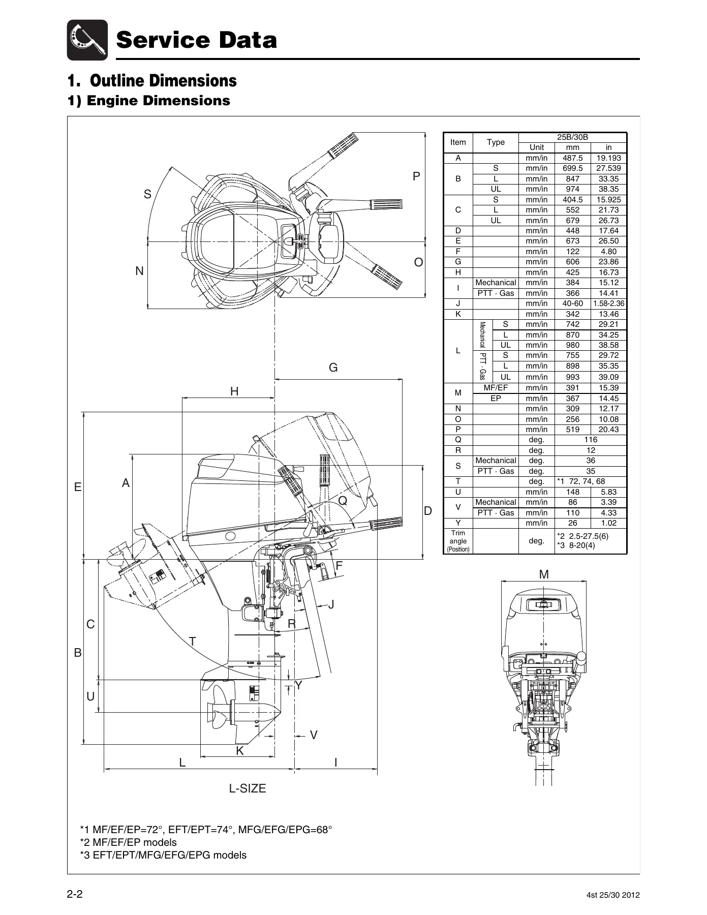
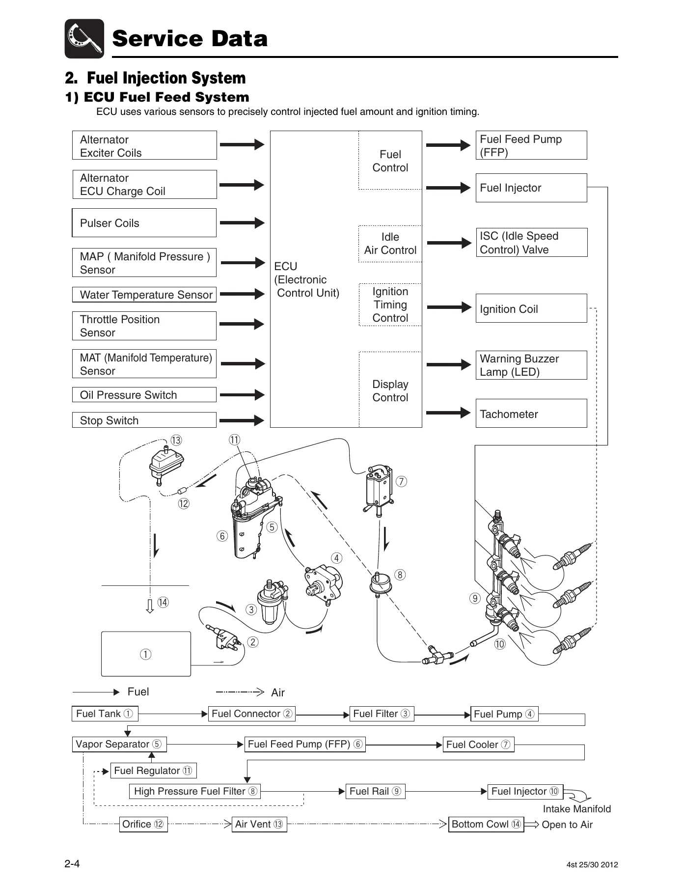
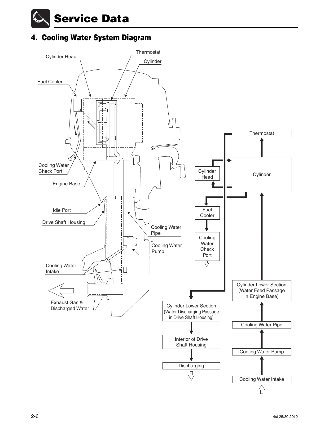
- 2. Service Data β Outline Dimensions, Fuel Injection System, Engine Lubrication and Cooling Diagrams, Specifications, Maintenance Data, Tightening Torque Data, Sealant Application Locations
- 3. Maintenance β Special Tools, Inspection Schedule, Inspection Items including engine oil, gear oil, water pump, timing belt, spark plugs, compression pressure, valve clearance, throttle cable, shift lever, PTT unit, anodes, thermostat, battery, greasing points
- 4. Fuel System (Fuel Injection) β Piping Arrangement, Parts Layout, ECU System, Sensors and Actuators, Fuel Injection Control, Ignition System, Fuel Feed System Components, Inspection Items
- 5. Power Unit β Parts Layout, Compression Pressure, Oil Pressure, Valve Clearance, Timing Belt, Cylinder Head, Valves, Cam Shaft, Oil Pump, Piston, Crankshaft, Recoil Starter
- 6. Lower Unit β Gear Case, Drive System and Water Pump, Shift, Propeller Shaft, Clutch Cam, Drive Shaft, Forward and Pinion Gears, Backlash Setting
- 7. Bracket β Drive Shaft Housing, Swivel Bracket, Clamp Bracket, Power Trim and Tilt, Tiller Handle, Bottom Cowl, Shift
- 8. Electrical System β Ignition System, Fuel Control System, Starting System, Battery Charging System, ECU Coupler
- 9. Troubleshooting β Power Unit, PTT Unit, 3AC Diagnosis System
- 10. Accessories β Remote Control Components, Meters and Battery Installation, Warning Indication
- 11. Wiring Diagram β Wiring Chart, MF/MFG, EF/EFG/EFT, EP/EPG/EPT Models
The Tohatsu MFS 25B 30B service manual opens with a complete chapter on service information covering engine serial number identification, work safety procedures, special tools and measuring instruments, pre-delivery inspection checklist, break-in operation requirements, and post-test-run checks. This foundation ensures every subsequent repair is performed safely and correctly, with the proper tools and torque values in hand.
Complete Engine and System Coverage
At 355 pages, this 4-stroke outboard workshop manual goes far beyond basic maintenance. The Power Unit chapter alone spans dozens of procedures: removing and installing the power unit, timing belt removal and replacement with correct pulley alignment, cylinder head disassembly and valve inspection, camshaft measurement and installation, oil pump inspection, piston and connecting rod assembly, crankshaft runout measurement, and bearing oil clearance checks using plasti-gauge. Every measurement includes standard values and functional limits, so you know exactly when a component can be reused and when it must be replaced.
The Lower Unit chapter provides the complete disassembly and assembly sequence for the gear case, water pump, propeller shaft, clutch cam, drive shaft, and forward and pinion gears. Critical settings such as pinion gear height and forward gear backlash are covered in detail, with shim adjustment tables and special tool references. This is information you will not find in a generic repair guide β it is specific to the Tohatsu MFS 25B and 30B gear case design.
The Bracket chapter covers the drive shaft housing, swivel bracket, clamp bracket, power trim and tilt unit, gas shock absorber, and tiller handle. For PTT-equipped models, the manual walks through motor removal, pump and valve inspection, tilt cylinder assembly, air purging procedures, and PTT solenoid and switch testing. Tiller handle models get dedicated coverage for throttle cable installation and co-pilot plate adjustment.
Fuel Injection and Electrical Systems
The Fuel System chapter is particularly important for these electronic fuel injection models. It explains the ECU system configuration, sensor inputs, actuator outputs, fuel injection timing and correction strategies, ignition control, and the complete fuel feed system including the low-pressure mechanical pump, vapor separator, fuel cooler, high-pressure filter, fuel rail, and injectors. Step-by-step inspection procedures cover fuel pressure measurement, fuel regulator testing, vapor separator disassembly and float height adjustment, and ISC valve inspection.
The Electrical System chapter provides component layouts and inspection procedures for the ignition system, fuel control system, starting system, and battery charging system. You will find resistance values for ignition coils, pulser coils, alternator coils, injectors, ISC valve, and various sensors. The ECU coupler terminal chart identifies every pin, wire color, and function, making electrical troubleshooting straightforward.
Complete PDF Bookmark Tree
Complete Bookmarks
The complete bookmarks in the βTohatsu MFS 25B 30B 4-Stroke Outboard Service Manual 2012β are as follows:
+Introductionp. 3
+Before reading this manualp. 3
About this manualp. 4
+Description of Pictographp. 6
1. Service Informationp. 7
2. Securing of Work Safety 1-2p. 7
3. Tools and Instruments 1-5p. 7
4. Pre-delivery Inspection 1-9p. 7
5. Break-in Operation 1-15p. 7
6. Test Run 1-15p. 7
+7. Checks After Test Run 1-16p. 7
2. Fuel Injection System 2-4p. 7
3. Engine Lubrication System Diagram 2-5p. 7
4. Cooling Water System Diagram 2-6p. 7
5. Specifications 2-7p. 7
6. Maintenance Data 2-10p. 7
7. Tightening Torque Data 2-18p. 7
+8. Sealant Application Locations 2-20p. 7
2. Inspection Schedule 3-3p. 7
+3. Inspection Items 3-4p. 7
4. Fuel System (Fuel Injection)p. 7
2. Piping Arrangement Diagram 4-3p. 7
3. Parts Layout 4-4p. 7
4. ECU System 4-15p. 7
5. Ignition System 4-25p. 7
6. Components of Fuel Feed System 4-28p. 7
7. Outline of Fuel Injection System 4-30p. 7
+8. Inspection Items 4-31p. 8
2. Parts Layout 5-3p. 8
+3. Inspection Items 5-24p. 8
2. Parts Layout 6-4p. 8
+3. Inspection Items 6-9p. 8
2. PTT Wiring and Layout Diagram 7-3p. 8
3. Parts Layout 7-4p. 8
+4. Inspection Items 7-21p. 9
2. Electrical Component Layout 8-3p. 9
3. Parts Layout 8-8p. 9
4. Ignition System, Ignition Control System 8-16p. 9
5. Fuel Control System 8-21p. 9
6. Starting System 8-23p. 9
7. Battery Charging System 8-26p. 9
+8. ECU Coupler 8-28p. 9
+2. Power Unit 9-3p. 9
State 1: Engine will not start or is a little hard to start. 9-3p. 9
State 2: Full throttle engine revolution speed is low. Engine revolution speed fall off. Engine stalls. 9-9p. 9
State 3: Engine rotation is unstable or hunting occurs in low speed range. 9-16p. 9
+3. PTT Unit 9-19p. 9
State 1: PTT will not operate. 9-19p. 9
State 2: PTT is not capable of sustaining outboard motor. 9-21p. 9
+4. 3AC Diagnosis 9-22p. 9
2. Installation of Meters and Battery 10-6p. 10
+3. Operation 10-9p. 10
INDEXp. 11
+Service Informationp. 13
1. Identification (Engine Serial Number)p. 14
+2. Securing of Work Safetyp. 14
1) Fire Preventionp. 14
2) Ventilationp. 14
3) Protectionp. 14
4) Genuine Partsp. 15
5) Toolsp. 15
6) Recommendations on Servicep. 15
7) Cautions in Disassembling and Assembling Componentsp. 16
+3. Tools and Instrumentsp. 17
1) Test Propellerp. 17
2) Measuring Instrumentsp. 17
3) Special Toolsp. 18
+4. Pre-delivery Inspectionp. 21
1) Steering Handlep. 21
2) Gear Shiftp. 21
3) Engine Oilp. 21
4) Gear Oilp. 22
5) Fuel Linep. 22
6) Riggingp. 22
7) Inspection of PTT Unitp. 22
8) Inspection of Gas Shock Absorberp. 23
9) Inspection of Starting Switch and Stop Switchp. 23
10) Cooling Water Check Portp. 24
11) Idlingp. 25
12) Propeller Selectionp. 25
13) Trim Tabp. 26
5. Break-in Operationp. 27
6. Test Runp. 27
7. Checks After Test Runp. 28
+Service Datap. 29
+1. Outline Dimensionsp. 30
1) Engine Dimensionsp. 30
+2) Transom Boltsp. 31
Mechanical Tilt Modelp. 31
+2. Fuel Injection Systemp. 32
1) ECU Fuel Feed Systemp. 32
3. Engine Lubrication System Diagramp. 33
4. Cooling Water System Diagramp. 34
5. Specificationsp. 35
6. Maintenance Datap. 38
7. Tightening Torque Datap. 46
+8. Sealant Application Locationsp. 48
PTT or Gas Assisted Modelp. 31
+Maintenancep. 51
1. Special Toolsp. 52
2. Inspection Schedulep. 53
+3. Inspection Itemsp. 54
1) Inspection of Top Cowlp. 54
2) Inspection of Fuel System Pipingp. 54
3) Inspection of Fuel Tankp. 55
4) Inspection of Fuel Filterp. 55
5) Replacement of Engine Oilp. 56
6) Replacement of Oil Filterp. 57
7) Inspection of Gear Oil Quantityp. 58
8) Inspection of Water Pumpp. 59
9) Replacement of Gear Oilp. 61
10) Inspection of Gear Case (for Leakage)p. 62
11) Inspection of Timing Beltp. 62
12) Replacement of Timing Beltp. 63
13) Installation of Timing Beltp. 65
14) Inspection of Spark Plugsp. 67
15) Inspection of Compression Pressurep. 68
16) Inspection and Adjustment of Valve Clearancep. 69
17) Throttle Cable Adjustment of Throttle Linkp. 70
18) Inspection of Shift Lever Gear Operationsp. 74
19) Inspection of PTT Unit Operationp. 75
20) Inspection of Gas Assistant Unit Operationsp. 76
21) Inspection of PTT Fluid Quantityp. 76
22) Inspection of Idle Speedp. 77
23) Inspection of Ignition Timingp. 78
24) Inspection of Anodesp. 78
25) Replacement of Anodesp. 79
26) Inspection of Propellerp. 79
27) Inspection of Thermostatp. 80
28) Inspection of Cooling Water Passagep. 81
29) Flushing with Waterp. 82
30) Inspection of Batteryp. 83
31) Greasing Pointsp. 84
+Fuel System (Fuel Injection)p. 87
1. Special Toolsp. 88
+2. Piping Arrangement Diagramp. 89
Fuel Hose, Vent Hose, Breather Hose, Cooling Water Hosep. 89
+3. Parts Layoutp. 90
Fuel Pump, Fuel Rail, Vapor Separatorp. 90
Fuel Pump, Fuel Rail, Vapor Separatorp. 92
Intake Manifoldp. 94
Magneto & ECUp. 96
Electric Partsp. 98
Separate Fuel Tankp. 100
+4. ECU Systemp. 101
1) Sensorsp. 102
2) Actuatorsp. 104
3) Control System (ECU)p. 105
1) Fuel Injection Timingp. 108
2) Starting Fuel Increase Correctionp. 108
3) Acceleration Fuel Increase Correctionp. 108
4) Deceleration Fuel Decrease Correctionp. 108
5) Correction Based On Intake Air Temperaturep. 109
6) Correction Based On Cylinder Cooling Water Temperaturep. 109
1) Locations of warning buzzer and lamp (LED)p. 110
2) Warning notification, abnormality and action to be takenp. 110
+5. Ignition Systemp. 111
1) Ignition Timing Controlsp. 112
2) Ignition and Combustion Ordersp. 112
3) Ignition Timingp. 112
4) Operationsp. 112
+6. Components of Fuel Feed Systemp. 114
1) Fuel Pump (Low Pressure Mechanical Pump)p. 114
2) Vapor Separatorp. 114
3) Fuel Regulatorp. 115
4) Fuel Coolerp. 115
+7. Outline of Fuel Injection Systemp. 116
1) Air Intake Systemp. 116
+8. Inspection Itemsp. 117
1) Inspection of Fuel Supply System Pipingp. 117
2) Inspection of Filterp. 118
3) Inspection of Fuel Pumpp. 120
4) Inspection of Fuel Connectorp. 120
5) Measuring Fuel Pressurep. 121
6) Inspection of Fuel Regulatorp. 122
7) Draining Fuelp. 123
8) Disassembly of Vapor Separatorp. 124
9) Inspection of Vapor Separatorp. 125
10) Reassembly of Vapor Separatorp. 126
11) Inspection of ISC (Idle Speed Control)p. 126
12) Inspection of Idle Speedp. 126
+Power Unitp. 127
1. Special Toolsp. 128
+2. Parts Layoutp. 129
Enginep. 129
Recoil Starterp. 130
Magneto & ECUp. 132
Electric Partsp. 134
Electric Partsp. 136
Fuel Pump, Fuel Rail, Vapor Separatorp. 138
Fuel Pump, Fuel Rail, Vapor Separatorp. 140
Fuel Pump, Fuel Rail, Vapor Separatorp. 142
Intake Manifoldp. 143
Cam Shaft & Oil Pumpp. 144
Cylinder Headp. 145
Intake Valve & Exhaust Valvep. 146
Cylinderp. 147
Piston & Crankshaftp. 148
Top Cowlp. 149
+3. Inspection Itemsp. 150
1) Inspection of Compression Pressurep. 150
2) Inspection of Oil Pressurep. 151
3) Inspection of Valve Clearancep. 152
4) Removing Power Unitp. 154
5) Removing Timing Belt and Pulleyp. 158
6) Inspection of Timing Beltp. 159
7) Installation of Pulley and Timing Beltp. 160
8) Removing Cylinder Headp. 163
9) Inspection of Valve Springp. 165
10) Inspection of Valvep. 166
11) Inspection of Valve Guidep. 166
12) Inspection of Valve Seatp. 167
13) Correction of Valve Seatp. 168
14) Inspection of Rocker Arm and Rocker Arm Shaftp. 171
15) Inspection of Cam Shaftp. 172
16) Inspection of Cylinder Headp. 173
17) Inspection of Oil Pumpp. 174
18) Installation of Valvesp. 175
19) Installation of Cam Shaftp. 176
20) Installation of Rocker Arm Shaftp. 177
21) Installation of Oil Pumpp. 177
22) Installation of Cylinder Headp. 178
23) Disassembly of Cylinder Blockp. 180
24) Inspection of Piston Outer Diameterp. 181
25) Inspection of Cylinder Inner Diameterp. 182
26) Inspection of Piston Clearancep. 182
27) Inspection of Piston Ring Side Clearancep. 183
28) Inspection of Piston Ringsp. 183
29) Inspection of Piston Pinsp. 184
30) Inspection of Connecting Rod Small End Inner Diameterp. 184
31) Inspection of Connecting Rod Big End Side Clearancep. 184
32) Inspection of Crankshaftp. 185
33) Inspection of Crank Pin Oil Clearancep. 186
34) Inspection of Crank Shaft Main Journal Oil Clearancep. 187
35) Inner Diameter of Cylinder/Crank Case Bearing Holder (Inner Diameter Code)p. 189
36) Thickness of Bearing (Color of Inner Diameter Code)p. 189
37) Assembling Piston and Connecting Rodp. 189
38) Installation of Power Unitp. 193
39) Removing Recoil Starterp. 195
40) Disassembly of Recoil Starterp. 196
41) Inspection of Recoil Starterp. 197
42) Installation of Recoil Starterp. 198
+Lower Unitp. 199
1. Special Toolsp. 200
+2. Parts Layoutp. 202
Gear Casep. 202
Drive System & Water Pumpp. 204
Shiftp. 206
+3. Inspection Itemsp. 207
1) Draining Gear Oilp. 207
2) Removing Propellerp. 207
3) Removing Lower Unitp. 208
4) Disassembly of Water Pumpp. 208
5) Inspection of Water Pumpp. 209
6) Removing Propeller Shaft Housing Ass'yp. 209
7) Disassembly of Propeller Shaft Ass'yp. 210
8) Inspection of Propeller Shaftp. 210
9) Assembly of Propeller Shaft Ass'yp. 210
10) Disassembly of Propeller Shaft Housingp. 211
11) Inspection of Propeller Shaft Housingp. 212
12) Assembly of Propeller Shaft Housingp. 213
13) Removing Pump Case (Lower)p. 214
14) Disassembly of Pump Case (Lower)p. 214
15) Assembly of Pump Case (Lower)p. 214
16) Removing Clutch Cam and Cam Rodp. 214
17) Disassembly of Clutch Cam and Cam Rodp. 215
18) Inspection of Cam Rod and Clutch Camp. 215
19) Assembly of Cam Rod and Clutch Camp. 215
20) Removing Drive Shaftp. 215
21) Disassembly of Drive Shaftp. 216
22) Inspection of Drive Shaftp. 216
23) Disassembly of Forward Gear (A Gear)p. 216
24) Inspection of Pinion Gear (B Gear) and Forward Gear (A Gear)p. 217
25) Assembly of Forward Gear (A Gear)p. 217
26) Assembly of Drive Shaftp. 217
27) Disassembly of Gear Casep. 217
28) Inspection of Gear Casep. 219
29) Assembly of Lower Unitp. 219
30) Installation of Pinion Gear (B Gear)p. 221
31) Setting Pinion Gear (B Gear) Heightp. 222
32) Setting Forward Gear (A Gear) Backlashp. 225
33) Reassembly of Pinion Gear Nut (B Gear Nut)p. 227
34) Assembly of Propeller Shaft Housingp. 227
35) Reassembly of Pump Case (Lower)p. 228
36) Assembly of Water Pumpp. 228
37) Installation of Lower Unitp. 231
+Bracketp. 233
1. Special Toolp. 234
2. PTT Wiring and Layout Diagramp. 235
+3. Parts Layoutp. 236
Drive Shaft Housingp. 236
Swivel Bracket (Mechanical Tilt)p. 238
Clamp Bracket & Reverse Lockp. 240
Bracket, PTT & Gas Assistantp. 242
Bracket, PTT & Gas Assistantp. 244
Power Trim & Tiltp. 246
Tiller Handlep. 248
Bottom Cowlp. 249
Shiftp. 250
Shiftp. 251
+4. Inspection Itemsp. 253
1) Inspection of Throttle Cablep. 253
2) Installation of Tiller Handlep. 253
3) Adjustment of Co-pilot Platep. 254
4) Removing Drive Shaft Housingp. 255
5) Pulling Out Upper Mountp. 256
6) Disassembly of Drive Shaft Housingp. 256
7) Inspection of Oil Strainerp. 257
8) Assembly of Drive Shaft Housingp. 257
9) Installation of Drive Shaft Housing Ass'yp. 259
10) Removing Steering Shaftp. 259
11) Installing Steering Shaftp. 260
12) Removing Clamp Bracket (PTT or Gas Assistant Model)p. 261
13) Removing Clamp Bracket (Mechanical Tilt Model)p. 261
14) Installation of Clamp Bracket (PTT or Gas Assistant Model)p. 262
15) Installation of Clamp Bracket (Mechanical Tilt Model)p. 263
16) Removing PTT Unit/Gas Shock Absorberp. 264
17) Removing PTT Motorp. 265
18) Removing PTT Pump and Valvesp. 265
19) Inspection of PTT Pump and Valvesp. 265
20) Removing Tilt Cylinderp. 266
21) Inspection of Tilt Cylinderp. 266
22) Inspection of Valvep. 267
23) Installation of PTT Pump and Motorp. 267
24) Assembly of Tilt Cylinderp. 269
25) Air-Purging PTT Unit (Separated from Outboard Motor)p. 271
26) Installation of PTT Unit/Gas Shock Absorberp. 273
27) Air-Purging PTT Unit (Installed on the Outboard Motor)p. 274
28) Inspection of PTT Solenoidp. 275
29) Inspection of PTT Switchp. 276
+Electrical Systemp. 277
1. Special Toolsp. 278
+2. Electrical Component Layoutp. 279
Port Side Viewp. 279
Bow Side Viewp. 280
Starboard Side Viewp. 281
Top Viewp. 282
Tiller Handle Modelp. 283
+3. Parts Layoutp. 284
Magneto & ECUp. 284
Electric Partsp. 286
Starter Motorp. 288
Fuel Pump, Fuel Rail, Vapor Separatorp. 290
+4. Ignition System, Ignition Control Systemp. 292
1) Inspection of Ignition Sparksp. 292
2) Inspection of Plug Capp. 292
3) Inspection of Ignition Coilsp. 293
4) Inspection of Alternatorp. 293
5) Inspection of Pulser Coilp. 294
6) Inspection of Oil Pressure Switchp. 294
7) Inspection of Water Temperature Sensorp. 295
8) Inspection of Neutral Switch (Tiller Handle Model)p. 295
9) Inspection of Start Switch (Tiller Handle Model)p. 295
10) Inspection of Stop Switchp. 296
+5. Fuel Control Systemp. 297
1) Inspection of Injectorsp. 297
2) Inspection of ISC Valvep. 297
3) Inspection of MAT (Manifold Temperature) Sensorp. 298
4) Inspection of Fuel Feed Pump (FFP).p. 298
5) Inspection of Throttle Position Sensorp. 298
+6. Starting Systemp. 299
1) Inspection of Fusep. 299
2) Inspection of Starter Solenoidp. 299
3) Disassembly of Starter Motorp. 299
4) Inspection of Starter Motor Pinionp. 300
5) Inspection of Armaturep. 300
6) Inspection of Brushesp. 301
7) Inspection of Starter Motor Operationp. 301
+7. Battery Charging Systemp. 302
1) Inspection of Alternatorp. 302
2) Inspection of Rectifierp. 302
8. ECU Couplerp. 304
+Troubleshootingp. 305
1. Troubleshooting Listp. 306
+2. Power Unitp. 307
State 1p. 307
Starting Systemp. 307
Ignition Systemp. 309
Fuel Systemp. 311
State 2p. 313
Ignition Systemp. 314
Fuel Systemp. 316
Lubrication Systemp. 318
Cooling Systemp. 319
State 3p. 320
Ignition Systemp. 321
Fuel Systemp. 322
+3. PTT Unitp. 323
State 1p. 323
State 2p. 325
+4. 3AC Diagnosisp. 326
1) Software Installp. 327
2) If putting CD into CD drive will not cause installation software to start.p. 328
3) Diagnosis File Informationp. 328
1) Preparationp. 329
1) Start Upp. 331
2) Menu Selectionp. 331
3) Preface and Introductionp. 331
4) Setting Communication (COM) Port RS232C port.p. 332
5) Monitoring ECU datap. 333
6) Monitoring History and failure code retrievalp. 334
7) Function Testp. 335
8) Running Test (Drop Test)p. 336
9) Air Purging from high pressure fuel circuitp. 337
10) Explanation of Error codep. 338
11) Exit Diagnosticp. 338
+Accessoriesp. 339
+1. Remote Control Componentsp. 340
+1) Installation of Remote Control Cable (Engine Side)p. 340
Remote Control Modelp. 340
+2. Installation of Meters and Batteryp. 344
1) Installation of Metersp. 344
2) Installation of Batteryp. 345
3) Wiring Diagram of Remote and Control Metersp. 346
+3. Operationp. 347
1) Warning Indicationp. 347
+Wiring Diagramp. 349
Wiring Chartp. 350
F 25/30 MF/MFG
F 25/30 EF/EFG/EFT
F 25/30 EP/EPG/EPT
Troubleshooting and Diagnosis
Troubleshooting is organized by symptom β engine will not start or is hard to start, low full-throttle speed, engine stalling, unstable low-speed running β with separate diagnostic trees for starting system, ignition system, fuel system, lubrication system, and cooling system. PTT unit troubleshooting covers both no-operation and inability-to-sustain conditions. The 3AC Diagnosis chapter explains how to use the Tohatsu diagnostic software to monitor ECU data, retrieve failure codes, perform function tests, run drop tests on injectors and ignition coils, and purge air from the high-pressure fuel circuit.
Specifications and Maintenance Data
The Service Data chapter is a reference goldmine for any Tohatsu outboard technician. It contains outline dimensions with transom bolt patterns, complete engine specifications, maintenance data with standard values and functional limits for every measured component, tightening torque data organized by fastened component, and sealant application locations. The wiring diagram chapter provides full-color wiring charts for MF/MFG, EF/EFG/EFT, and EP/EPG/EPT models, with wire colors and connector pinouts.
Who This Manual Is For
This Tohatsu MFS 25B 30B repair manual is intended for service technicians with fundamental knowledge and skills, as stated in the manual’s introduction. It assumes access to the specified special tools and measuring instruments listed in Chapter 1. Boat owners who perform their own maintenance will find the Maintenance chapter accessible, while the Power Unit, Lower Unit, and Bracket chapters are aimed at experienced mechanics performing major repairs.
The manual covers the following model configurations as listed in the specifications: MF, EF, EP, MFG, EFG, EPG, EFT, and EPT. These represent different combinations of starting system, tilt system, and control configuration for the 25B and 30B platforms.
Why This Manual Matters
Proper service procedures and accurate specifications are essential for safe, reliable outboard operation. Incorrect torque values can strip threads or cause fasteners to loosen. Improper valve clearance affects compression and engine life. Wrong gear backlash settings lead to noise, wear, and premature gear failure. This Tohatsu service manual provides the exact values and sequences the factory specifies, eliminating guesswork and reducing the risk of costly mistakes.
The manual also documents critical safety information β fire prevention when handling gasoline, ventilation requirements for exhaust gas, personal protection equipment, and specific warnings for high-pressure fuel systems and PTT hydraulic systems. These warnings appear throughout the procedures where they apply, not just in a front-matter section.
Instant PDF Delivery
This Tohatsu MFS 25B 30B 4-stroke outboard service manual is delivered as an instant PDF download after purchase. There is no shipping, no waiting for a physical book, and no risk of a damaged or lost package. The file can be viewed on any computer, tablet, or smartphone, and pages can be printed for use in the workshop. Whether you are servicing one engine or running a marine repair shop, having the complete factory service information at your fingertips makes every job faster and more accurate.
Reviews
There are no reviews yet.