Description
Mercury 75-115 EFI FourStroke Outboard Service Manual 2006 – 90-899185 PDF
This is the complete Mercury Marine service manual (document number 90-899185, dated September 2006) for the 75/80/90/100/115 EFI FourStroke outboard family. It is the full workshop reference used by technicians to diagnose, service, and rebuild these four-stroke engines, from routine maintenance through complete powerhead disassembly. Every procedure in this 686-page Mercury 75-115 EFI FourStroke outboard service manual is organized by system so you can move straight to the section you need – whether that is a spark plug inspection on a 90 EFI FourStroke or a full crankcase teardown on a 115.
File Details
- Manual type: Service / Workshop Manual
- Brand: Mercury Marine
- Document number: 90-899185
- Publication date: September 2006
- Language: English
- Page count: 686 pages
- File format: PDF
- Covered models: 75, 80 (EU), 90, 100 (EU), 115 EFI FourStroke (2006 and newer)
- Engine family: 1.7L (105.6 cu in.) four-cylinder, 16-valve, EFI FourStroke
Chapters Covered in This Mercury EFI FourStroke Service Manual
- Section 1 – Important Information: Master specifications, maintenance schedule, general information, serial number location, outboard motor installation
- Section 2 – Electrical: Ignition system, charging and starting system, timing/synchronizing/adjusting
- Section 3 – Fuel System: Theory of operation, troubleshooting and diagnostics, servicing procedures, emissions
- Section 4 – Powerhead: Cylinder block/crankcase, cylinder head, lubrication (oil pump)
- Section 5 – Mid-Section: Clamp/swivel brackets and driveshaft housing, power trim
- Section 6 – Lower Unit: Gear housing – EZ Shift
- Section 7 – Attachments: Throttle/shift linkage, tiller handle, hydraulic steering
As a whole, this manual gives a technician the full repair path for the 1.7L EFI FourStroke platform: how each system works, how to test it with the Mercury Computer Diagnostic System (CDS), which specifications apply, and how to remove, disassemble, inspect, reassemble, and reinstall every major assembly. Torque values, clearances, service limits, and fluid capacities are given inline with the procedures, and exploded component views show the correct assembly order for the powerhead, fuel system, mid-section, gearcase, and attachments.
Complete PDF Bookmark Tree
Complete Bookmarks
The complete bookmarks in the βMercury 75-115 EFI FourStroke Outboard Service Manual 2006 – 90-899185 PDF Downloadβ are as follows:
+Section 1A – Master Specificationsp. 5
Table of Contentsp. 5
General Specificationsp. 6
Fuel System Specificationsp. 6
Ignition Specificationsp. 7
Charging and Starting Specificationsp. 8
Cylinder Block/Crankcase Specificationsp. 9
Cylinder Head Specificationsp. 10
Oil System Specificationsp. 10
Mid-Section Specificationsp. 11
Power Trim Specificationsp. 11
Gear Housing Specificationsp. 11
Hydraulic Steering Specificationsp. 12
75 (80 EU) EFI FourStroke Propeller Information Chartp. 12
90 (100 EU) EFI FourStroke Propeller Information Chartp. 13
115 EFI FourStroke Propeller Information Chartp. 15
+1b.pdfp. 1
+Section 1B – Maintenancep. 17
Table of Contentsp. 17
+EPA Emissionsp. 18
Emission Certification Labelp. 18
Owner Responsibilityp. 18
+Inspection and Maintenance Schedulep. 18
Before Each Usep. 18
After Each Usep. 19
Every 100 Hours Of Use Or Once Yearly, Whichever Occurs Firstp. 19
Every 300 Hours Of Use Or Three Yearsp. 19
Before Periods Of Storagep. 19
Corrosion Control Anodep. 20
Battery Inspectionp. 20
Alternator Drive Belt Inspectionp. 21
Flushing the Cooling Systemp. 21
+Top Cowl Removal and Installationp. 22
Removalp. 22
Installationp. 22
+Flywheel Cover Removal and Installationp. 23
Removalp. 23
Installationp. 23
+Cleaning Care for Top and Bottom Cowlsp. 23
Cleaning and Waxing Procedurep. 23
Cleaning Care for the Powerhead (Saltwater Use)p. 24
+Air Filterp. 24
Air Filter Assembly Removalp. 24
Air Filter Assembly Installationp. 25
+Fuel Systemp. 25
Fuel Line Inspectionp. 25
Fuel Filtersp. 25
High Pressure Fuel Filterp. 26
+Low Pressure Fuel Filterp. 26
Removalp. 26
Installationp. 27
Checking Power Trim Fluidp. 28
Checking Engine Oil Levelp. 28
+Changing Engine Oilp. 28
Engine Oil Capacityp. 28
Oil Changing Procedurep. 29
Changing Oil Filterp. 29
Oil Fillingp. 29
Spark Plug Inspection and Replacementp. 30
Fuse Replacementp. 32
Propeller Replacementp. 33
Lubrication Pointsp. 35
+Gearcase Lubricationp. 37
Draining Gearcasep. 37
Gearcase Lubricant Capacityp. 37
Gearcase Lubricant Recommendationp. 37
Checking Lubricant Level and Filling Gearcasep. 37
+Storagep. 38
+Storage Preparationp. 38
Protecting External Outboard Componentsp. 39
Protecting Internal Engine Componentsp. 39
Gearcasep. 39
Positioning Outboard For Storagep. 39
Battery Storagep. 39
+1c.pdfp. 1
+Section 1C – General Informationp. 41
Table of Contentsp. 41
Serial Number Locationp. 42
Powerhead Front Viewp. 43
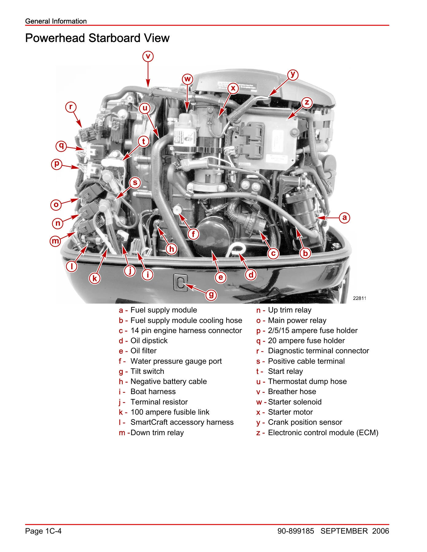
Powerhead Starboard Viewp. 44
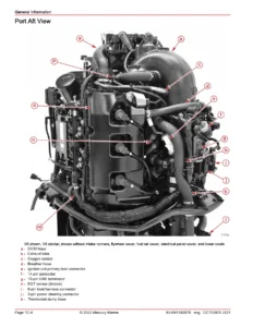
Powerhead Port Viewp. 45
Powerhead Aft Viewp. 46
Powerhead Top Viewp. 47
+Conditions Affecting Performancep. 48
Weatherp. 48
Weight Distribution (Passengers and Gear) Inside the Boatp. 48
Bottom of Boatp. 49
Water Absorptionp. 49
Cavitationp. 49
Ventilationp. 49
Detonationp. 49
+Following Complete Engine Submersionp. 50
Engine Submerged While Running (Special Instructions)p. 50
Fresh Water Submersion (Special Instructions)p. 50
Salt Water Submersion (Special Instructions)p. 51
+Fuel and Oilp. 51
+Fuel Recommendationsp. 51
Fuel Ratingsp. 51
Using Reformulated (Oxygenated) Gasolines (USA Only)p. 51
Gasolines Containing Alcoholp. 51
+Filling Fuel Tankp. 52
Portable Fuel Tank Placement in the Boatp. 52
Engine Oil Recommendationsp. 52
+Warning Systemp. 53
Warning Horn Signalsp. 53
Engine Guardian Systemp. 54
SmartCraft Productp. 54
+Power Trim and Tiltp. 54
Power Trim And Tiltp. 54
Power Trim Operationp. 55
Tilting Operationp. 56
Manual Tiltingp. 56
Auxiliary Tilt Switchp. 56
Shallow Water Operationp. 57
Compression Checkp. 57
+Cylinder Leakage Testingp. 58
+Painting Proceduresp. 58
Propellersp. 59
Gear Housingp. 59
Decal Removalp. 60
Decal Applicationp. 60
+1d.pdfp. 1
+Section 1D – Outboard Motor Installationp. 61
Table of Contentsp. 61
Important Informationp. 62
Boat Horsepower Capacityp. 62
Start in Gear Protectionp. 63
Selecting Accessories For Your Outboardp. 63
+Fuel Tanksp. 63
Portable Fuel Tankp. 63
Permanent Fuel Tankp. 63
Filling the Fuel Systemp. 63
Installation Specificationsp. 64
Lifting Outboardp. 64
Steering Cable – Starboard Side Routed Cablep. 65
Steering Link Rod Fastenersp. 65
Determining Recommended Outboard Mounting Heightp. 67
Drilling Outboard Mounting Holesp. 68
+Fastening the Outboard to the Transomp. 69
Mounting Boltsp. 69
Checking Boat Transom Constructionp. 69
+Electrical, Fuel Hose, and Control Cablesp. 71
+Front Cowl Grommetp. 71
Remote Wiring Harnessp. 72
SmartCraft Harness Connectionp. 72
+Battery Cable Connectionsp. 72
Single Outboardp. 72
Dual Outboardsp. 73
+Fuel Hose Connectionp. 73
Shift Cable Installationp. 73
Throttle Cable Installationp. 76
Trim In Pinp. 78
+2a.pdfp. 1
+Section 2A – Ignitionp. 79
Table of Contentsp. 79
Ignition Specificationsp. 80
Electrical Componentsp. 82
Electrical Plate Componentsp. 84
Cylinder Head and Camshaft Componentsp. 86
Integrated Air Fuel Module Componentsp. 90
Troubleshooting without a Computer Diagnostic System (CDS)p. 92
Troubleshooting with the Computer Diagnostic System (CDS)p. 92
Troubleshooting Guidep. 92
+Flywheelp. 95
Flywheel Removalp. 95
Flywheel Installationp. 97
+Electronic Control Module (ECM)p. 99
Electronic Control Module Removalp. 101
Electronic Control Module Installationp. 101
Wire Color Code Abbreviationsp. 102
+Main Power Relayp. 103
Main Power Relay (MPR)p. 103
Main Power Relay Testp. 103
+Ignition Pencil Coilp. 106
Ignition Coil Testp. 106
Ignition Coil Ohm Testp. 108
Ignition Coil Removalp. 109
Ignition Coil Installationp. 110
+Crankshaft Position Sensor (CPS)p. 111
Crankshaft Position Sensor Testp. 111
Crankshaft Position Sensor Removalp. 113
Crankshaft Position Sensor Installationp. 114
+Camshaft Position Sensorp. 114
Camshaft Position Sensor Testp. 115
Camshaft Position Sensor Removalp. 117
Camshaft Position Sensor Installationp. 118
+Throttle Position Sensor (TPS)p. 119
Throttle Position Sensor Testp. 119
+Cylinder Block Coolant Temperature Sensorp. 121
Cylinder Block Coolant Temperature Sensor Testp. 121
Cylinder Block Coolant Temperature Sensor Removalp. 123
Cylinder Block Coolant Temperature Sensor Installationp. 124
+Manifold Absolute Pressure (MAP) Sensorp. 125
Manifold Absolute Pressure Sensor Testp. 125
Manifold Absolute Pressure Sensor Removalp. 127
Manifold Absolute Pressure Sensor Installationp. 128
+Manifold Intake Air Temperature (MAT) Sensorp. 129
Manifold Intake Air Temperature Sensor Testp. 129
Manifold Intake Air Temperature Sensor Removalp. 131
Manifold Intake Air Temperature Sensor Installationp. 132
+Oil Pressure Sensorp. 133
Oil Pressure Sensor Testp. 133
Oil Pressure Sensor Removalp. 135
Oil Pressure Sensor Installationp. 136
+2b.pdfp. 1
+Section 2B – Charging and Starting Systemp. 137
Table of Contentsp. 137
Charging and Starting Specificationsp. 138
Alternator/Starboard Cylinder Block Componentsp. 140
Electrical Componentsp. 144
Electrical Plate Componentsp. 146
Starter Motorp. 148
+Batteryp. 150
Battery Cable Testp. 150
Original Battery Cable Length and Gauge Shipped With Enginep. 150
Battery Cable Size For Outboard Modelsp. 151
Replacement Partsp. 153
Recommended Batteryp. 153
Battery Precautionsp. 153
Charging a Discharged Batteryp. 154
Winter Storage of Batteriesp. 154
+Wire Harness Replacementp. 155
Wire Harness Removalp. 155
Wire Harness Installationp. 164
+Alternator Systemp. 175
+System Componentsp. 175
Alternator Descriptionp. 176
Diagnosis of Alternator System on the Enginep. 176
+Alternator System Circuitry Testp. 178
Output Circuitp. 178
Sensing Circuitp. 179
Excitation Circuitp. 179
Alternator Removalp. 180
Alternator Installationp. 182
+Starter Systemp. 184
Starter Motor Amperes Drawp. 184
Starting System Componentsp. 184
Starter System Descriptionp. 184
Starter Circuit Troubleshootingp. 184
+Starter Circuit Troubleshootingp. 185
Starter Circuit Troubleshooting Chartp. 186
Starter Removalp. 188
+Starter Solenoid Replacementp. 189
Starter Solenoid Installationp. 191
+Starter Motor Pinion Gear Replacementp. 194
Starter Motor Pinion Gear Installationp. 195
Starter Installationp. 196
Key Switch Test (4 Position)p. 198
+2c.pdfp. 1
+Section 2C – Timing, Synchronizing, and Adjustingp. 201
Table of Contentsp. 201
Ignition Specificationsp. 202
Idle Timing Adjustment (All Models)p. 202
Maximum Timing Adjustment (All Models)p. 202
Throttle Cable Adjustmentp. 203
+3a.pdfp. 1
+Section 3A – Theory of Operationp. 205
Table of Contentsp. 205
Air Induction Systemp. 206
Fuel Injection Systemp. 206
+Air Induction and Fuel Injection Systemp. 207
Fuel System Descriptionp. 207
Main Power Relay (MPR)p. 208
Intake Manifoldp. 208
Electronic Control Module (ECM)p. 208
Throttle Bodyp. 209
Idle Air Control (IAC)p. 210
Fuel Supply Module (FSM)p. 211
Vent Canister Switch (VCS)p. 211
Vent Canister Purge Valve (VCPV)p. 212
Fuel Float Switchp. 212
Fuel Lift Pumpp. 212
High Pressure Fuel Pumpp. 213
Fuel Pressure Regulatorp. 214
Fuel Coolerp. 214
Fuel Injectorp. 215
+3b.pdfp. 1
+Section 3B – Troubleshooting and Diagnosticsp. 217
Table of Contentsp. 217
Fuel System Specificationsp. 218
Troubleshooting With the Computer Diagnostic System (CDS)p. 220
Troubleshooting Without a Computer Diagnostic System (CDS)p. 220
Guardian Protection Systemp. 221
+Fuel System Component Troubleshooting and Diagnosticsp. 221
Anti-Siphon Valvesp. 221
Referencing Fuel Pressure Readingsp. 221
Fuel Pressure Calculations, Engine Runningp. 222
+Idle Air Control (IAC)p. 222
Idle Air Control (IAC) Testingp. 222
+Fuel Lift Pumpp. 223
Testing Fuel Lift Pump Vacuump. 224
High Pressure Fuel Pumpp. 225
Vent Canister Switch (VCS)p. 225
+Vent Canister Purge Valve (VCPV)p. 226
Vent Canister Purge Valve Testsp. 226
Fuel Supply Module (FSM)p. 229
+Fuel Injectorsp. 231
+3c.pdfp. 1
+Section 3C – Servicing Proceduresp. 235
Table of Contentsp. 235
Fuel System Specificationsp. 236
Fuel System Module Componentsp. 238
Integrated Air Fuel Modulep. 240
Integrated Air Fuel Module Componentsp. 242
Fuel System Module Mount Componentsp. 244
Fuel System Module Hosesp. 246
+Throttle Position Sensor (TPS) Removal and Installationp. 248
TPS Removalp. 248
TPS Installationp. 248
+Idle Air Control (IAC) Removal and Installationp. 249
IAC Removalp. 249
IAC Installationp. 249
+Vent Canister Purge Valve (VCPV) Removal and Installationp. 250
Vent Canister Purge Valve (VCPV) Removalp. 250
Vent Canister Purge Valve (VCPV) Installationp. 253
+Vent Canister Switch (VCS) Removal and Installationp. 254
Vent Canister Switch (VCS) Removalp. 254
Vent Canister Switch (VCS) Installationp. 255
+Fuel Railp. 256
Fuel Rail Removalp. 256
+Fuel Rail Disassembly and Reassemblyp. 259
Fuel Rail Disassemblyp. 259
Fuel Rail Reassemblyp. 260
Fuel Rail Installationp. 261
+Intake Manifoldp. 262
Intake Manifold Removalp. 262
Intake Manifold Disassemblyp. 268
Intake Manifold Reassemblyp. 271
Intake Manifold Installationp. 274
+Fuel System Module (FSM)p. 278
Fuel System Module Removalp. 278
+Fuel System Module Disassembly and Inspectionp. 282
FSM Disassemblyp. 282
FSM Inspectionp. 284
Fuel System Module Assemblyp. 285
Fuel System Module Installationp. 289
+3d.pdfp. 1
+Section 3D – Emissionsp. 293
Table of Contentsp. 293
+Exhaust Emission Standardsp. 294
What Are Emissions?p. 294
Hydrocarbons β HCp. 294
Carbon Monoxide β COp. 294
Oxides of Nitrogen – NOxp. 294
Controlling Emissionsp. 294
Stoichiometric (14.7:1) Air/Fuel Ratiop. 295
Outboard Hydrocarbon Emissions Reductionp. 295
+Emissions Informationp. 295
Manufacturers Responsibilityp. 295
Dealer Responsibilityp. 295
Owner Responsibilityp. 296
Exceptionsp. 296
EPA Emission Regulationsp. 296
Manufacturer's Certification Labelp. 296
+Service Replacement EPA Decalp. 297
Removalp. 297
Date Code Identificationp. 297
Installationp. 297
+4a.pdfp. 1
+Section 4A – Cylinder Block/Crankcasep. 299
Table of Contentsp. 299
Cylinder Block/Crankcase Specificationsp. 300
Cylinder Block Componentsp. 304
Crankshaft, Piston and Connecting Rod Componentsp. 306
Lower Cowl Removalp. 308
Powerhead Removalp. 310
+Removing Powerhead Componentsp. 314
Wire Harness Assembly Removalp. 314
Intake Manifold Assembly Removalp. 319
Throttle Bracket Removal and Disassemblyp. 321
FSM Assembly and Mounting Bracket Removalp. 322
Alternator Assembly and Mounting Bracket Removalp. 323
Starter Assembly Removalp. 324
Thermostat Housing Assembly Removalp. 325
Flywheel, Ground Strap, and Electrical Plate Grommet Removalp. 326
+Powerhead Disassemblyp. 328
Cylinder Head Removalp. 328
Crankcase and Crankshaft Disassembly/Removalp. 331
+Cleaning, Inspection and Repairp. 334
Measuring Cylinder Borep. 334
+Measuring Pistonp. 335
Piston Diameterp. 335
Piston Ring Groovep. 336
Piston Ring Side Clearancep. 336
Piston Ring End Gapp. 336
Piston Wrist Pin Diameterp. 337
Piston Wrist Pinp. 337
Measuring Connecting Rodp. 337
+Measuring Crankshaftp. 338
CRANKSHAFT RUN-OUTp. 338
CRANKSHAFT MAIN BEARING AND CRANK PIN MEASUREMENTp. 339
+Powerhead Reassemblyp. 339
Installing Oil Galley Plugsp. 339
Powerhead Pre-Assembly Cleaning Recommendationsp. 340
Selecting New Crankshaft Bearingsp. 341
Crankshaft Main Bearing Grade Selectionp. 341
Piston/Connecting Rod Assemblyp. 342
Connecting Rod Bearing Grade Selectionp. 342
Piston Ring Installationp. 344
Piston Assembly Installationp. 345
Installing the Timing Chain onto the Crankshaftp. 347
Cylinder Head Installationp. 349
Installing the Camshaft Gears and the Timing Chainp. 355
+Installing Upper Crankshaft Sealp. 358
New Crankshaft Installationp. 359
Original Crankshaft Installationp. 361
Installing the Lower Crankshaft Sealp. 362
+Installing Powerhead Componentsp. 363
Flywheel, Ground Strap, and Electrical Plate Grommet Installationp. 363
+Thermostat Removal and Installationp. 366
Thermostat Removalp. 366
Thermostat Testp. 366
Thermostat Installationp. 367
Thermostat Housing Assembly Installationp. 368
Starter Assembly Installationp. 371
Alternator Assembly and Mounting Bracket Installationp. 372
Fuel Supply Module (FSM) Assembly and Mounting Bracket Installationp. 374
Throttle Bracket Reassembly and Installationp. 375
Intake Manifold Assembly Installationp. 379
Wire Harness Installationp. 382
Powerhead Installationp. 389
Lower Cowl Installationp. 392
Engine Break-in Procedurep. 395
+4b.pdfp. 1
+Section 4B – Cylinder Headp. 397
Table of Contentsp. 397
Cylinder Head Specificationsp. 398
Cylinder Head and Camshaft Componentsp. 400
+Cylinder Head Disassemblyp. 404
Cam Removalp. 404
Valve Removalp. 404
Cylinder Head Galley Plug Removalp. 406
+Cleaning/Inspection/Repairp. 406
Camshaftp. 406
Valvesp. 407
Valve Springsp. 408
Cylinder Headp. 408
+Valve Guidesp. 409
VALVE GUIDE REPLACEMENTp. 409
Valve Seat Reconditioningp. 409
+Cylinder Head Reassemblyp. 412
Cylinder Head Galley Plug Installationp. 412
Valvesp. 412
Camsp. 414
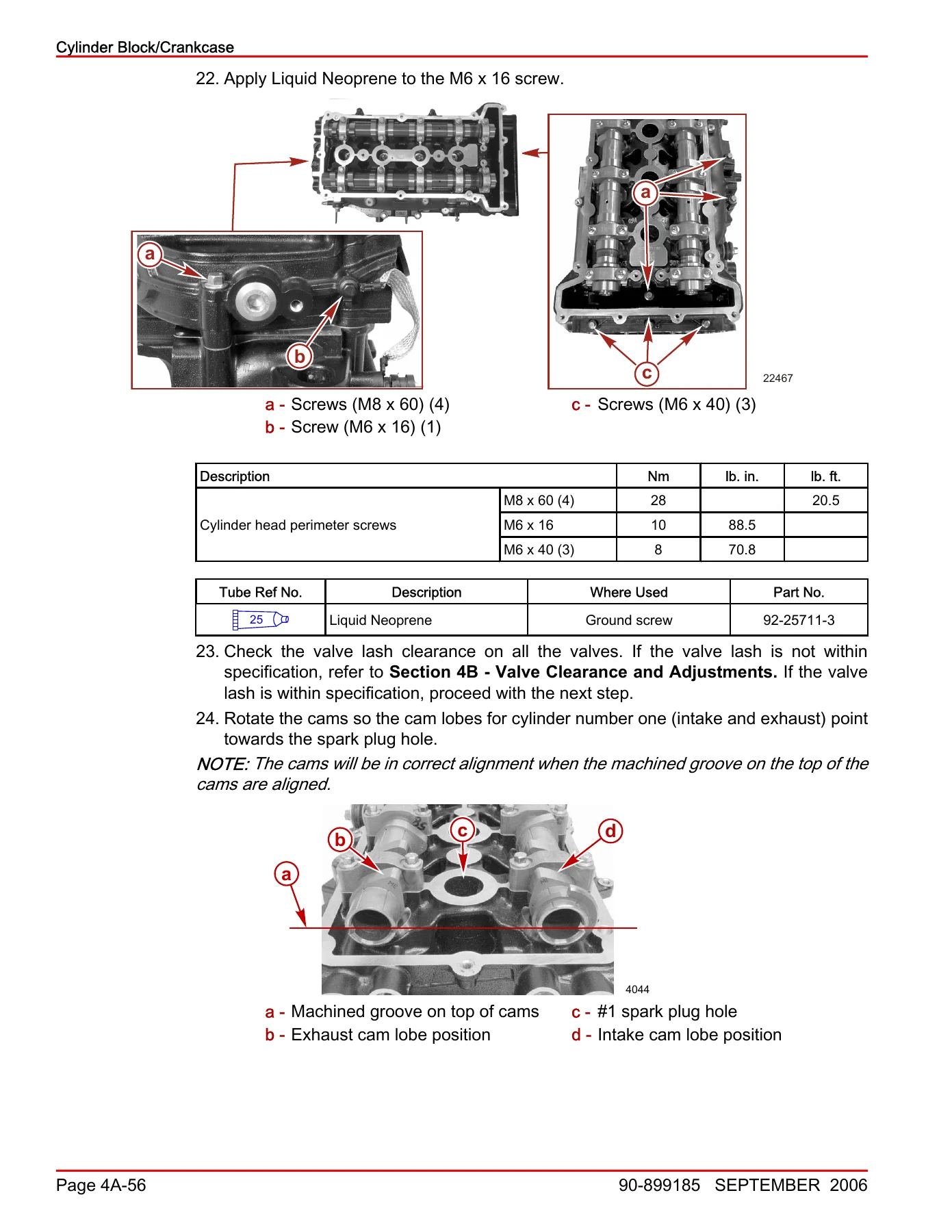
+Valve Clearance and Adjustmentsp. 415
Valve Clearance Measurement Stepsp. 415
Changing Valve Clearancep. 415
+4c.pdfp. 1
+Section 4C – Lubricationp. 419
Table of Contentsp. 419
Oil System Specificationsp. 420
Oil Pump Componentsp. 422
+Engine Guardian Systemp. 424
Low Oil Pressure, Engine Guardianp. 424
+Oil Pumpp. 424
Oil Pump Removalp. 424
Oil Pump Disassemblyp. 424
Oil Pump Reassemblyp. 428
+5a.pdfp. 1
+Section 5A – Clamp/Swivel Brackets and Driveshaft Housingp. 433
Table of Contentsp. 433
Mid-Section Specificationsp. 434
Swivel Bracket and Steering Arm Componentsp. 436
Transom Bracket Componentsp. 438
Adapter Plate Componentsp. 440
Oil Pump Componentsp. 444
Driveshaft Housing Componentsp. 446
Bottom Cowl Componentsp. 448
+Bottom Cowl Removal and Installationp. 450
Removalp. 450
Installationp. 450
+Lower Mountp. 452
Removalp. 452
Installationp. 453
Adapter Plate and Driveshaft Housing Removalp. 456
+Transom/Swivel Bracketp. 461
Disassemblyp. 461
Swivel Bracket/Pin Disassemblyp. 463
Swivel Bracket/Pin Assemblyp. 464
Transom/Swivel Bracket Assemblyp. 466
+Adapter Plate and Driveshaft Housing Reassemblyp. 468
Oil Sumpp. 468
Driveshaft Housing and Mountsp. 471
Oil Pumpp. 475
Shift Shaft Installationp. 476
+5b.pdfp. 1
+Section 5B – Power Trimp. 481
Table of Contentsp. 481
Power Trim Specificationsp. 482
Power Trim Componentsp. 484
+Power Trim General Informationp. 486
General Informationp. 486
Power Trim Operationp. 486
Trailering Boat/Outboardp. 487
Manual Tiltingp. 487
Wire Color Code Abbreviationsp. 488
+Power Trim Flow Diagramsp. 490
Trim Up Circuitp. 490
Tilt Circuitp. 492
Maximum Tiltp. 494
Trim Downp. 496
Shock Function Upp. 498
Shock Function Returnp. 500
Manual Tiltp. 502
Trim Limitp. 504
Reverse Operationp. 505
+Troubleshootingp. 505
+Hydraulic System Troubleshootingp. 506
Condition/Problemp. 506
Problem/Solutionp. 506
+Electrical System Troubleshootingp. 506
General Checksp. 506
Condition/Problemp. 507
Problem/Solutionp. 507
Power Trim Relay Test Procedurep. 507
Power Trim Electrical Circuitp. 509
Troubleshooting the Down Circuitp. 509
Troubleshooting the Up Circuitp. 510
Troubleshooting the Up and Down circuits (All Circuits Inoperative)p. 511
+Testing the Power Trim System with Test Gauge Kitp. 512
Up Pressure Checkp. 512
Down Pressure Checkp. 514
Power Trim System Removalp. 517
+Power Trim Disassemblyp. 519
Draining Power Trimp. 519
Trim Motor Removalp. 520
Power Trim Pump and Components Removalp. 521
Manifold Removalp. 522
Shock Rod Removalp. 523
Shock Rod Disassemblyp. 524
Memory Piston Removalp. 527
+Power Trim Cleaning, Inspection and Repairp. 528
Trim Motor Electrical Testsp. 528
+Power Trim Assemblyp. 530
+O-Ring and Seal Placementp. 530
Shock Rod Assemblyp. 533
Shock Rod Installationp. 535
Trim Limit Installationp. 536
Manual Release Valve Installationp. 537
Manifold Installationp. 538
+Power Trim Pump and Components Installationp. 539
Pump Installationp. 539
Pressure Operated Plugsp. 540
Trim Motor Installationp. 540
Bleeding Power Trim Unitp. 541
Power Trim System Installationp. 542
+6a.pdfp. 1
+Section 6A – Gear Housing – EZ Shiftp. 547
Table of Contentsp. 547
Gear Housing Specificationsp. 548
Gear Housing (Driveshaft) EZ Shift Componentsp. 554
Gear Housing (Propeller Shaft) EZ Shift Componentsp. 558
+General Service Recommendationsp. 560
Bearingsp. 560
Shimsp. 560
Sealsp. 561
Draining and Inspecting Gear Housing Lubricantp. 561
Gear Housing Removalp. 561
+Gear Housing Disassemblyp. 562
Water Pump Disassemblyp. 562
Shift Shaft Disassemblyp. 565
Bearing Carrier and Propeller Shaft Removalp. 566
Propeller Shaft Disassemblyp. 569
Propeller Shaft Inspectionp. 571
Pinion Gear, Driveshaft, and Forward Gear Removalp. 572
Upper Driveshaft Bearing Removalp. 574
Oil Sleeve Removalp. 575
Lower Driveshaft Bearing Race Removalp. 576
Forward Gear Bearing Race Removalp. 576
+Gear Housing Assemblyp. 577
Forward Gear Bearing Race Assemblyp. 577
Bearing Carrier Assemblyp. 577
Forward Gear Assemblyp. 583
Clutch Actuator Rod Assembly and Installationp. 584
Propeller Shaft Assemblyp. 585
Driveshaft Wear Sleeve Installationp. 587
Lower Driveshaft Bearing Race Installationp. 588
Oil Sleeve Installationp. 590
Driveshaft Upper Bearing Installationp. 590
Pinion Gear Depthp. 591
Forward Gear, Driveshaft Lower Bearing, Pinion Gear and Driveshaft Installationp. 595
Bearing Carrier and Propeller Shaft Installationp. 596
Forward Gear Backlashp. 598
Shift Shaft Assemblyp. 600
Water Pump Assembly and Installationp. 601
Gear Housing Pressure Testp. 606
Gearcase Installationp. 606
Filling Gear Housing with Lubricantp. 608
+Trim Tab Adjustment and Replacementp. 609
Replacementp. 609
Adjustmentp. 609
+7a.pdfp. 1
+Section 7A – Throttle/Shift Linkagep. 611
Table of Contentsp. 611
Throttle Bracket Assembly Componentsp. 614
Shift Assembly Componentsp. 616
+Throttle Lever Bracket Removal and Installationp. 618
Removalp. 618
Reassemblyp. 618
Installationp. 621
+Shift Bracket Removal and Installationp. 622
Removalp. 622
Installationp. 622
+7b.pdfp. 1
+Section 7B – Tiller Handlep. 625
Table of Contentsp. 625
Tiller Handle Assemblyp. 628
Steering Handle Componentsp. 630
Tiller Handle Bracket Componentsp. 632
+Tiller Handle Switch Replacementp. 636
Key Switch Removalp. 636
Key Switch Installationp. 636
Warning Horn Removalp. 637
Warning Horn Installationp. 637
Lanyard Stop Switch Removalp. 638
Lanyard Stop Switch Installationp. 638
Neutral Switch Removalp. 638
Neutral Switch Installationp. 640
Tiller Handle Wiring Diagramp. 641
Tiller Handle Removalp. 641
Tiller Handle Disassemblyp. 646
Tiller Handle Reassemblyp. 652
+Tiller Handle Installation Instructionsp. 659
Shift Link Rod Installation and Adjustmentp. 661
Co-pilot Installation and Friction Adjustmentp. 665
Wiring Harness Connectionp. 666
Tiller Handle Operationp. 667
+7c.pdfp. 1
+Section 7C – Hydraulic Steeringp. 669
Table of Contentsp. 669
Hydraulic Steering Specificationsp. 670
Hydraulic Steering Helm Fill Plug Configurationp. 670
Steering System Hydraulic Fittings Torque Specificationsp. 670
Steering Cylinder Componentsp. 672
+Hydraulic Steering Systemsp. 674
Single Helm – Single Cylinderp. 674
Dual Helm – Single Cylinderp. 675
Single Helm – Dual Cylinderp. 676
Dual Helm – Dual Cylinderp. 677
+Steering Cylinderp. 678
Hydraulic Steering Systemp. 678
Connection of the Hydraulic Hoses to the Steering Helmp. 678
Connection of the Hydraulic Hoses to the Steering Cylinderp. 679
Power Filling and Purging the Hydraulic Steering Systemp. 679
+Manually Filling and Purging the Hydraulic Type Steering Systemp. 679
Step 1p. 680
Step 2p. 680
Step 3p. 681
Steering Cylinder Removalp. 682
Steering Cylinder Installationp. 683
+notice.pdfp. 1
Notice to Users of This Manualp. 2
Precautionsp. 3
Replacement Partsp. 3
Cleanliness and Care of Productp. 3
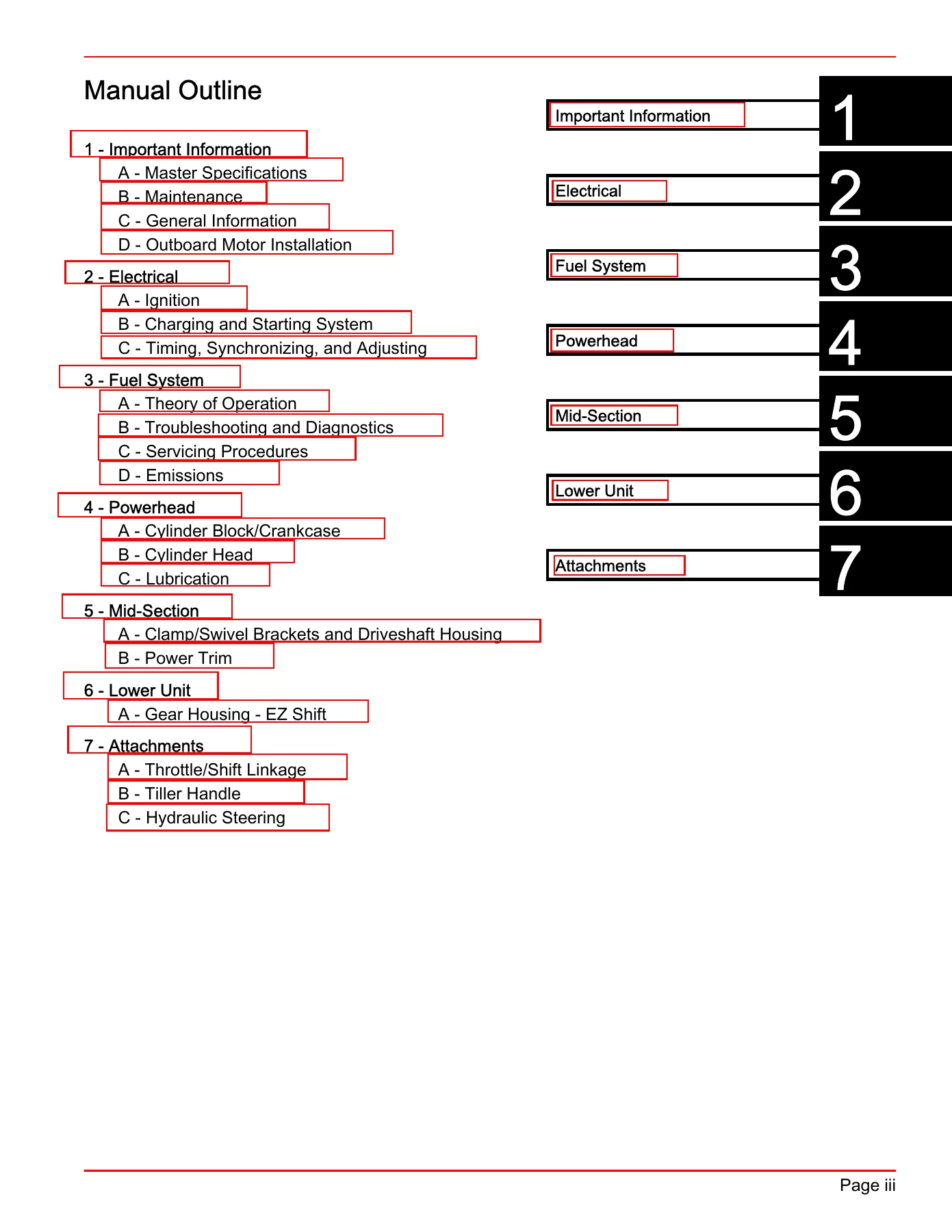
Manual Outlinep. 1
What Each Section Covers
Important Information section opens with the master specification tables and the owner maintenance schedule – before each use, after each use, every 100 hours or yearly, every 300 hours or three years, and before storage. It also covers corrosion control anodes, battery inspection, alternator belt inspection, cooling system flushing, cowl and flywheel cover removal, air filter service, fuel line inspection, low-pressure and high-pressure fuel filter service, power trim fluid checks, engine oil and filter changes, spark plug service, fuse replacement, propeller replacement, lubrication points, gearcase lubrication, and storage preparation.
Electrical section covers the digital inductive ignition system, spark plug specifications and torque, the flywheel, the Electronic Control Module (ECM), the main power relay, ignition pencil coils, crankshaft position sensor, camshaft position sensor, throttle position sensor, cylinder block coolant temperature sensor, manifold absolute pressure sensor, manifold intake air temperature sensor, and oil pressure sensor – each with test procedures, ohm values, removal, and installation. The charging and starting section covers the 50-amp regulated alternator, battery cable sizing charts, starter system, starter solenoid, neutral start circuit, and the 4-position key switch test. Timing is not adjustable; the ECM controls idle and wide-open-throttle timing, and the throttle cable adjustment procedure is given in full.
Fuel System section explains the air induction and sequential multi-port fuel injection design in detail, then provides troubleshooting with and without the CDS, fuel pressure calculations, fuel system component diagnostics (anti-siphon valves, idle air control, fuel lift pump, high-pressure fuel pump, vent canister switch, vent canister purge valve, fuel supply module, and fuel injectors), and full servicing procedures for the TPS, IAC, VCPV, VCS, fuel rail, intake manifold, and Fuel Supply Module (FSM). The Emissions section covers hydrocarbon, CO, and NOx standards and the EPA certification label.
Powerhead section is the largest, covering the 1.7L cylinder block and crankcase, crankshaft, pistons, connecting rods, cylinder head, camshafts, valves, valve lash adjustment, and the oil pump. It includes the full teardown and reassembly sequence with bearing grade selection charts, piston ring end-gap specifications, crankshaft run-out limits, and cam gear timing procedure.
Mid-Section section covers swivel bracket, steering arm, transom bracket, adapter plate, driveshaft housing, lower mounts, and the complete power trim system – including hydraulic flow diagrams for trim up, tilt, trim down, shock function, manual tilt, trim limit, and reverse operation, plus troubleshooting, test gauge procedures, disassembly, and assembly.
Lower Unit section covers the EZ Shift gear housing: gear ratios (2.33:1 for 75/90 and EU 80/100, 2.07:1 for the 115), forward gear and pinion tooth counts, pinion height, forward gear backlash, water pressure specs, leak test values, water pump, shift shaft, bearing carrier, propeller shaft, pinion gear depth, and pressure testing.
Attachments section covers the throttle and shift linkage bracket, the tiller handle (including key switch, warning horn, lanyard stop switch, neutral switch, and co-pilot friction adjustment), and the hydraulic steering system with single/dual helm and single/dual cylinder configurations, filling and purging procedures, and steering cylinder service.
Specifications You Will Find Inside
- 1.7L (105.6 cu in.) displacement, 10:1 compression ratio, 82.0 mm bore and stroke
- Full throttle RPM: 5000-6000 (75/90, EU 80/100) and 5800-6400 (115)
- Idle RPM: 700 Β± 50 (all models), firing order 1-3-4-2
- Spark plug NGK LFR4A-E, gap 0.8 mm (0.032 in.), torque 27 Nm (20 lb. ft.)
- Alternator output: 24 A at 1000 RPM, 40 A at 3000 RPM (battery)
- Starter draw: 200 A under load, 65 A no load
- Engine oil capacity: 5.0 liters (5.2 qt.) with filter
- Gearcase capacity: 710 ml (24 fl. oz.) High Performance Gear Lubricant
- Fuel: automotive unleaded, minimum 87 octane (90 RON)
- Trim/tilt: maximum tilt range 73Β°, maximum trim range 20Β°
Who This Mercury 75-115 EFI FourStroke Manual Is For
This 2006 Mercury outboard service manual is written for the technician, dealer service department, or experienced owner who needs the manufacturer’s own procedures and specifications rather than guesswork. Because the same 1.7L EFI FourStroke platform spans five horsepower ratings in this manual, it covers the shared mechanical and electrical systems across the 75, 80, 90, 100, and 115 models, while calling out the differences in gear ratio, RPM range, camshaft profile, and propeller recommendations where they apply.
If you are working on a 2006 or newer Mercury 75 EFI FourStroke, 90 EFI FourStroke, 115 EFI FourStroke, or the EU-market 80 and 100 versions, this manual gives you the torque specifications, clearances, diagnostic paths, and assembly sequences to do the job correctly. Correct torque on the long main bolts, the right crankshaft bearing grade, the correct forward gear backlash, and the proper fuel pressure calculation all matter – get any of them wrong and you risk premature failure of a rebuild.
Get the Mercury 90-899185 Service Manual Instantly
This Mercury 75-115 EFI FourStroke outboard service manual (90-899185, September 2006) is delivered as an instant PDF download – no shipping, no waiting. Open it on a laptop in the shop, a tablet at the dock, or a phone on the water, and print only the pages you need for the job in front of you. With 686 pages covering every major system on the 1.7L EFI FourStroke, from routine oil changes and spark plug service to powerhead disassembly and gearcase rebuilds, this is the reference you will keep coming back to for the life of the engine.
Reviews
There are no reviews yet.