Description
Mercury FourStroke CMS Outboard Service Manual β V6 175-225hp & V8 200-300hp
This is the full service manual for the Mercury Marine V6 175-225hp and V8 200-300hp FourStroke outboards built on the Conventional Midsection (CMS) platform. It is the document a technician reaches for when a job moves past routine maintenance β diagnosing an electrical fault, tearing down a powerhead, shimming a gear housing, or setting pinion height to spec. Every procedure is written against the factory design, so the torque values, tolerances, and sequences match what the engine was assembled with. The manual covers V6 models from 175hp through 225hp and V8 models from 200hp through 300hp, including Pro XS and SeaPro variants where the underlying hardware differs.
File Details
- Manual type: Service / repair manual
- Brand: Mercury Marine
- Models covered: V6 175-225hp, V8 200-300hp FourStroke CMS outboards
- Document number: 90-8M0182078
- Publication date: October 2021
- Language: English
- Page count: 976 pages
- File format: PDF (instant download)
Chapters Covered
The manual is organized into eight numbered sections, each broken into lettered sub-sections. The top-level structure follows the engine, system by system.
- 1 β Important Information
- A β Master Specifications
- B β Maintenance
- C β General Information
- D β Outboard Installation
- E β Storage
- F β General Troubleshooting
- 2 β Electrical
- A β Ignition
- B β Charging and Starting System
- C β Accessories
- D β Throttle and Shift
- 3 β Fuel System
- A β Induction System
- B β Service Procedures
- C β Emissions
- D β Fuel Flow Diagrams
- 4 β Powerhead
- A β Cylinder Block/Crankcase
- B β Cylinder Head V6
- C β Cylinder Head V8
- D β Lubrication
- E β Cooling
- 5 β Midsection
- A β Clamp/Swivel Brackets and Driveshaft Housing
- B β Conventional Midsection (CMS) Power Trim
- C β Upper and Lower Cowls
- 6 β Gear Housing
- A β Right-Hand and Left-Hand Rotation (4.8 in. diameter)
- B β Right-Hand and Left-Hand Rotation (5.44 in. diameter)
- C β Torque Master
- 7 β Steering
- A β Power Steering
- B β Hydraulic Steering
- C β CMS Tie Bar Kits
- D β Power Steering Wiring Diagrams
- E β Tiller Handle
- 8 β Color Diagrams
- A β Color Diagrams (oil flow and cooling flow)
What This Manual Actually Gives You
The value of this manual is not just in the page count β it is in how tightly the content is written around this specific engine family. The Master Specifications section alone lists the numbers a technician needs before touching a fastener: compression ratio, bore and stroke, valve lash, oil pressure at idle and WOT, fuel pressure at key-up and idle, thermostat opening temperatures, spark plug gap and torque, and gear housing backlash tolerances for each of the three gearcase variants. Instead of guessing at a general value, you can look up the exact figure for a V8 250 Pro XS or a V6 200 SeaPro and work to it.
Section 2 (Electrical) goes beyond simple wiring. It covers the SmartCraft PCM 112 ignition system, crankshaft and camshaft position sensors, the MAP and MAT sensors, the wideband oxygen sensor, and the full charging and starting circuit β including the 85A and 115A alternator variants, belt replacement with the flywheel socket and alternator belt shoe, and starter solenoid disassembly. The ignition coil removal and installation procedures are written so the coils can be removed without pulling the intake runners, which matters when you are chasing a misfire on a hot engine.
Section 3 (Fuel System) documents the entire fuel supply module (FSM), not just the external filter. You get disassembly and assembly of the FSM itself β the lift pump, high-pressure pump, regulator, manifold, and seal grommets β along with the correct priming procedures for both the purge-tool method and the cranking method used after a run-dry condition. The fuel rail removal and installation procedures for V6 and V8 cover injector O-rings, Schrader valve orientation, and the injector clip locking sequence. The section also includes fuel flow diagrams and the EPA emissions information needed for certification work.
Section 4 (Powerhead) is the largest part of the manual. It covers cylinder block and crankcase disassembly, measuring cylinder bore for taper and out-of-round, piston and ring inspection, connecting rod measurement, and crankshaft runout and journal identification. The bearing selection charts let you match crankshaft journal codes and cylinder block codes to the correct bearing color β green, blue, white, or orange β without guesswork. Cylinder head sections for V6 and V8 include valve removal, valve guide measurement, seat reconditioning angles, valve spring testing, and the Lash for Life adjustment procedure for setting valve clearance with bucket tappets. Lubrication and cooling sections cover the oil pump, oil pressure and temperature sensors, thermostat assembly, block water pressure sensor, and exhaust gas temperature sensor.
Section 5 (Midsection) covers the transom and swivel brackets, the driveshaft housing, the adapter plate, the exhaust tube, and the CMS power trim unit. The power trim section is detailed enough to take the pump and motor apart: it includes trim cylinder removal, tilt ram disassembly, memory piston removal, pump and component assembly, and the priming procedure. Troubleshooting charts for the power trim system walk through symptoms β trim motor runs but no movement, outboard trims opposite the button, system leaks down β and point to the specific valve or seal to inspect.
Section 6 (Gear Housing) is divided by gearcase size and rotation. The 4.8 in. diameter, 5.44 in. diameter, and Torque Master gearcases each get their own specifications, bearing carrier procedures, driveshaft removal and inspection, pinion bearing removal and installation, pinion height adjustment, front and rear gear backlash measurement, and propeller shaft bearing preload. The manual shows both the pinion gear locating tool method and the older locating tool method, and gives the exact shim-change math β for example, adding 0.025 mm of shim changes backlash by approximately 0.025 mm β so you can dial in the gear pattern instead of swapping parts.
Section 7 (Steering) covers power steering and hydraulic steering, including the steering cylinder, tie bar kits, and the DTS tiller handle. The power steering section includes wiring diagrams for single and dual engine battery architectures, the automatic power switch (APS) requirement for multi-engine installations, and the filling and purging procedure using the power steering module primer kit. The tiller handle section covers mounting, harness connections, throttle and shift cable installation, lever adaptation with CDS G3, and the trailering clip setup.
Section 8 provides full-color oil flow and cooling flow diagrams for both V6 and V8, including the Pro XS serial-number break at 3B050618. These are the diagrams you want when tracing a cooling restriction or verifying that oil is reaching the camshaft feeds and timing chain tensioner.
Who This Manual Is For
This is a dealer-level service manual written for mechanics who already understand marine outboard service procedures and are trained on Mercury power products. It assumes familiarity with hand tools, torque wrenches, and special tools like the flywheel socket, alternator belt shoe, bearing carrier retainer nut wrench, and pinion gear locating tools. That said, the procedures are written step by step with callouts, so a competent DIY owner who is willing to buy or borrow the special tools can follow them β especially for jobs like water pump replacement, gearcase removal, thermostat replacement, or power trim service. For anything involving the PCM, DTS calibration, or valve lash adjustment, the manual is explicit that factory procedures and CDS G3 diagnostics are required.
Why the Correct Numbers Matter
Outboard engines are built to tight tolerances, and this manual is the only reliable way to know what those tolerances are for this platform. A gearcase assembled with the wrong pinion height will whine and fail early. A powerhead torqued without the correct bedplate bolt sequence and angle steps can distort the main bearing bore. A fuel system primed without purging the FSM can damage the fuel pumps. The torque tables, shim charts, and step-by-step sequences in this manual exist specifically to prevent those failures. Working without them means guessing, and guessing on a 300hp V8 is expensive.
Complete PDF Bookmark Tree
Complete Bookmarks
The complete bookmarks in the βMercury Marine V6 175-225hp & V8 200-300hp FourStroke CMS Outboard Service Manualβ are as follows:
Notice to Users of This Manualp. 3
Precautionsp. 3
Replacement Partsp. 3
Cleanliness and Care of Productp. 4
Copyright and Trademark Informationp. 4
Manual Outlinep. 5
+1A Important Information – Master Specificationsp. 7
V8 CMS General Specificationsp. 8
V6 CMS General Specificationsp. 9
Ignition Specifications – V8 Modelsp. 10
Ignition Specifications – V6 Modelsp. 11
PCM Overspeed Limiter Specificationsp. 11
Charging and Starting Specificationsp. 12
Battery Specificationsp. 12
Fuel System Specificationsp. 12
V8 Cylinder Block/Crankcase Specificationsp. 13
V6 Cylinder Block/Crankcase Specificationsp. 14
V8 Cylinder Head Specificationsp. 14
V6 Cylinder Head Specificationsp. 15
Lubrication System Specificationsp. 17
Cooling System Specificationsp. 17
Conventional Midsection (CMS) Power Trim Specificationsp. 17
Swivel Bracket and Driveshaft Housing SpecificationsβCMSp. 17
+Gear Housing Specificationsp. 18
Gear Housing Specifications (4.8 in. Diameter)p. 18
Gear Housing Specifications (5.44 in. Diameter)p. 18
Gear Housing Specifications (Torque Master)p. 19
+Steering System Specificationsp. 19
Power Steering Specificationsp. 19
Hydraulic Steering Specificationsp. 19
+1B Important Information – Maintenancep. 21
+Cleaning Care Recommendationsp. 23
Do Not Use Caustic Cleaning Chemicalsp. 23
Cleaning Gaugesp. 23
Cleaning Remote Controlsp. 23
+Cleaning Care for Top and Bottom Cowlsp. 23
Cleaning and Waxing Procedurep. 23
Cleaning Care for the Powerhead (Saltwater Use)p. 23
+EPA Emissions Regulationsp. 24
Emission Certification Labelp. 24
Owner Responsibilityp. 24
+Inspection and Maintenance Schedulep. 24
Before Each Usep. 24
After Each Usep. 24
Every 100 Hours of Use or Once Yearly, Whichever Occurs Firstp. 25
Every 300 Hours of Use or Three Yearsp. 25
Before Periods of Storagep. 25
+Maintenance Schedule Decalsp. 26
Maintenance Schedule Decal Iconsp. 26
V6 FourStroke Models Maintenance Schedule Decalp. 26
V6 Pro XS Models Maintenance Schedule Decalp. 27
SeaPro V6 Models Maintenance Schedule Decalp. 27
V8 FourStroke Models Maintenance Schedule Decalp. 28
V8 Pro XS Models Maintenance Schedule Decalp. 28
SeaPro V8 Models Maintenance Schedule Decalp. 29
Flushing the Cooling Systemp. 29
+Top Cowl Removal and Installationp. 29
Removalp. 29
Installationp. 30
Battery Inspectionp. 31
+Battery Cables and Clean Power Harnessp. 31
Battery Connectionsp. 31
Order of Connectionp. 32
+Fuel Systemp. 32
Fuel Line Inspectionp. 32
+Low-Pressure Fuel Filterp. 32
Removalp. 32
Installationp. 33
Corrosion Control Anodep. 34
+Propeller Replacementp. 34
Flo-Torq II Propellersβ25.4 mm (1 in.) Propeller Shaftp. 35
Flo-Torq IV Propellersβ25.4 mm (1 in.) Propeller Shaftp. 35
Propeller Replacementβ31.75 mm (1-1/4 in.) Diameter Propeller Shaftp. 36
Spark Plug Inspection and Replacementp. 37
Fusesp. 38
Alternator Drive Beltp. 39
Lubrication Pointsp. 39
Checking Power Trim Fluidp. 41
Checking Hydraulic Steering Fluidp. 41
Checking Power Steering Fluidp. 41
+Changing Engine Oil and Filterp. 42
Engine Oil Capacityp. 42
Oil Change On Land Procedurep. 42
Oil Change On Water Procedurep. 43
Changing Oil Filterp. 44
Oil Fillingp. 44
+Checking Engine Oil Levelp. 44
Dipstick Bead Oil Level Overviewp. 45
Exhaust Water Strainer Inspectionp. 45
+Gearcase Lubricantp. 47
Gearcase Lubricationp. 47
Recommended Gearcase Lubricationp. 48
Gearcase Lubricant Capacityp. 48
+Draining and Filling the Gearcase – 122 mm (4.8 in.)p. 48
Draining Gearcasep. 48
Filling the Gearcasep. 48
Checking Lubricant Levelp. 48
+Draining and Filling the Gearcase – 137 mm (5.4 in.)p. 49
Draining Gearcasep. 49
Filling the Gearcasep. 49
Checking Lubricant Levelp. 49
+Draining and Filling the Gearcase SeaPro Modelsp. 50
Filling the Gearcasep. 50
Checking Lubricant Levelp. 50
+1C Important Information – General Informationp. 51
Recording Serial Numberp. 52
Selecting Accessories for Your Outboardp. 52
Front Viewp. 53
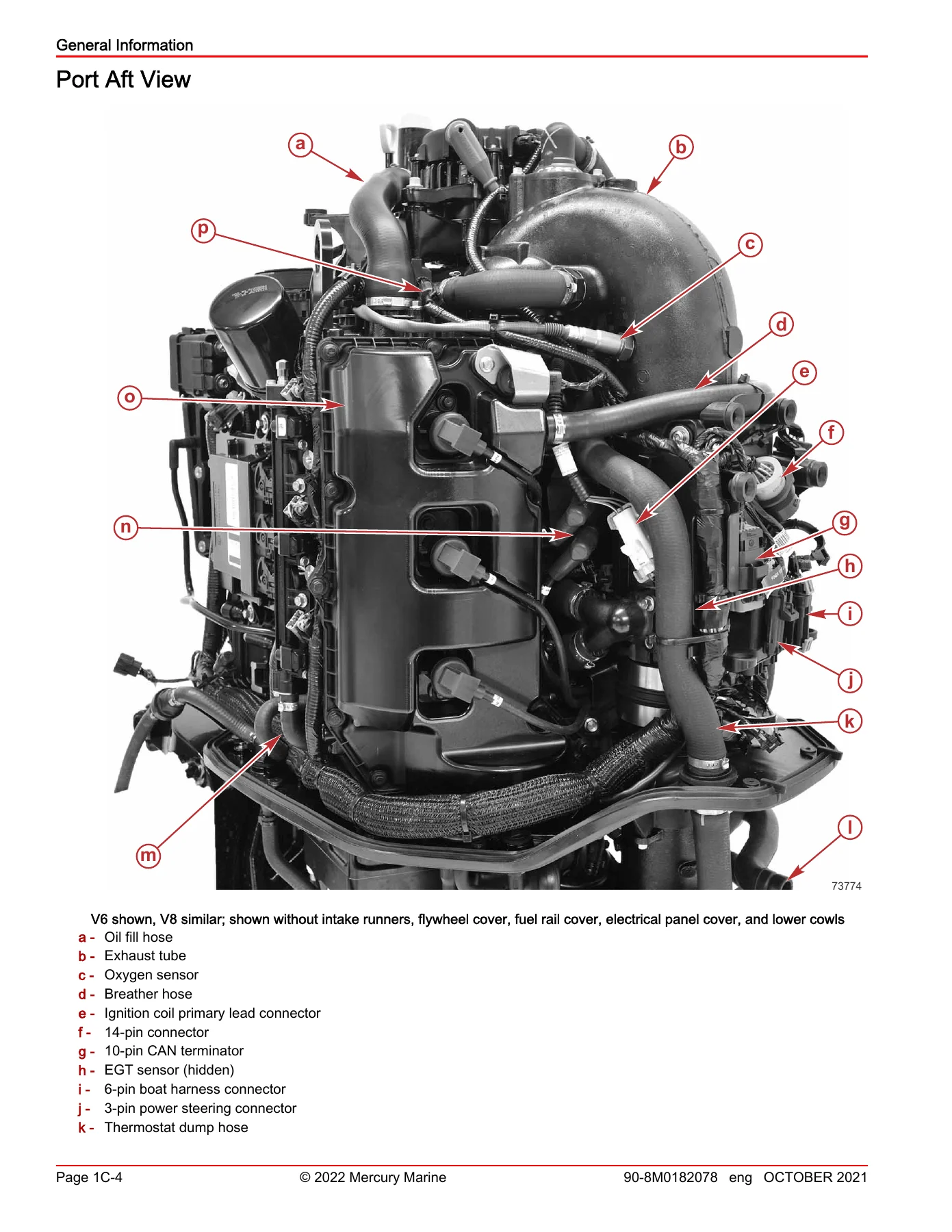
Port Aft Viewp. 54
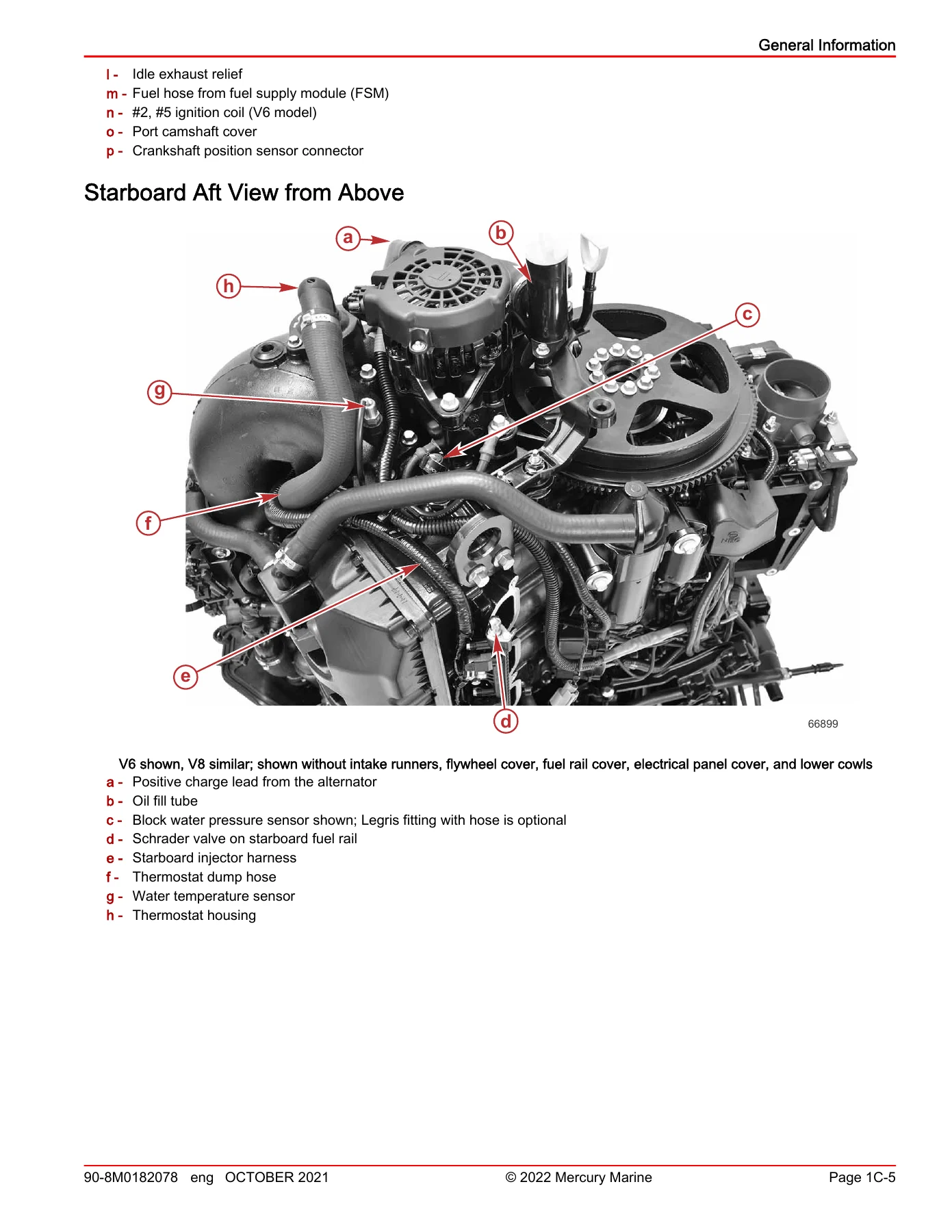
Starboard Aft View from Abovep. 55
Aft Viewp. 56
Starboard Aft Viewp. 57
Port Viewp. 58
Starboard Viewp. 59
+Conditions Affecting Performancep. 60
Weatherp. 60
Weight Distribution (Passengers and Gear) Inside the Boatp. 60
Bottom of Boatp. 60
Water Absorptionp. 60
Cavitationp. 61
Ventilationp. 61
Detonationp. 61
+Following Complete Engine Submersionp. 61
Engine Submerged While Running (Special Instructions)p. 61
Freshwater Submersion (Special Instructions)p. 61
Saltwater Submersion (Special Instructions)p. 62
+Power Trim and Tiltp. 62
Power Trim Operationp. 62
Tilting Operationp. 63
Manual Tiltingp. 63
Auxiliary Tilt Switchp. 64
Operating in Shallow Waterp. 64
+Cylinder Leakage Testingp. 64
+Paint Codes and Painting Proceduresp. 65
Painting ProceduresβPropellersp. 65
+Paint Codesp. 65
Verado Silver Paint Code (Torque Master II)p. 65
Painting Procedure Using Verado Silver Paint Codep. 65
Gearcase and Lower Housing Refinishingp. 67
Cowl Refinishingp. 67
Decal Removalp. 68
Raised Decal Removalp. 68
+1D Important Information – Outboard Installationp. 71
+Important Informationp. 72
+Steering System Requirementsp. 72
Mechanical Steeringp. 72
Hydraulic Steering (Non-Power Steering)p. 72
Hydraulic Power Steeringp. 72
+Multiple Engine Steering Installationsp. 73
+Dual Outboard Steering Optionsp. 73
Maximum Combined 500 hpp. 73
Maximum Combined 600 hpp. 73
Triple Outboard Steeringp. 73
Notice to Installer – DTS Modelsp. 73
Mercury Marine Validated Engine Mounting Hardwarep. 73
Fastening Hardware Specification (Not Factory Supplied)p. 73
+Accessories Mounted to the Transom Clamp Bracketp. 74
Acceptable Accessory Mounting to the Transom Clamp Bracketp. 74
Unacceptable Accessory Mountingp. 75
+Exceptions to the Accessory Mountingp. 76
Figure 2p. 77
Figure 3p. 77
Avoiding Loss of Throttle and Shift Control (DTS Engines)p. 77
Boat Horsepower Capacityp. 77
+Battery Requirementsp. 78
+Battery Cablesp. 78
Battery Cable Sizingp. 78
Cranking Circuit Cablesp. 78
Clean Power Connectionsp. 79
Battery Cable Connectionsp. 79
Battery Switchesp. 79
+Battery Isolationp. 81
Control, Isolation, and Charging Componentsp. 81
Isolation Cable Sizingp. 81
Auxiliary Loads and Power Sourcep. 81
Isolated Battery Architecturep. 81
Engine Battery Specificationsp. 82
+Installing the Outboardp. 83
Installation Specificationsp. 83
Determining Recommended Outboard Mounting Heightp. 84
Maximum Outboard Mounting Heightp. 84
+Before You Drillp. 85
Required Mounting Installation (175β300)p. 85
Alternate Mounting Installation (300 or 300R)p. 85
Drilling Outboard Mounting Holesp. 86
Lifting the Outboardp. 86
Transom Mounting Hardwarep. 87
+Fastening the Outboard to the Transomp. 87
Steering Cylinder Special Noticep. 88
Installationp. 88
Checking Boat Transom Constructionp. 89
Shipping Bracket Removalp. 90
+Wiring Guidelinesp. 90
DTS Special Notices and Guidelinesp. 90
+Harness and Connector Guidelinesp. 91
Harness Installation Guidelinesp. 91
Connectorsp. 91
Data Harness Pulling Procedurep. 91
System Wiring Reference Pointsp. 91
Wiring Accessoriesp. 92
+Rigging the Enginep. 92
Rigging Tube and Rigging Adapterp. 92
Connections at the Enginep. 92
Connections at the Remote Control (Mechanical Engines)p. 96
+Water Tubing Connectionsp. 96
Speedometer Tubing Connection (All Models)p. 96
Block Water Pressure Tubing Connection (Mechanical Models)p. 96
Connections at Rigging Tubep. 97
Throttle Cable Installationp. 97
Shift Cable Installationp. 98
Rigging Access Panelp. 99
Rigging Grommetp. 100
Installing the Steering Systemp. 102
+Battery Connectionsp. 102
Order of Connectionp. 102
Connecting Battery Cables and Clean Power Harnessp. 102
+Fuel Systemp. 103
Accessory Electric Fuel Pumpp. 103
Avoiding Fuel Flow Restrictionp. 103
Low Permeation Fuel Hose Requirementp. 104
Fuel Demand Valvep. 104
+Fuel Supply Module Priming Procedurep. 104
Priming the FSM with a Purge Toolp. 104
Priming the FSM (Ran out of Fuel Condition)p. 105
Adaptive Speed Control (ASC) Propping with CDS G3p. 105
Adaptive Speed Control (ASC) Propping without CDS G3p. 106
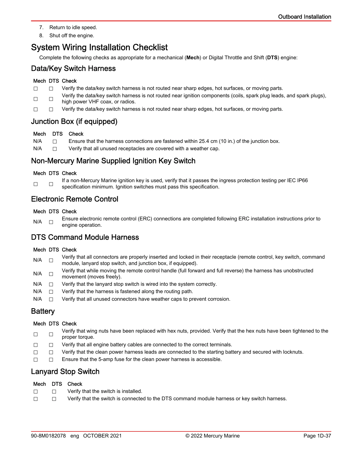
+System Wiring Installation Checklistp. 107
Data/Key Switch Harnessp. 107
Junction Box (if equipped)p. 107
Non-Mercury Marine Supplied Ignition Key Switchp. 107
Electronic Remote Controlp. 107
DTS Command Module Harnessp. 107
Batteryp. 107
Lanyard Stop Switchp. 107
+1E Important Information – Storagep. 109
+Storage Preparationp. 110
Protecting External Outboard Componentsp. 110
Protecting Internal Engine Componentsp. 110
Gearcasep. 111
Positioning Outboard for Storagep. 111
Battery Storagep. 111
+1F Important Information – General Troubleshootingp. 113
Troubleshooting without the Computer Diagnostic System (CDS G3)p. 114
+Troubleshooting with the Computer Diagnostic System (CDS G3)p. 114
About CDS G3p. 114
Additional Informationp. 114
Troubleshooting Guidep. 114
+Audio Warning Systemp. 117
Cautionp. 118
Criticalp. 118
Nonconfigured Alarmp. 118
Testing the Audio Warning Systemp. 118
+2A Electrical – Ignitionp. 119
Electrical Component Replacement Proceduresp. 120
Engine Harness and Sensors – V8p. 122
Engine Harness and Sensors – V6p. 124
Ignition Components – V8p. 126
Ignition Components – V6p. 128
+Flywheelp. 130
Flywheel Identificationp. 130
Flywheel Removalp. 131
Flywheel Installationp. 132
+Propulsion Control Module (PCM)p. 132
PCM Removalp. 133
PCM Installationp. 133
+Ignition Coil Removal and Installationp. 133
Removalp. 134
Installationp. 134
Main Power Relay (MPR)p. 135
+Sensor Replacement Proceduresp. 135
+Camshaft Position Sensorp. 135
Camshaft Position Sensor Removalp. 135
Camshaft Position Sensor Installationp. 135
+Crankshaft Position Sensor (CPS)p. 135
Crankshaft Position Sensor Removalp. 136
Crankshaft Position Sensor Installationp. 136
+Manifold Absolute Pressure (MAP) Sensorp. 136
Manifold Absolute Pressure (MAP) Sensor Removalp. 136
Manifold Absolute Pressure (MAP) Sensor Installationp. 137
+Manifold Air Temperature (MAT) Sensorp. 137
Manifold Air Temperature (MAT) Sensor Removalp. 137
Manifold Air Temperature (MAT) Sensor Installationp. 137
+Oxygen (O2) Sensorp. 138
Sensor Removalp. 138
Sensor Installationp. 138
Fusesp. 138
+2B Electrical – Charging and Starting Systemp. 141
Battery Specificationsp. 142
Alternator, Belt, and Mounting Components – V8p. 144
Alternator, Belt, and Mounting Components – V8 SN 3B056353 and Abovep. 146
Alternator, Belt, and Mounting Components – V6p. 148
Starter Motor and Hot Stud Componentsp. 150
+Batteryp. 152
Replacement Partsp. 152
Battery Precautionsp. 152
Charging a Discharged Batteryp. 152
+Charging Systemp. 153
Charging System Precautionsp. 153
Charging System Inspectionp. 153
Alternator Identificationp. 154
Alternator Removalp. 154
Alternator Installationp. 157
+Starting Systemp. 160
Starting System Visual Checksp. 160
Starter Removalp. 160
Starter Solenoid Removalp. 161
Starter Solenoid Installationp. 162
Starter Installationp. 164
Start Relayp. 165
+2C Electrical – Accessoriesp. 167
Analog Block Water Pressure Adapter Installationp. 168
Analog Gauges (DTS Models)p. 169
+Moving Propeller (MP) Alertp. 170
Note on Removalp. 170
Installationp. 170
Bezelp. 172
Operational Checkp. 172
+Oil Level Sensorp. 172
Oil Level Sensor Removalp. 172
Oil Level Sensor Installationp. 173
+Open Rigging Grommet (Optional Accessory)p. 173
Mechanical Rigging Grommet Installationp. 173
DTS Rigging Grommet Installationp. 175
+Pitot Pressure Sensor Removal and Installationp. 176
Removalp. 176
Installationp. 176
Repower Extension Harnessesp. 177
+2D Electrical – Throttle and Shiftp. 179
Mechanical Throttle and Shift Componentsp. 182
Shift Actuator Componentsp. 184
+Throttle and Shift Bracketp. 186
+Throttle Armp. 186
Removalp. 187
Installationp. 187
Shift Armp. 188
+Demand Sensorsp. 188
Sensor Removalp. 188
Sensor Installationp. 189
+Shift Actuatorp. 189
Shift Actuator Removalp. 189
Shift Actuator Installationp. 190
+3A Fuel System – Induction Systemp. 193
+Exploded Viewsp. 196
V6 Intake Systemp. 196
V8 Intake Systemp. 198
+Induction Componentsp. 200
+Cold Air Intakep. 200
Removalp. 200
Installationp. 200
+Intake Runnersp. 201
Removalp. 201
V6 Intake Runner Gasketsp. 203
V8 Intake Runner Gasketsp. 203
Installationp. 204
+Intake Plenump. 206
Removalp. 206
Plenum Installationp. 209
+Throttle Bodyp. 214
Throttle Body Componentsp. 214
Throttle Body Assembly Removalp. 216
Throttle Body Assembly Installationp. 216
+3B Fuel System – Service Proceduresp. 219
Fuel System Specificationsp. 220
+Exploded Viewsp. 222
Fuel SystemβV6 Exploded Viewp. 222
Fuel SystemβV8 CMS Exploded Viewp. 224
Fuel Line Inspectionp. 226
+Water-Separating Fuel Filterp. 226
Removalp. 226
Installationp. 227
Water-in-Fuel (WIF) Sensorp. 227
+Vessel Mounted WaterβSeparating Fuel Filterp. 227
+Maintenancep. 227
To Drain Waterp. 228
To Replace the Fuel Filter Assemblyp. 228
Filling the Fuel Systemp. 231
+Fuel Supply Module (FSM)p. 232
+Fuel Supply Module (FSM) Componentsp. 232
FSM Removal and Installationp. 234
FSM Disassemblyp. 234
FSM Assemblyp. 239
+Fuel Supply Module Priming Procedurep. 247
Priming the FSM with a Purge Toolp. 247
Priming the FSM (Ran out of Fuel Condition)p. 247
+Fuel Rail Removal/InstallationβV6p. 248
Fuel Rail Removalp. 248
Fuel Rail Disassemblyp. 250
Injector, Schrader Valve, and Fuel Inlet Tube Installationp. 251
Fuel Rail Installationp. 253
+Fuel Rail Removal/InstallationβV8p. 256
Fuel Rail Removalp. 256
Fuel Rail Disassemblyp. 258
Injector, Schrader Valve, and Fuel Inlet Tube Installationp. 259
Fuel Rail Installationp. 261
Fuel Pump Relayp. 263
+3C Fuel System – Emissionsp. 265
+Exhaust Emission Standardsp. 266
What Are Emissions?p. 266
Hydrocarbons β HCp. 266
Carbon Monoxide β COp. 266
Oxides of Nitrogen β NOxp. 266
Controlling Emissionsp. 266
Stoichiometric (14.7:1) Air/Fuel Ratiop. 266
+Emissions Informationp. 266
Manufacturer's Responsibilityp. 266
Dealer Responsibilityp. 267
Owner Responsibilityp. 267
EPA Emission Regulationsp. 267
Manufacturer's Certification Labelp. 267
+Service Replacement EPA Decalp. 267
Removalp. 267
Date Code Identificationp. 268
Installationp. 268
+3D Fuel System – Fuel Flow Diagramsp. 269
V6 Fuel Flow Diagramp. 270
V8 Fuel Flow Diagramp. 272
+4A Powerhead – Cylinder Block/Crankcasep. 275
V6 Cylinder Block/Crankcase Specificationsp. 276
V8 Cylinder Block/Crankcase Specificationsp. 277
+Removing Powerhead Components and Powerhead Removalp. 280
Removing Powerhead Components Individuallyp. 280
Removing Powerhead Components as an Assemblyp. 281
Electrical Harness and Component Removalp. 281
Exhaust Tube Removalp. 292
Component Removalp. 295
Powerhead Removal from Conventional Midsection (CMS)p. 296
+Powerhead Disassemblyp. 301
Cylinder Head Removalp. 301
Crankcase and Crankshaft Disassembly/Removalp. 310
+Cleaning, Inspection, and Repairp. 317
Measuring Cylinder Borep. 317
+Measuring Pistonp. 318
Piston Diameterp. 318
Piston Ring Groovep. 318
Piston Ring Side Clearancep. 319
Piston Ring End Gapp. 319
Piston Pin Bore Diameterp. 319
Piston Pinp. 320
Measuring the Connecting Rodsp. 320
+Measuring Crankshaftp. 320
Crankshaft Runoutp. 320
Crankshaft Main Bearing and Crankpin Measurementp. 321
Measuring Crankshaft Thrust Bearing Surface Widthp. 322
+Selecting New Crankshaft and Connecting Rod Bearingsp. 323
V6 Crankshaftp. 323
V8 Crankshaftp. 324
V6 and V8 Cylinder Blocksp. 324
Selecting Main Bearingsp. 324
V6 and V8 Connecting Rod Bearingsp. 325
+Powerhead Assemblyp. 325
Powerhead Preassembly Cleaning Recommendationsp. 325
Installing Oil Gallery Plugsp. 325
Balance Shaft (V8 Only) and Oil Filter Adapter Installationp. 326
Crankshaft Installationp. 330
Piston/Connecting Rod Assemblyp. 338
Piston Ring Installationp. 339
Piston Assembly Installationp. 339
+Intake Plenum, Throttle Body, and Flywheel Installationp. 343
Plenum Installationp. 343
Throttle Body Installationp. 344
Flywheel Installationp. 344
+Cylinder Head Installationp. 345
FourStroke V6 DOHCβCamshaft Identificationp. 345
FourStroke V8 DOHCβCamshaft Identificationp. 347
Cylinder Head Installationp. 349
Timing Chain Installationp. 358
+Installing Powerhead Components and Powerhead Installationp. 365
Component Installation Prior to Powerhead Installationp. 365
Oil Pump Installationp. 370
Powerhead Installation Onto Conventional Midsection (CMS)p. 371
+Dipstick Tube and Exhaust Tube Installationp. 374
Dipstick Tubep. 374
Exhaust Tube Installationp. 375
Electrical Harness and Component Installationp. 379
Engine Break-in Procedurep. 393
+4B Powerhead – Cylinder Head V6p. 395
V6 Cylinder Head Specificationsp. 396
Cylinder Head Componentsp. 398
+Cylinder Head Service Recommendationsp. 400
Machine Shop InformationβLash for Life Cylinder Head Repairp. 400
FourStroke V6 DOHCβCamshaft Identificationp. 400
+Cylinder Head Disassemblyp. 402
Valve Removalp. 402
V6 Cylinder Head PlugsβRemovalp. 403
+Cleaning/Inspection/Repairp. 405
Camshaftp. 405
V6 Cylinder Headp. 405
+Valve Bucket Tappetsp. 406
Bore Inside Diameterp. 406
Valve Bucket Tappet Outside Diameterp. 407
Bucket Tappet to Bore Clearancep. 407
Valvesp. 407
Valve Springsp. 408
+Valve Guidesp. 409
Valve Guide Replacementp. 409
Valve Seat Reconditioningp. 410
+Cylinder Head Reassemblyp. 411
V6 Cylinder Head PlugsβInstallationp. 411
Valvesp. 412
Valve Bucket Tappetsp. 413
+Valve Clearance and Adjustmentsp. 414
Valve Clearance Measurement Stepsp. 414
Changing Valve Clearancep. 415
+4C Powerhead – Cylinder Head V8p. 417
V8 Cylinder Head Specificationsp. 418
Cylinder Head Componentsp. 420
+Cylinder Head Service Recommendationsp. 422
Machine Shop InformationβLash for Life Cylinder Head Repairp. 422
FourStroke V8 DOHCβCamshaft Identificationp. 422
+Cylinder Head Disassemblyp. 424
Valve Removalp. 424
V8 Cylinder Head PlugsβRemovalp. 425
+Cleaning/Inspection/Repairp. 427
Camshaftp. 427
V8 Cylinder Headp. 427
+Valve Bucket Tappetsp. 428
Bore Inside Diameterp. 428
Valve Bucket Tappet Outside Diameterp. 429
Bucket Tappet to Bore Clearancep. 429
Valvesp. 429
Valve Springsp. 430
+Valve Guidesp. 431
Valve Guide Replacementp. 431
Valve Seat Reconditioningp. 432
+Cylinder Head Reassemblyp. 433
V8 Cylinder Head PlugsβInstallationp. 433
Valvesp. 434
Valve Bucket Tappetsp. 435
+Valve Clearance and Adjustmentsp. 436
Valve Clearance Measurement Stepsp. 436
Changing Valve Clearancep. 437
+4D Powerhead – Lubricationp. 439
Lubrication System Components – V8p. 442
Lubrication System Components – V6p. 444
Oil Pump and Pickup Componentsp. 446
+Oil Pumpp. 448
Oil Pump Removalp. 448
Oil Pump Disassembly and Inspectionp. 448
Oil Pump Assemblyp. 450
Oil Pump Installationp. 451
+Oil Pressure Sensorp. 452
Sensor Removalp. 452
Sensor Installationp. 452
+Oil Temperature Sensorp. 453
Sensor Removalp. 453
Sensor Installationp. 453
+4E Powerhead – Coolingp. 455
Cooling System Specificationsp. 456
Additional Cooling System Informationp. 456
Cooling System Components – V8p. 458
Cooling System Components – V6p. 460
+Thermostat Assemblyp. 462
Thermostat Assembly Removalp. 462
Thermostat Cleaning and Inspectionp. 462
Thermostat Assembly Installationp. 463
+Block Water Pressure Sensorp. 464
Sensor Removalp. 464
Sensor Installationp. 464
+Engine Coolant Temperature Sensorp. 464
Sensor Removalp. 464
Sensor Installationp. 465
+Exhaust Gas Temperature (EGT) Sensorp. 465
Sensor Removalp. 465
Sensor Installationp. 466
+5A Midsection – Clamp/Swivel Brackets and Driveshaft Housingp. 467
Swivel Bracket and Driveshaft Housing SpecificationsβCMSp. 468
Transom Bracket Componentsp. 470
Swivel Bracket and Steering Arm Componentsp. 472
Driveshaft Housing Componentsp. 474
Adapter Plate Componentsp. 476
Exhaust Tube Componentsp. 478
Exhaust Tube ComponentsβPro XS SN 3B050618 and Abovep. 480
+Lower Mountsp. 482
Preparationp. 482
Lower Port Mount Removalp. 482
Lower Port Mount Installationp. 482
Lower Starboard Mount Removalp. 483
Lower Starboard Mount Installationp. 484
Return to Servicep. 484
+Idle Relief Mufflerp. 484
+Pro XS Muffler (Single)p. 484
Removalp. 484
Installationp. 485
+Standard Muffler Assembly (Dual)p. 486
Removalp. 486
Installationp. 487
+Fuel Supply Module (FSM)p. 489
Fuel Supply Module (FSM) Removalp. 489
Fuel Supply Module (FSM) Installationp. 491
+Conventional Midsection (CMS) Disassemblyp. 493
Preparation for CMS Disassemblyp. 493
Remove the Chap Platep. 493
Remove the FSM and the Exhaust Tubep. 495
Remove the Upper Mountp. 497
Separate the Transom/Swivel Bracketp. 498
Driveshaft Housing Disassemblyp. 499
+Transom/Swivel Bracketp. 500
Transom/Swivel Bracket Disassemblyp. 500
Swivel Tube/Steering Arm Removalp. 502
Swivel Tube/Steering Arm Installationp. 504
Transom/Swivel Bracket Assemblyp. 505
+Conventional Midsection (CMS) Assemblyp. 508
Driveshaft Housing (DSH) Assemblyp. 508
Attach the DSH to the Transom/Swivel Bracketp. 511
Install the FSM and the Exhaust Tubep. 515
Install the Chap Platep. 518
CMS Final Assemblyp. 521
+5B Midsection – Conventional Midsection (CMS) Power Trimp. 523
Conventional Midsection (CMS) Power Trim Specificationsp. 524
CMS Power Trim Componentsp. 526
Wire Color Code Abbreviationsp. 528
+Power Trim – General Informationp. 528
+Power Trim Characteristicsp. 528
Trimming Outboard Up/Outp. 528
Trimming Outboard Down/Inp. 528
Trailering Outboardp. 529
Tilting Outboard Manuallyp. 529
Trim-In Angle Adjustmentp. 529
Striker Plate Replacementp. 530
Anode Platep. 530
Trim Indicator Gaugep. 531
+Check, Fill, and Purgep. 531
To Check:p. 531
To Fill:p. 532
To Purge:p. 532
+Power Trim Flow Diagramsp. 533
Trim Up Circuitp. 533
Tilt Circuitp. 534
Trim Down Circuitp. 536
+Trail Over and Shock Absorberp. 538
Trail Over Systemp. 539
Shock Systemp. 539
+Manual Tiltp. 540
Manual Tilt Systemp. 541
Reverse Operationp. 541
+Power Tilt Leakage Test Procedurep. 541
Method 1p. 541
Method 2p. 541
+Power Trim System Troubleshootingp. 542
Three Ram Trim System Troubleshooting Diagramp. 542
Power Trim System Troubleshootingp. 542
Trim Motor Does Not Run When the Trim Button is Pressedp. 543
Outboard Trims Opposite the Button Directionp. 543
Cowl-Mounted Trim Buttons Do Not Activate the Trim Systemp. 543
Trim Motor Runs, but Trim System Does Not Respondp. 544
Outboard Does Not Trim Downp. 544
Outboard Does Not Trim Upp. 544
Partial or Jerky Trim Up or Downp. 544
Thump Noise Heard When Shiftingp. 545
Outboard Does Not Trim Up Under Loadp. 545
Outboard Does Not Maintain Trim Position Under Loadp. 545
Trail Out When Backing Off from High Speedp. 545
System Leaks Down and Does Not Hold Trimp. 545
Trim is Slow Up or Downp. 546
Starts to Trim Up from Full Down When the Down Button is Pressedp. 546
Outboard Does Not Maintain Trim Position in Reversep. 546
+Testing Power Trim System with a Test Gaugep. 546
Up Pressure Checkp. 546
Down Pressure Checkp. 548
+Motor and Electrical Tests/Repairp. 550
Trim Pump Motor Testing and Repairp. 550
+Power Trim Assembly Removal and Installation Proceduresp. 550
Power Trim Assembly Removalp. 550
Power Trim Assembly Installationp. 553
+Power Trim Disassemblyp. 557
Power Trim Removalp. 557
Trim Motor Removalp. 558
Pump and Component Removalp. 559
+Trim Cylinderp. 561
Trim Rod Removalp. 561
Cleaning and InspectionβTrim Rods and End Capsp. 561
Trim Rod Installationp. 562
+Tilt Cylinderp. 563
Tilt Cylinder Componentsp. 563
+Tilt Ram Removalp. 563
Power Trim System Removed from Outboardp. 563
Disassemblyp. 564
Memory Piston Removalp. 565
Cleaning and Inspectionp. 565
Tilt Cylinder Assemblyp. 565
Tilt Ram Assembly Installationp. 568
Pump, Motor, and Component Assemblyp. 569
Priming the Power Trim Systemp. 572
+5C Midsection – Upper and Lower Cowlsp. 575
V6 Top Cowl Componentsp. 578
V8 Top Cowl Componentsp. 580
CMS Lower Cowl Componentsp. 582
+Top Cowl Removal and Installationp. 584
Removalp. 584
Installationp. 585
Conventional Midsection (CMS) Lower Cowl Removalp. 585
Conventional Midsection (CMS) Lower Cowl Installationp. 590
+Cable Latch Assembly Repairp. 595
Cable Latch Assembly Removalp. 595
Cable Latch Assembly Installationp. 596
+Cowl Service Door Replacementp. 598
Cowl Service Door Removalp. 598
Cowl Service Door Installationp. 600
+Top Cowl Service Door Shimmingp. 601
+Top Cowl Latch Release Drilling Procedurep. 602
Diagnosing Failed Cowl Latch Hook Locationp. 602
Drilling Access Hole To Disengage the Cowl Latch Hookp. 603
Drilling Front Cowl Latch Hook Access Holep. 604
Drilling Port or Starboard Cowl Latch Hook Access Holep. 604
Disengaging the Cowl Latch Hook From the Access Holep. 605
+6A Gear Housing – Right-Hand and Left-Hand Rotation (4.8 in. Diameter)p. 607
Gear Housing Specifications (4.8 in. Diameter)p. 608
+Gear Housing Componentsp. 614
Gear Housing (4.8 in. Diameter)βDriveshaftp. 614
Gear Housing (4.8 in. Diameter, Right-Hand Rotation)βPropeller Shaftp. 616
Gear Housing (4.8 in. Diameter, Left-Hand Rotation)βPropeller Shaftp. 618
+General Service Recommendationsp. 620
Bearingsp. 620
Shimsp. 620
Sealsp. 620
+Gearcase Serviceability Inspectionp. 620
Draining and Inspecting Gear Housing Lubricantp. 620
Gear Housing Pressure Testp. 621
Propeller Shaft Inspectionp. 622
Gear Housing Removalp. 622
+Water Pumpp. 624
Removal and Disassemblyp. 624
Cleaning and Inspectionp. 625
+Oil Seal Carrierp. 626
Removalp. 626
Disassemblyp. 627
+Bearing Carrierp. 627
Bearing Carrier Removalp. 627
+Right-Hand Rotation Bearing CarrierβInspection, Disassembly, Assemblyp. 629
Inspectionp. 629
Disassemblyp. 631
Assemblyp. 634
+Left-Hand Rotation Bearing CarrierβInspection, Disassembly, Assemblyp. 637
Inspectionp. 637
Disassemblyp. 638
Assemblyp. 641
+Driveshaft Removal, Inspection, Disassembly, and Assemblyp. 645
Driveshaft Removalp. 645
Driveshaft Inspectionp. 647
Driveshaft Disassemblyp. 648
Driveshaft Assemblyp. 648
+Propeller Shaft Assembly and Front Gear Bearing Cupp. 649
Removalp. 649
Component Disassemblyp. 650
Inspectionp. 651
+Front Gear Assemblyp. 652
Component Inspectionp. 652
Disassemblyp. 653
Assemblyp. 653
+Shift Spool Assemblyp. 654
Inspectionp. 654
Disassemblyp. 655
Reassemblyp. 655
+Shift Shaft Removal and Assemblyp. 656
Removalp. 656
Disassembly and Inspectionp. 656
Assemblyp. 657
Pinion Bearing Removalp. 659
Gear Housing Inspectionp. 659
Front Gear Bearing Cup Installationp. 660
Shift Shaft Installationp. 661
Pinion Bearing Installationp. 663
+Driveshaft Bearing Rolling Torque and Pinion Gear Heightp. 663
Driveshaft and Pinion Gear Installationp. 663
Driveshaft Bearing Rolling Torquep. 665
Checking and Adjusting Pinon Gear Height with Pinion Gear Locating Tool 91-56048001p. 665
Checking and Adjusting Pinion Gear Height with Pinion Gear Locating Tool 91-12349A05p. 666
Propeller Shaft Assemblyp. 667
Propeller Shaft Installationp. 667
Driveshaft and Pinion Gear Final Installationp. 668
Front Gear Backlashp. 669
Rear Gear Backlashp. 672
Propeller Shaft Bearing Preloadp. 673
Bearing Carrier Final Installationp. 675
Oil Seal Carrier Installationp. 676
Water Pump Installationp. 678
+Checking Gear Housing Operationp. 680
Right-Hand Rotationp. 680
Left-Hand Rotationp. 680
Gear Housing Installationp. 681
Gear Lubricant Filling Instructionsp. 684
+6B Gear Housing – Right-Hand and Left-Hand Rotation (5.44 in. Diameter)p. 685
Gear Housing Specifications (5.44 in. Diameter)p. 686
+Gear Housing Componentsp. 694
Gear Housing (5.44 in. Diameter)βDriveshaftp. 694
Gear Housing (5.44 in. Diameter, Right-Hand Rotation)βPropeller Shaftp. 696
Gear Housing (544 in. Diameter, Left-Hand Rotation)βPropeller Shaftp. 698
+General Service Recommendationsp. 700
Bearingsp. 700
Shimsp. 700
Sealsp. 700
+Gearcase Serviceability Inspectionp. 700
Draining and Inspecting Gear Housing LubricantβNon-SeaPro Modelsp. 700
Draining and Inspecting Gear Housing LubricantβSeaPro Modelsp. 701
Gear Housing Pressure Testp. 701
Propeller Shaft Inspectionp. 702
Gear Housing Removalp. 703
+Water Pumpp. 705
Removal and Disassemblyp. 705
Cleaning and Inspectionp. 706
+Oil Seal Carrierp. 707
Removalp. 707
Disassemblyp. 708
+Bearing Carrierp. 708
Bearing Carrier Removalp. 708
+Right-Hand Rotation Bearing CarrierβInspection, Disassembly, Assemblyp. 711
Inspectionp. 711
Disassemblyp. 713
Assemblyp. 716
+Left-Hand Rotation Bearing CarrierβInspection, Disassembly, Assemblyp. 719
Inspection and Disassemblyp. 719
Assemblyp. 725
+Driveshaft Removal, Inspection, Disassembly, and Assemblyp. 732
Driveshaft Removalp. 732
Driveshaft Inspectionp. 734
Driveshaft Disassemblyp. 735
Driveshaft Assemblyp. 735
+Propeller Shaft Assembly and Front Gear Bearing Cupp. 736
Removalp. 736
Component Disassemblyp. 737
Inspectionp. 738
+Front Gear Assemblyp. 739
Component Inspectionp. 739
Disassemblyp. 739
Assemblyp. 740
+Shift Spool Assemblyp. 741
Inspectionp. 741
Disassemblyp. 741
Reassemblyp. 742
+Shift Shaft Removal and Assemblyp. 742
Removalp. 742
Disassembly and Inspectionp. 742
Assemblyp. 744
Pinion Bearing Removalp. 745
Gear Housing Inspectionp. 746
Front Gear Bearing Cup Installationp. 747
Shift Shaft Installationp. 747
Pinion Bearing Installationp. 749
+Driveshaft Bearing Rolling Torque and Pinion Gear Heightp. 750
Driveshaft and Pinion Gear Installationp. 750
Driveshaft Bearing Rolling Torquep. 752
Checking and Adjusting Pinion Gear Height with Pinion Gear Locating Tool 91-8M0046443p. 752
Propeller Shaft Assemblyp. 753
Propeller Shaft Installationp. 754
Driveshaft and Pinion Gear Final Installationp. 755
Front Gear Backlashp. 756
Rear Gear Backlashp. 759
Propeller Shaft Bearing Preloadp. 761
Bearing Carrier Final Installationp. 765
Oil Seal Carrier Installationp. 768
Water Pump Installationp. 770
+Checking Gear Housing Operationp. 772
Right-Hand Rotationp. 772
Left-Hand Rotationp. 772
Gear Housing Installationp. 773
Gear Lubricant Filling InstructionsβNon-SeaPro Modelsp. 775
Gear Lubricant Filling InstructionsβSeaPro Modelsp. 776
+6C Gear Housing – Torque Masterp. 779
Gear Housing Specifications (Torque Master)p. 780
+Gear Housing Componentsp. 786
Gear Housing (Torque Master)βDriveshaftp. 786
Gear Housing (Torque Master)βPropeller Shaftp. 788
+General Service Recommendationsp. 790
Bearingsp. 790
Shimsp. 790
Sealsp. 790
+Gearcase Serviceability Inspectionp. 790
Draining and Inspecting Gear Housing Lubricantp. 790
Gear Housing Pressure Testp. 791
Propeller Shaft Inspectionp. 792
Gear Housing Removalp. 792
+Water Pumpp. 793
Removal and Disassemblyp. 793
Cleaning and Inspectionp. 794
+Oil Seal Carrierp. 795
Removalp. 795
Disassemblyp. 796
+Bearing Carrierp. 796
Bearing Carrier Removalp. 796
+Bearing CarrierβInspection, Disassembly, Assemblyp. 799
Inspectionp. 799
Disassemblyp. 800
Assemblyp. 802
+Driveshaft Removal, Inspection, Disassembly, and Assemblyp. 806
Driveshaft Removalp. 806
Driveshaft Inspectionp. 808
Driveshaft Disassemblyp. 809
Driveshaft Assemblyp. 809
+Propeller Shaft and Front Gear Bearing Cupp. 810
Removalp. 810
Component Disassemblyp. 811
Inspectionp. 811
+Front Gear Assemblyp. 812
Component Inspectionp. 812
Disassemblyp. 813
Assemblyp. 814
+Shift Spool Assemblyp. 815
Inspectionp. 815
Disassemblyp. 815
Reassemblyp. 815
+Shift Shaft Removal and Assemblyp. 816
Removalp. 816
Disassembly and Inspectionp. 816
Assemblyp. 817
Pinion Bearing Removalp. 819
Gear Housing Inspectionp. 819
Front Gear Bearing Cup Installationp. 820
Shift Shaft Installationp. 821
Pinion Bearing Installationp. 823
+Driveshaft Bearing Rolling Torque and Pinion Gear Heightp. 823
Driveshaft and Pinion Gear Installationp. 823
Driveshaft Bearing Rolling Torquep. 825
Checking and Adjusting Pinion Gear Height with Pinion Gear Locating Tool 91-56048001p. 825
Checking and Adjusting Pinion Gear Height with Pinion Gear Locating Tool 91-12349A05p. 826
Propeller Shaft Assemblyp. 827
Propeller Shaft Installationp. 828
Driveshaft and Pinion Gear Final Installationp. 828
Front (Forward) Gear Backlashp. 830
Rear (Reverse) Gear Backlashp. 832
Propeller Shaft Bearing Preloadp. 833
Bearing Carrier Final Installationp. 835
Oil Seal Carrier Installationp. 837
Water Pump Installationp. 838
Checking Gear Housing Operationp. 840
Gear Housing Installationp. 841
Gear Lubricant Filling Instructionsp. 843
+7A Steering – Power Steeringp. 845
Power Steering Specificationsp. 846
Steering Cylinder Componentsp. 848
+Power Steering Systemsp. 850
+Steering System Requirementsp. 850
Mechanical Steeringp. 850
Hydraulic Steering (Non-Power Steering)p. 850
Hydraulic Power Steeringp. 850
+Multiple Engine Steering Installationsp. 850
+Dual Outboard Steering Optionsp. 850
Maximum Combined 500 hpp. 850
Maximum Combined 600 hpp. 850
Triple Outboard Steeringp. 850
Single Helm – Single Cylinderp. 851
Dual Helm – Single Cylinderp. 852
Single Helm – Dual Cylinderp. 853
Dual Helm – Dual Cylinderp. 854
+Troubleshooting the Power Steering Systemp. 854
Troubleshooting an Inoperable Power Steering Pumpp. 855
+Gen C Diagnostics and Faultsp. 857
Power Steering Pump Diagnostics for Non-JPO Applicationsp. 857
Power Steering Faultsp. 859
+Power Steering Installationp. 861
Power Steering Systemp. 861
+Installation Procedurep. 861
Selecting a Location for the Power Steering Pumpp. 861
Required Mounting Clearances for the Power Steering Pumpp. 862
Installing the Power Steering Pumpp. 862
Connection of the Hydraulic Hoses to the Power Steering Pumpp. 862
Connection of the Hydraulic Hoses to the Power Steering Helmp. 863
Connection of the Hydraulic Hoses to the Steering Cylinderp. 865
Power Steering Pump Harness InstallationβGEN Bp. 866
Power Steering Pump Harness InstallationβGEN Cp. 866
Electrical Connections to the Steering Pumpp. 870
Filling Power Steering System with Engine Not Runningp. 871
Filling Power Steering System with Engine Runningp. 873
Steering Cylinder Removalp. 874
Steering Cylinder Installationp. 875
+7B Steering – Hydraulic Steeringp. 879
Hydraulic Steering Specificationsp. 880
Steering Cylinder Componentsp. 882
+Hydraulic Steering Systemsp. 884
+Steering System Requirementsp. 884
Mechanical Steeringp. 884
Hydraulic Steering (Non-Power Steering)p. 884
Hydraulic Power Steeringp. 884
+Multiple Engine Steering Installationsp. 884
+Dual Outboard Steering Optionsp. 884
Maximum Combined 500 hpp. 884
Maximum Combined 600 hpp. 884
Triple Outboard Steeringp. 884
Single Helm – Single Cylinderp. 885
Dual Helm – Single Cylinderp. 886
Single Helm – Dual Cylinderp. 887
Dual Helm – Dual Cylinderp. 888
+Steering Cylinderp. 889
Hydraulic Steering Systemp. 889
Connection of the Hydraulic Hoses to the Steering Helmp. 889
Connection of the Hydraulic Hoses to the Steering Cylinderp. 890
Power Filling and Purging the Hydraulic Steering Systemp. 890
+Manually Filling and Purging the Hydraulic Type Steering Systemp. 890
Step 1p. 890
Step 2p. 891
Step 3p. 891
Steering Cylinder Removalp. 892
Steering Cylinder Installationp. 893
+7C Steering – CMS Tie Bar Kitsp. 897
+Dual Outboard, Single Cylinder Tie Bar Kitp. 898
Components Contained in Kitp. 898
Tie Bar Kit Applicationp. 899
Installationp. 899
Maintenance Instructionsp. 903
+Dual Outboard, Dual Cylinder Tie Bar Kitp. 903
Components Contained in Kitp. 903
Torque Specificationsp. 904
Tie Bar Kit Applicationp. 904
Installationp. 904
Maintenance Instructionsp. 906
+Liquid Tie Bar Kitp. 907
Component Contained In Liquid Tie Bar Kit (893396A02)p. 907
+Liquid Tie Bar Installationp. 907
CMS Models with Power Steeringp. 907
CMS Models with Hydraulic Steeringp. 908
Bleeding Instructionsp. 909
+Realignment Instructionsp. 910
Propellers too Far Apartp. 910
Propellers too Close Togetherp. 910
+7D Steering – Power Steering Wiring Diagramsp. 913
Single-Engine Battery Architecture Diagram GEN Bp. 914
Single-Engine Battery Architecture Diagram GEN Cp. 916
Dual-Engine Battery Architecture Diagram GEN Bp. 918
Dual-Engine Battery Architecture Diagram GEN Cp. 920
+7E Steering – Tiller Handlep. 923
Mounting the Tiller Handlep. 924
Harness Connections on the Enginep. 927
+Rigging the Enginep. 928
Rigging Tube and Rigging Adapterp. 928
Harness Connectionsp. 928
+Harness Connections – DTS Modelsp. 930
Command Module Installation and Harness Connectionp. 930
+Shift and Throttle Cable Installation onto the Tiller Handlep. 931
Cable Lengthsp. 931
Cable Installationp. 931
+Throttle and Shift Cable Installation onto the Engine – Mechanical Modelsp. 934
Throttle Cable Installationp. 934
Shift Cable Installationp. 934
+Lever Adaptation – DTS Modelsp. 936
CDS G3p. 936
Navigation to the Lever Adapt Procedurep. 936
Lever Adapt Procedurep. 938
+Power Steeringp. 939
Installing the Steering Cylinderp. 939
+Power Steering Pump Installationp. 942
Selecting a Location for the Power Steering Pumpp. 942
Required Mounting Clearances for the Power Steering Pumpp. 943
Installing the Power Steering Pumpp. 943
Hose Connectionsp. 943
Wire Color Code Abbreviationsp. 946
Engine Wiring Changes – FourStroke CMS Modelsp. 946
Accessory Battery and Battery Isolator Installationp. 947
Recommended Accessory Battery Ratingp. 947
Battery Isolator Installation and Electrical Connectionsp. 947
Power Steering Pump Wiring and Battery Connectionsp. 950
Filling Power Steering System (Engine Not Running)p. 952
Rigging Access Panelp. 954
Rigging Grommet and Rigging Tubep. 955
Checking for Tiller Handle Interferencep. 956
Tiller Handle Tilt Lockp. 956
Tiller Handle Tilt Friction Adjustmentp. 957
Trailering Clips – Power Steering Modelsp. 957
+8A Color Diagramsp. 959
V8 (200β300 hp) Oil Flow Diagramp. 962
V6 (175β225 hp) Oil Flow Diagramp. 965
V8 Pro XS Cooling Diagram Serial Number 3B050618 and Abovep. 966
V8 (200-300 hp) Cooling Diagramp. 969
V6 Pro XS Cooling Diagram Serial Number 3B050618 and Abovep. 970
V6 (175β225 hp) Cooling Diagramp. 973
Blank Pagep. 2
Blank Pagep. 975
+8M0182078_p8A-4.1.pdfp. 1
+8M0182078_p8A-5.1.pdfp. 1
+8M0182078_p8A-6.1.pdfp. 1
+8M0182078_p8A-7.1.pdfp. 1
+8M0182078_p8A-8.1.pdfp. 1
+8M0182078_p8A-9.1.pdfp. 1
Instant PDF Delivery
The manual is delivered as a downloadable PDF. There is no shipping, no waiting for a physical book, and no restriction on which device you use β you can read it on a laptop in the shop, a tablet on the boat, or print the pages you need for a specific job and keep them on the bench. Every section is indexed and page-numbered exactly as the factory manual is, so you can move between the printed section labels and the PDF without confusion. If you service Mercury V6 or V8 FourStroke CMS outboards, this is the reference document that keeps the work correct.
Reviews
There are no reviews yet.