
Mercury Mariner 20 Jet 20 25 Marathon SeaPro Outboard Service Manual 1998
Original price was: $39.95.$23.95Current price is: $23.95.
Complete Mercury Marine service manual for the Mercury and Mariner 20 Jet, 20, 25, 25 Marathon and 25 SeaPro two-cycle outboards, US serial 0G044027 and above and Belgium serial 09807909 and above. Powerhead, mid-section, gear housing, jet drive, ignition, charging and starting, carburetion and control linkage with full specifications and torque values. 357-page PDF, document 90-826883 R2, June 1998.
Description
Mercury/Mariner 20 Jet, 20 and 25 Outboard Service Manual (1998, Revision 2)
The Mercury Mariner 20 Jet 20 25 Marathon SeaPro Outboard Service Manual is the complete workshop reference for these two-cylinder, two-cycle outboards, covering United States models from serial number 0G044027 and above and Belgium models from serial number 09807909 and above. It was written and published by the Service Department of Mercury Marine to assist dealer mechanics and company service personnel, and it works through every major assembly on the motor, from the powerhead and crankshaft down through the mid-section, gear housing and jet drive, together with the ignition, charging, starting, fuel and control-linkage systems that keep those assemblies running.
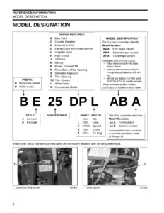
Because the same document covers the 20 Jet, the standard 20, the 25, and the 25 Marathon and 25 SeaPro variants, it is the single reference you need for the whole family rather than a narrow single-model sheet. Bore type differences, serial-number break points, stator type changes and carburetor model changes are all called out individually so you can confirm which procedure or specification applies to the exact motor in front of you.
File Details
- Manual type: Service / workshop manual
- Brand: Mercury Marine (Mercury and Mariner outboards)
- Models covered: 20 Jet, 20, 25, 25 Marathon, 25 SeaPro
- Document number: 90-826883 R2
- Revision: Revision No. 2
- Publication date: June 1998
- Language: English
- Format: PDF
- Page count: 357 pages
Chapters Covered
- Section 1 – Important Information: Specifications; Maintenance; General Information; Outboard Installation
- Section 2 – Electrical: Ignition; Charging and Starting System; Timing, Synchronizing and Adjusting; Wiring Diagrams
- Section 3 – Fuel System: Carburetor / Fuel Pump; Emissions
- Section 4 – Powerhead: Cylinder block and covers; crankshaft, pistons and flywheel; torque sequences; powerhead removal and disassembly; cleaning and inspection; cylinder bore; crankshaft; bearings; connecting rods; pistons; reed block; bleed system; thermostat; reassembly; installation; set-up and test-run; break-in
- Section 5 – Mid-Section
- Section 6 – Lower Unit: Gear Housing; Jet Drive
- Section 7 – Attachments / Control Linkage: Throttle / Shift Linkage; Tiller Handle; Side Shift
- Section 8 – Manual Starter
Taken as a whole, the manual gives a technician a complete teardown-and-rebuild path for the motor. It opens with the master specification table and the maintenance schedule, then moves into installation and rigging, and from there into each system in the order you would actually work: electrical and ignition first, then fuel and carburetion, then the powerhead as a complete unit, then the mid-section, gear housing and jet drive, and finally the control linkage and manual starter. Every section carries its own specification block, and the service procedures are written as numbered steps with the special tools and Quicksilver lubricants or sealants named where they are required.
Specifications and Adjustment Data
The master specification table covers the whole model range in one place. Horsepower is listed as 20 (14.9 kW) for the 20 Jet and 20, and 25 (18.7 kW) for the 25. Outboard weight is given for each shaft length – 114 lbs (52 kg) for the 15 in. (38 cm) leg, 117 lbs (53 kg) for the 20 in. (51 cm) leg, and 124 lbs (56 kg) for the 20 Jet. The powerhead is a two-cylinder, two-cycle unit of 24.4 cu. in. (400 cc) with a 2.362 in. (60 mm) stroke and a standard cylinder bore of 2.562 in. (65.01 mm), with a maximum taper or out-of-round of 0.003 in. (0.08 mm).
Crankshaft and connecting rod dimensions, piston diameter and ring end gap, crankshaft end play, and the piston-to-bore clearance figures are all tabulated, along with the two bore types used across the production run: chrome bores on serial numbers 0G202749 and below, which cannot be rebored or efficiently honed, and Mercosil bores on serial numbers 0G202750 and above, which can be rebored to 0.030 in. oversized. That distinction matters enormously when a block needs machine work, and it is spelled out clearly.
Beyond the master table, adjustment data is embedded in the sections where it is used: ignition timing curves and set-up timing values, idle and fast-idle speeds, wide-open-throttle RPM ranges, idle mixture screw preset turns, float level, main jet sizes by carburetor model and model year, high-altitude jetting chart, gear case lubricant capacity, spark plug gap, and the torque figures that appear beside nearly every fastener in the exploded illustrations.
Electrical, Ignition and Charging
The electrical section explains the alternator-driven capacitor discharge ignition system fitted to these motors in full: how the flywheel magnets, stator charge coils, trigger coil, switch box, ignition coils and spark plugs interact, and how the stop circuit shuts the engine down. Both the BLACK stator and the RED stator arrangements are described, and the manual identifies which models use each. It also covers the RPM limiter circuit in the 20 Jet RED stator ignition module, which interrupts one cylinder when RPM exceeds 6200 plus or minus 100 RPM.
The ignition section is also where the service technician gets the diagnostic procedure. Direct Voltage Adapter (DVA) test values for coil primary, switch box stop circuit, low-speed stator and high-speed stator are given for both electronic and mechanical spark advance systems, alongside resistance checks for the stator, trigger and ignition coils. A troubleshooting table maps symptoms such as no spark or weak spark on both cylinders, no spark on one cylinder, fluctuating timing, timing that will not advance, high-RPM misfire and hard starting when cold or hot to the likely faulty component, so the diagnosis is driven by measurement rather than guesswork.
The charging and starting section covers battery precautions, specific gravity and electrolyte readings, charging a discharged battery, winter storage, voltage regulator testing, alternator output testing and the full starting system including the starter solenoid, neutral start switch, starter motor disassembly, cleaning and inspection, armature testing, reassembly and a step-by-step starting circuit troubleshooting flow chart.
Fuel, Carburetion and Emissions
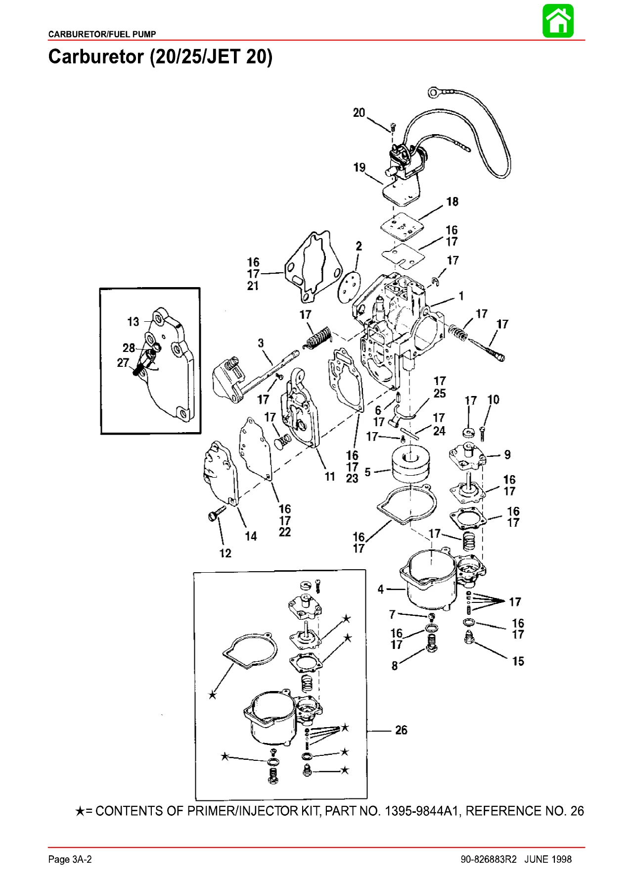
Carburetor coverage spans the WMC-series carburetors used across the model run, with exploded parts illustrations, removal and installation procedures, float adjustment, low-speed mixture screw adjustment, main jet identification, initial and final carburetor adjustment routines, and a high-altitude jet chart for operation between 2000 and 12000 feet. Fuel pump disassembly, cleaning, inspection and reassembly are included, as is the primer system with its diagnostic symptoms and the sight bowl fuel filter service.
A separate fuel system troubleshooting chapter lists symptoms – engine turns over but will not start or starts hard when cold, idles rough and stalls, runs uneven or surges, will not accelerate, floods, runs too rich, runs too lean, rough idle, fuel blowback out of the carburetor, or inability to reduce RPM to a slow idle – against the possible causes and the corrective action for each.
The emissions section explains hydrocarbon, carbon monoxide and nitrogen oxide formation, the stoichiometric air/fuel ratio, stratified versus homogenized charge, and the EPA certification requirements that apply to these engines, including the certification label layout and where it is located on the engine.
Powerhead, Lower Unit and Rigging
The powerhead section is the largest part of the book. It covers powerhead removal, full disassembly of the cylinder block, crankcase cover, exhaust manifold and covers, transfer covers, reed block and thermostat, then cleaning and inspection of every reusable component with the wear limits and serviceability checks that decide what gets replaced. Cylinder bore measuring and honing procedures are included, along with crankshaft straightness and bearing surface inspection, connecting rod alignment checking, piston and ring groove cleaning and measuring, reed opening checks and bleed system service.
Reassembly is handled with the same level of detail, including crankshaft carrier installation, roller bearing and thrust washer placement, piston pin and needle bearing installation, torque sequences for the exhaust cover, crankcase cover and cylinder block cover, and the final powerhead installation, set-up and test-run, and break-in procedures.
Rigging and installation are covered for both remote control and tiller handle configurations: transom height and mounting, steering cable and steering link rod installation, remote control and cable adjustment, shift and throttle cable installation and adjustment, remote wiring harness connection, battery cable connections, propeller installation, tilt pin adjustment and trim tab adjustment. Recommended lubricants and capacities, the inspection and maintenance schedule at each interval, flushing the cooling system, corrosion control anode service and storage preparation are all included, along with propeller selection guidance and the effect of weather, boat loading and hull condition on performance.
Diagnostics and Reference Material
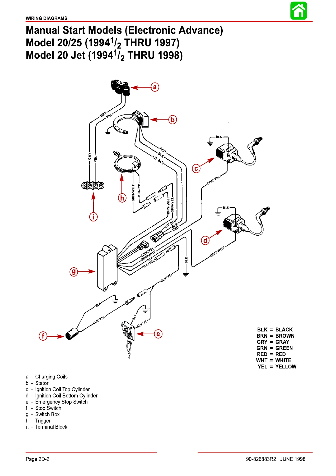
Throughout the manual, exploded views and cutaway illustrations accompany the procedures so component order, orientation and assembly relationships are unambiguous. Wiring diagrams cover manual start and electric start models in both electronic and mechanical spark advance versions, plus remote control wiring, tiller handle start button wiring, optional electrical accessories and the Commander remote control and panel mount control harnesses. Torque values are printed next to the fasteners in the illustrations as well as in the specification tables.
Why This Manual Matters for These Outboards
These 20 and 25 hp two-cycle outboards live in a serial-number-dependent world. The bore type changed mid-production, the stator type changed, the spark advance system changed from electronic to mechanical between model years, and the carburetor fitted depends on horsepower, model and year. Getting any of those wrong means ordering the wrong parts, applying the wrong adjustment, or damaging a block that cannot be rebored. This service manual resolves every one of those variables by listing them against the model and serial number ranges they apply to, so the procedure you follow is the correct one for the engine on your bench.
For an owner doing their own maintenance, it covers the routine work properly: gear case lubricant changes, water pump impeller replacement intervals, fuel system inspection, spark plug service, battery and charging system checks, lubrication points and winterisation. For a technician or a shop rebuilding a powerhead or resealing a gear case, it supplies the disassembly sequence, the inspection criteria, the torque figures and the assembly lubricants that determine whether the job lasts.
Get Instant Access
IMAGES PREVIEW
The Mercury Mariner 20 Jet 20 25 Marathon SeaPro Outboard Service Manual is delivered as an instant PDF download – no shipping, no waiting for a parcel, no software to install. Open it on a laptop or desktop in the workshop, on a tablet at the bench, or print the pages you need and take them to the boat. With 357 pages covering specifications, maintenance, electrical, fuel, powerhead, mid-section, lower unit and control linkage for the entire 20 Jet, 20, 25, 25 Marathon and 25 SeaPro range, this is the reference that lets you service, diagnose and repair these outboards correctly the first time.

Reviews
There are no reviews yet.