★ TRUSTED BY 321,897+ PROFESSIONALS WORLDWIDE
🏒
Trusted Business
Verified & Licensed
πŸ›‘οΈ
Virus Free Files
100% Safe Downloads
πŸ”’
Secure Payment
SSL Protected
⚑
Instant Delivery
Available Immediately
Sale!

Mercury 25 BigFoot FourStroke Service Manual 90-854785R2 – 2002 25HP 4-Stroke Outboard Repair

Original price was: $34.95.Current price is: $19.95.

Complete Mercury 25 BigFoot FourStroke service manual (90-854785R2, December 2001) covering the 25 HP 4-stroke outboard. Full electrical, fuel, powerhead, mid-section, lower unit, and control linkage procedures with specifications and diagrams.

⚑
Instant PDF Download
Available immediately
πŸ’Ύ
Save to Your Device
Download & keep forever
πŸ›‘οΈ
Antivirus Scanned
100% virus-free
🌍
Trusted Worldwide
175,000+ customers

Description

Mercury 25 BigFoot FourStroke Service Manual 90-854785R2

This is the complete service and repair manual for the Mercury 25 BigFoot FourStroke outboard, published by the Service Department of Mercury Marine under document number 90-854785R2 and dated December 2001. It is written for dealer mechanics and company service personnel servicing the 25 HP 4-stroke outboard, and it lays out every major system of the engine in dedicated sections with specifications, procedures, exploded views, and diagnostic references.

File Details

  • Manual type: Service / Repair Manual
  • Brand: Mercury Marine
  • Model: 25 BigFoot FourStroke (25 HP, 4-stroke)
  • Document number: 90-854785R2
  • Edition / date: December 2001
  • Language: English
  • File format: PDF
  • Page count: Approx. 471 pages

Chapters Covered

The manual is organised into nine top-level sections, each subdivided into the individual systems that make up the 25 BigFoot FourStroke. The Mercury 25 BigFoot FourStroke service manual covers:

  • Section 1 β€” Important Information
    • A β€” Specifications
    • B β€” Maintenance
    • C β€” General Information
    • D β€” Outboard Motor Installation
  • Section 2 β€” Electrical
    • A β€” Ignition
    • B β€” Charging & Starting System
    • C β€” Timing, Synchronizing & Adjusting
    • D β€” Wiring Diagrams
  • Section 3 β€” Fuel System
    • A β€” Fuel Pump
    • B β€” Carburetor
    • C β€” Emissions
  • Section 4 β€” Powerhead
    • A β€” Cylinder Head
    • B β€” Cylinder Block / Crankcase
    • C β€” Lubrication
  • Section 5 β€” Mid-Section
    • A β€” Clamp/Swivel Brackets & Driveshaft Housing
    • B β€” Power Trim
    • C β€” Gas Assist Manual Tilt
  • Section 6 β€” Lower Unit
    • Gear housing (driveshaft and propeller shaft)
    • Water pump, seals, bearings, clutch, and gear inspection
    • Pressure testing and gear housing installation
  • Section 7 β€” Attachments / Control Linkage
    • A β€” Throttle / Shift Linkage
    • B β€” Tiller Handle
  • Section 8 β€” Manual Starter
    • Recoil starter disassembly, rewind spring tension, and interlock cable adjustment
  • Section 9 β€” Color Diagrams
    • Remote control electric, tiller handle electric, gas assist, and manual start wiring diagrams
    • Oil flow diagram and water flow diagram

Across these sections the Mercury 25 BigFoot FourStroke repair manual gives a technician the full scope of the 4-stroke 25 HP outboard: ignition, charging and starting circuits with resistance and DVA test values, fuel pump and carburetor servicing with jet sizes and float height, cylinder head and valve service, cylinder block and crankcase assembly with torque sequences, lubrication system clearances, power trim hydraulics with flow diagrams, gear housing disassembly and reassembly with bearing and seal procedures, throttle and shift cable adjustment, tiller handle servicing, and recoil starter repair.

Specifications & Reference Data Included

Beyond procedures, the Mercury 25 BigFoot FourStroke service manual carries the reference values needed to complete the work correctly. These include:

  • Engine performance data β€” 25 HP (18.6 kW) at 5750 RPM, full throttle range 5500–6000 RPM, displacement 30.4 cu. in. (498 cc), compression ratio 9.8:1, firing order 1-2.
  • Ignition data β€” NGK DPR6EA-9 spark plug, 0.035 in. (1.0 mm) gap, 150 lb-in. (17 Nm) torque, capacitor discharge ignition with ECM-controlled timing, charge coil and crank position sensor resistance values.
  • Charging system data β€” 6 AMP manual alternator and 15 AMP electric alternator outputs with stator and battery charge coil resistances.
  • Fuel system data β€” fuel pump pressure 3–6 PSI, plunger stroke 0.23–0.38 in., carburetor main/pilot/idle jet sizes for standard and Bodensee models, float height 0.47–0.63 in. (12.0–16.0 mm).
  • Lubrication data β€” engine oil capacity either 3 quarts or 3 liters, oil pressure 30–40 PSI at 3000 RPM warm, oil pump clearances.
  • Torque specifications β€” an extensive table covering electrical, fuel, mid-section, adaptor plate, steering arm, power trim, and lower unit fasteners.
  • Gear housing data β€” 2.42:1 gear ratio, 14.9 fl. oz. (440 mL) capacity, 29-tooth forward gear, 12-tooth pinion, water pressure at idle and WOT.
  • Mid-section data β€” transom heights, steering pivot range, tilt pin positions, full tilt up angle, allowable transom thickness.
  • Propeller selection chart with diameter, pitch, blade count, material, boat weight, boat length, and Mercury part number.
  • Mercury/Quicksilver lubricants and sealants list with part numbers.
  • Cylinder head, valve, piston, ring, crankshaft, camshaft, and thermostat service limits.

Complete PDF Bookmark Tree

Complete Bookmarks

The complete bookmarks in the β€œMercury 25 BigFoot FourStroke Service Manual 90-854785R2 – 2002 25HP 4-Stroke Outboard Repair” are as follows:

coverp. 1
25 BigFoot FourStrokep. 1
Noticep. 2
Notice to Users of This Manualp. 2
Cleanliness and Care of Outboard Motorp. 3
Service Manual Outlinep. 4
1ap. 6
Section 1A – Specificationsp. 6
Table of Contentsp. 6
Specificationsp. 7
Propeller Information Chartp. 13
Mercury/Quicksilver Lubricants and Sealantsp. 14
Torque Specificationsp. 16
1bp. 20
Section 1B – Maintenancep. 20
Table of Contentsp. 20
Special Toolsp. 21
Inspection And Maintenance Schedulep. 21
Before Each Usep. 21
After Each Usep. 22
Every 100 Hours of Use or Once yearly, Whichever occurs firstp. 22
Every 300 Hours of Use or Three Yearsp. 22
Before Periods of Storagep. 22
Flushing The Cooling Systemp. 23
Fuel Systemp. 24
Fuel Line Filterp. 24
Fuel Line Inspectionp. 24
Corrosion Control Anodep. 25
Spark Plug Inspectionp. 26
Battery Inspectionp. 27
Fuse Replacement – Electric Start Modelsp. 28
Timing Belt Inspectionp. 28
Lubrication Pointsp. 29
Checking Power Trim Fluidp. 31
Changing Engine Oilp. 32
Oil Changing Procedurep. 32
Changing Oil Filterp. 33
Oil Fillingp. 33
Gear Case Lubricationp. 34
Draining Gear Casep. 34
Gear Case Lubricant Capacityp. 34
Checking Gear Case Lubricant Level and Refilling Gear Casep. 35
Storage Preparationp. 35
Fuel Systemp. 36
Protecting External Outboard Componentsp. 36
Protecting Internal Engine Componentsp. 36
Gear Casep. 36
Positioning Outboard for Storagep. 36
Battery Storagep. 36
1cp. 37
Section 1C – General Informationp. 37
Table of Contentsp. 37
Serial Number Locationp. 37
Conditions Affecting Performancep. 38
Weatherp. 38
Boatp. 39
Enginep. 40
Following Complete Submersionp. 41
Model 25 (4-Stroke) Powerhead Front Viewp. 42
Model 25 (4-Stroke) Powerhead Starboard Viewp. 43
Model 25 (4-Stroke) Powerhead Port Viewp. 44
Model 25 (4-Stroke) Powerhead Top Viewp. 45
Model 25 (4-Stroke) Powerhead Aft Viewp. 46
Propeller Selectionp. 47
Propeller Removal/Installationp. 48
Power Trim Systemp. 51
General Informationp. 51
Power Trim Operationp. 51
Trim β€œIn” Angle Adjustmentp. 52
Trim Tab Adjustmentp. 53
Compression Checkp. 53
Cylinder Leakage Testingp. 54
Analysisp. 54
Painting Proceduresp. 55
Decal Applicationp. 56
1dp. 58
Section 1D – Outboard Motor Installationp. 58
Table of Contentsp. 58
Installation Specificationsp. 58
Lifting Outboardp. 59
Installing Outboard – Non Thumb Screw Modelsp. 59
Installing Outboard – Thumb Screw Modelsp. 60
Steering Cablep. 61
Steering Cable Sealp. 62
Steering Link Rodp. 63
Wiring Harnessp. 64
Battery Cable Connectionsp. 65
Shift and Throttle Cablep. 66
Shift Cable Installationp. 66
Throttle Cable Installationp. 68
Trim-In Stop Adjustment – Power Trim Modelsp. 70
Trim Tab Adjustmentp. 70
2ap. 71
Section 2A – Ignitionp. 71
Table of Contentsp. 71
Specificationsp. 72
Special Toolsp. 73
Flywheelp. 74
Electrical Componentsp. 76
Ignition Descriptionp. 78
Ignition Component Descriptionp. 78
Electronic Control Module (ECM)p. 78
Crank Position Sensorp. 79
Stator Assemblyp. 79
Flywheel Assemblyp. 80
Ignition Coilp. 80
Ignition Test Proceduresp. 80
Ignition Troubleshootingp. 81
Tool: Multimeter/DVA Tester 91-99750A1p. 82
Ignition Diagnostic Proceduresp. 83
Recommended Testp. 84
Testing Ignition Componentsp. 86
Resistance Testsp. 86
Engine Coolant Temperature (ECT) Sensorp. 90
Flywheel Removal and Installationp. 91
Removalp. 91
Installationp. 92
Stator Removal and Installationp. 93
Timing Beltp. 94
(ECM) Removal and Installationp. 95
Ignition Coil Removal and Installationp. 96
Voltage Regulator Removal and Installationp. 96
Crank Position Sensor Removal and Installationp. 97
2bp. 98
Section 2B – Charging & Starting Systemp. 98
Table of Contentsp. 98
Specificationsp. 99
Special Toolsp. 99
Starter Motorp. 101
Batteryp. 103
Recommended Batteryp. 103
Operating Engine Without Batteryp. 103
Battery Charging System Troubleshootingp. 103
Battery Charging Systemp. 104
Description (15 Ampere)p. 104
Wiring Diagram (15 Ampere)p. 104
Alternator System Test (6 Ampere Stator)p. 105
Alternator System Test (15 Ampere Stator)p. 106
Stator Ohms Testp. 107
Regulator/Rectifier (P/N 854514-1) Diode Testp. 108
Analog Meterp. 108
Digital Meterp. 109
Starting System Componentsp. 110
Descriptionp. 110
Troubleshooting the Starting Circuitp. 110
Starter Solenoid Testp. 111
Starting Circuit Troubleshooting Flow Chartp. 112
Starter Motorp. 114
Removalp. 114
Disassemblyp. 114
Cleaning and Inspectionp. 116
Testingp. 117
Brush Replacementp. 119
Reassemblyp. 120
Installationp. 123
2cp. 124
Section 2C – Timing, Synchronizing & Adjustingp. 124
Table of Contentsp. 124
Specificationsp. 125
Special Toolsp. 126
Idle Speed Adjustmentp. 127
2dp. 128
Section 2D – Wiring Diagramsp. 128
Table of Contentsp. 128
Electric Start Power Trim Wiring Diagramp. 129
Electric Start Tiller Handle Wiring Diagramp. 130
Electric Start Wiring Diagramp. 131
Manual Start Wiring Diagramp. 132
3ap. 133
Section 3A – Fuel Pumpp. 133
Table of Contentsp. 133
Specificationsp. 133
Fuel Pump (USA S/N 0T408999 and Below, Belgium S/N 0P153499 and Below)p. 134
Fuel Pump ( USA S/N 0T409000 and Up, Belgium S/N 0P153500 and Up)p. 136
Fuel Pumpp. 138
Fuel Pump USA S/N 0T408999 and Belowp. 138
Fuel Pump Belgium S/N 0P153499 and Belowp. 138
Operationp. 138
Removalp. 138
Disassemblyp. 139
Inspectionp. 140
Reassemblyp. 141
Installationp. 143
Fuel Pumpp. 144
Fuel Pump USA S/N 0T409000 and Upp. 144
Fuel Pump Belgium S/N 0P153500 and Upp. 144
Operationp. 144
Removalp. 145
Disassemblyp. 146
Cleaning/Inspection/Repairp. 147
Check Valve Inspection/Replacementp. 147
Assemblyp. 148
Installationp. 150
3bp. 151
Section 3B – Carburetorp. 151
Table of Contentsp. 151
Specificationsp. 152
Special Toolsp. 152
Carburetor (USA S/N 0T408999 and Below, Belgium S/N 0T153499 and Below)p. 154
Carburetor (USA S/N 0T409000 and Up, Belgium S/N 0P153500 and Up)p. 156
Intakep. 158
Carburetor Adjustmentsp. 160
Carburetor Removalp. 161
Carburetor Removal USA S/N 0T408999 and Belowp. 161
Carburetor Removal Belgium S/N 0P153499 and Belowp. 161
Carburetor Removal USA S/N 0T409000 and Upp. 162
Carburetor Removal Belgium S/N 0P153500 and Upp. 162
Carburetor Disassemblyp. 163
Inspectionp. 166
Carburetor Assemblyp. 168
Carburetor Installationp. 171
Carburetor Installation USA S/N 0T408999 and Belowp. 171
Carburetor Installation Belgium S/N 0P153499 and Belowp. 171
Carburetor Installation USA S/N 0T409000 and Upp. 173
Carburetor Installation Belgium S/N 0P153500 and Upp. 173
3cp. 174
Section 3C – Emissionsp. 174
Table of Contentsp. 174
Exhaust Emissions Standardsp. 175
What Are Emissions?p. 175
Hydrocarbons – HCp. 175
Carbon Monoxide – COp. 175
Oxides of Nitrogen – NOxp. 175
Controlling Emissionsp. 175
Stoichiometric (14.7:1) Air/Fuel Ratiop. 176
Outboard Hydrocarbon Emissions Reductionsp. 176
Stratified Vs Homogenized Chargep. 177
Homogenized Chargep. 177
Stratified Chargep. 178
Emissions Informationp. 179
Manufacturer’s Responsibility:p. 179
Dealer Responsibility:p. 179
Owner Responsibility:p. 179
EPA Emission Regulations:p. 180
Manufacturer’s Certification Label:p. 181
Service Replacement Certification Labelp. 182
Removalp. 182
Date Code Identificationp. 182
Installationp. 182
Decal Location:p. 182
4ap. 183
Section 4A – Cylinder Headp. 183
Table of Contentsp. 183
Specificationsp. 184
Special Toolsp. 186
Cylinder Headp. 188
Intake/Exhaust Valvesp. 190
Camshaft/Oil Pumpp. 192
Torque Sequencep. 194
Valve Clearancep. 195
Checking Valve Clearancep. 195
Adjusting Valve Clearancep. 197
Preparation for Cylinder Head Removalp. 199
Cylinder Head Removalp. 200
Cylinder Head Disassemblyp. 201
Cleaning and Inspectionp. 203
Rocker Shaft and Rocker Armp. 203
Camshaftp. 204
Cylinder Headp. 206
Valvesp. 212
Valve Springsp. 213
Cylinder Head Reassemblyp. 214
Valve Installationp. 214
Camshaft Oil Seal Installationp. 216
Camshaft Installationp. 216
Rocker Arm Shaft Assemblyp. 218
Rocker Arm Shaft Installationp. 218
Cylinder Head Gasketp. 219
Cylinder Head Installationp. 219
Cylinder Head Cover Installationp. 220
4bp. 222
Section 4B – Cylinder Block/Crankcasep. 222
Table of Contentsp. 222
Specificationsp. 223
Special Toolsp. 224
Crankshaftp. 225
Cylinder Blockp. 227
Torque Sequencep. 229
Crankcase Coverp. 229
Exhaust Coverp. 230
Powerheadp. 230
Preparation for Powerhead Removalp. 231
Powerhead Removalp. 233
Removing Powerhead Componentsp. 234
Ignition Componentsp. 234
Charging and Starting System Componentsp. 234
Fuel Componentsp. 234
Harness and Battery Cable Removalp. 234
Oil Filter, Thermostat, and Exhaust Cover Removalp. 235
Cylinder Head Removalp. 236
Powerhead Disassemblyp. 236
Crankshaft and Piston Removalp. 236
Piston Disassemblyp. 239
Inspectionp. 240
Cylinder Borep. 240
Balance Pistonp. 241
Crankcase Cover Borep. 241
Pistonp. 242
Piston Pinp. 243
Piston Ringsp. 244
Crankshaftp. 245
Checking Main Bearing Clearancep. 245
Checking Connecting Rod Bearing Clearancep. 247
Thermostatp. 249
Oil Pressure Switchp. 249
Cylinder Block Reassemblyp. 250
Selecting New Main Bearingsp. 250
Main Bearing Installationp. 251
Selecting New Connecting Rod Bearingsp. 251
Installing Connecting Rod Bearingsp. 252
Connecting Rod Installationp. 252
Piston Ring Installationp. 253
Piston Installationp. 254
Crankshaft Installationp. 255
Crankcase Cover Installationp. 257
Cylinder Head Installationp. 259
Exhaust Cover Installationp. 259
Ignition Componentsp. 260
Charging and Starting System Componentsp. 260
Fuel Componentsp. 260
Powerhead Installationp. 261
Following Powerhead Installationp. 262
4cp. 264
Section 4C – Lubricationp. 264
Table of Contentsp. 264
Specificationsp. 265
Oil Pump Removalp. 265
Oil Pump Disassemblyp. 266
Cleaning and Inspectionp. 267
Oil Pump Assemblyp. 268
Oil Pump Installationp. 269
5ap. 270
Section 5A – Clamp/Swivel Brackets & Driveshaft Housingp. 270
Table of Contentsp. 270
Specificationsp. 270
Clamp Bracket (Remote Control)p. 271
Swivel Bracketp. 273
Swivel Bracket (Remote Control)p. 275
Driveshaft Housingp. 277
Adapter Platep. 279
Steering Armp. 281
5bp. 283
Section 5B – POWER TRIMp. 283
Table of Contentsp. 283
Special Toolsp. 284
Power Trimp. 286
Power Trim Mountingp. 288
Theory Of Operationp. 290
Adjustmentsp. 290
Trimming Characteristicsp. 290
Trailering Outboardp. 292
Tilting Outboard Up and Down Manuallyp. 292
Trim β€œIn” Angle Adjustmentp. 293
Power Trim Flow Diagrams – Trim Upp. 294
Power Trim Flow Diagrams – Tilt Upp. 296
Power Trim Flow Diagrams – Maximum Tiltp. 298
Power Trim Flow Diagrams – Trim Downp. 300
Power Trim Flow Diagrams – Shock Function Upp. 302
Power Trim Flow Diagrams – Shock Return Functionp. 304
Power Trim Flow Diagrams – Manual Tiltp. 306
Troubleshootingp. 308
Preliminary Checksp. 308
Hydraulic System Troubleshooting Flow Chartp. 309
Troubleshooting the Power Trim Electrical Systemp. 313
Power Trim System Removalp. 315
Testing Power Trim System With Test Gauge Kit (91-52915A6)p. 318
β€œUP” Pressure Checkp. 318
β€œDOWN” Pressure Checkp. 321
Disassemblyp. 323
Shock Rod Disassemblyp. 324
Memory Piston Removalp. 327
Trim Motor Removalp. 328
Oil Pump Removalp. 329
Tilt Relief Valve Removalp. 330
Suction Seat Removalp. 331
Pilot Check Valve Assembly Removalp. 332
Cleaning/Inspection/Repairp. 333
Reassemblyp. 334
Power Trim Reassemblyp. 336
Tilt Relief Valve Reassemblyp. 336
Suction Seat Reassemblyp. 337
Pilot Check Valve Reassemblyp. 338
Oil Pump Reassemblyp. 339
Trim Motor Reassemblyp. 340
Shock Rod Reassemblyp. 341
Shock Rod Installationp. 344
Manual Release Valve Installationp. 345
Bleeding Power Trim Unitp. 345
Power Trim System Installationp. 346
5cp. 349
Section 5C – Gas Assist Manual Tiltp. 349
Table of Contentsp. 349
Clamp Bracketp. 350
Hydraulic Assist Adjustmentsp. 352
Manual Trim System Removalp. 353
Manual Trim System Installationp. 355
6p. 358
Lower Unitp. 358
Table of Contentsp. 358
Specificationsp. 359
Special Toolsp. 359
Gear Housing (Driveshaft) (2.42:1 Gear Ratio)p. 363
Gear Housing (Propeller Shaft) (2.42:1 Gear Ratio)p. 365
General Service Recommendationsp. 367
Bearingsp. 367
Sealsp. 367
Draining and Inspecting Gear Lubricantp. 368
Gear Housing Removalp. 369
2-Stroke Modelsp. 369
4-Stroke Modelsp. 370
Disassemblyp. 372
Water Pumpp. 372
Water Pump Sealsp. 378
Inspectionp. 380
Upper Drive Shaft Bearingp. 380
Pinion Gear Bearingp. 381
Pinion Gearp. 381
Forward Gearp. 381
Shift Shaftp. 384
Propeller Shaft Disassemblyp. 385
Propeller Shaft and Carrier Inspectionp. 386
Clutchp. 386
Cam Followerp. 386
Reverse Gearp. 387
Reverse Gear Bearingp. 387
Bearing Carrierp. 389
Gear Housing Reassemblyp. 392
Shift Shaft Assemblyp. 393
Pinion Bearing Racep. 394
Forward Gearp. 395
Pinion Gear/Drive Shaft Assemblyp. 396
Propeller Shaftp. 397
Bearing Carrierp. 399
Water Pumpp. 401
Gear Housing Pressure Testp. 403
Gear Housing Installationp. 404
Filling Gear Housing with Lubricantp. 404
Installing Gear Housing to Drive Shaft Housingp. 405
Trim Tab Adjustment and Replacementp. 408
7ap. 409
Section 7A – Throttle/Shift Linkagep. 409
Table of Contentsp. 409
Linkagep. 410
Shift Cable Installationp. 412
Throttle Cable Installationp. 414
7bp. 416
Section 7B – Tiller Handlep. 416
Table of Contentsp. 416
Tiller Handlep. 417
Throttle Cable Adjustmentp. 419
Tiller Handle Assembly Removalp. 421
Tiller Handle Disassemblyp. 423
Tiller Handle Reassemblyp. 426
Tiller Handle Installationp. 432
8p. 435
Manual Starterp. 435
Table of Contentsp. 435
Manual Starterp. 436
Manual Starter Removalp. 438
Manual Starter Disassemblyp. 439
Cleaning and Inspectionp. 442
Rewind Starter Reassemblyp. 443
Adjusting Rewind Spring Tensionp. 445
Manual Starter Installationp. 450
Interlock Cable Adjustmentp. 451
9p. 452
Color Diagramsp. 452
Table of Contentsp. 452
25 Bigfoot (4-Stroke) Remote Control Electric 2002 Model Year USA S/N 0G760300 and up Belguim S/N 0P059000 and upp. 454
25 Bigfoot (4 Stroke) Tiller Handle Electric 2002 Model Year USA S/N 0G760300 and up Belguim S/N 0P059000 and upp. 457
25 Bigfoot (4 Stroke) Remote Control Electric (Gas Assist) 2002 Model Year USA S/N 0G760300 and up Belguim S/N 0P059000 and upp. 460
25 Bigfoot (4 Stroke) Tiller Handle Manual 2002 Model Year USA S/N 0G760300 and up Belguim S/N 0P059000 and upp. 463
25 (4-Stroke) Oil Flow Diagramp. 466
25 (4-Stroke) Water Flow Diagramp. 469

Diagnostic Coverage

Diagnostics are a significant part of this 25 BigFoot FourStroke workshop manual. The ignition section includes a full troubleshooting table organised by symptom β€” no spark on both cylinders, no spark on one cylinder, weak spark, timing that will not advance, engine misfire at high RPM, hard starting cold and hot, engine not running over 2000 RPM, and engine surging over 6200 RPM β€” with probable causes and recommended test numbers. The charging system troubleshooting covers battery condition, stator ohm tests, regulator/rectifier diode and SCR tests for both analog and digital meters, and the starter circuit is presented as a step-by-step flow chart with test points identified on a diagram. Power trim hydraulic troubleshooting is broken into two flow charts β€” outboard not holding tilted position, and trim system leaking down with manual release valve closed. An electrical troubleshooting table for the power trim system isolates switch, relay, fuse, and motor faults by symptom.

Diagrams, Illustrations, and Wiring

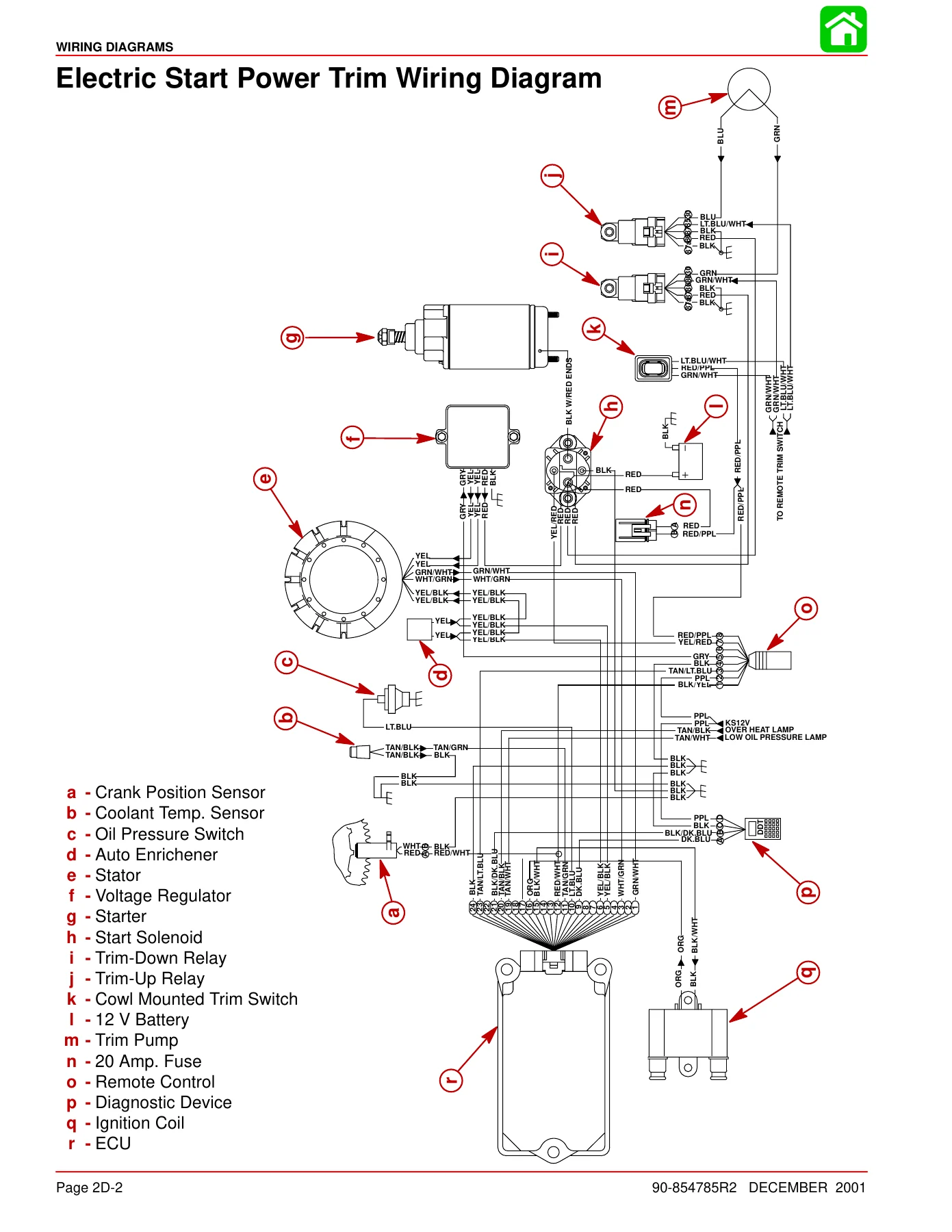
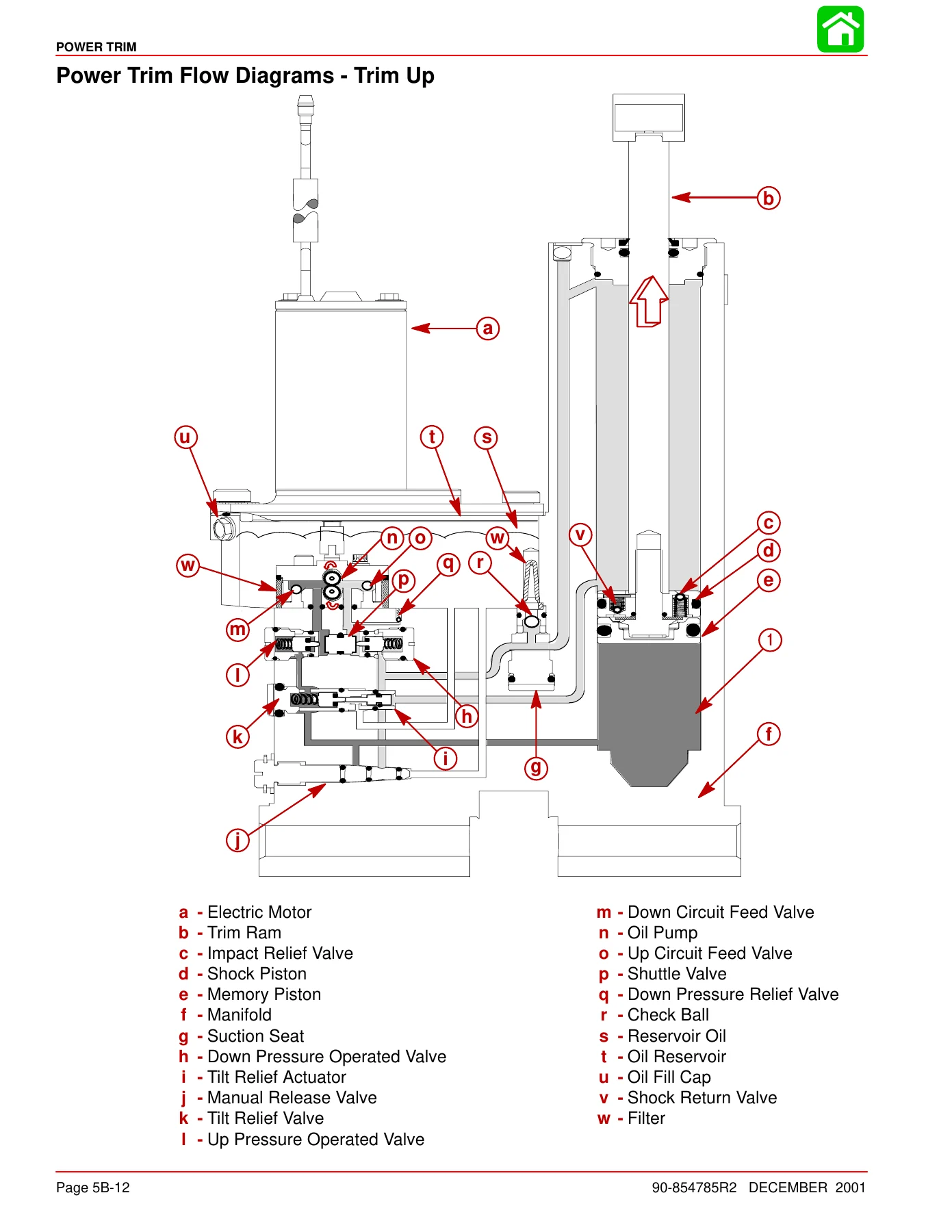
The Mercury 25 BigFoot FourStroke repair manual is heavily illustrated. The powerhead is shown in front, starboard, port, top, and aft views with every hose, sensor, fitting, and connector identified. Exploded parts drawings accompany the fuel pump, carburetor, intake, cylinder head, camshaft, oil pump, power trim, gear housing, propeller shaft, tiller handle, and manual starter procedures. Wiring diagrams are provided for remote control electric, tiller handle electric, remote control electric with gas assist, and tiller handle manual configurations, with a dedicated color diagrams section for 2002 model year engines. Power trim flow diagrams show trim up, tilt up, maximum tilt, trim down, shock function up, shock function return, and manual tilt. Oil flow and water flow diagrams close out the manual.

What This Manual Lets You Do

With the Mercury 25 BigFoot FourStroke service manual 90-854785R2 on hand, a technician or owner can carry out the full range of repair and maintenance work on this specific 4-stroke 25 HP outboard. That includes ignition system testing and component replacement, charging and starting system diagnosis, timing belt and stator service, fuel pump and carburetor overhaul with correct jetting, cylinder head removal and valve adjustment, powerhead disassembly with piston and crankshaft inspection, lubrication system service, power trim hydraulic repair and pressure testing, lower unit disassembly with bearing and seal replacement, propeller shaft and clutch service, shift and throttle cable adjustment, tiller handle repair, and manual starter rewind servicing.

What matters is that the values are the right ones. A 4-stroke outboard is unforgiving of wrong clearances, wrong torque, and wrong jetting β€” the difference between a clean-running engine and a damaged one often comes down to a single specification. The Mercury 25 BigFoot FourStroke service manual supplies the factory specifications, the torque sequences, the clearances, and the resistance values that the job requires, along with the exploded views and wiring diagrams that show how the parts actually go together.

IMAGES PREVIEW

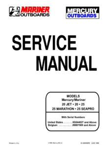
Mercury 25 BigFoot FourStroke Service Manual 90-854785R2 - 2002 25HP 4-Stroke Outboard Repair β€” PDF page 1 preview
Mercury 25 BigFoot FourStroke Service Manual 90-854785R2 - 2002 25HP 4-Stroke Outboard Repair β€” PDF page 129 preview
Mercury 25 BigFoot FourStroke Service Manual 90-854785R2 - 2002 25HP 4-Stroke Outboard Repair β€” PDF page 294 preview

The file is delivered as an instant PDF download β€” no shipping, no waiting. It opens on any device, can be printed for the workshop bench, and the pages you use most can be kept to hand while you work.

Reviews

There are no reviews yet.

Be the first to review “Mercury 25 BigFoot FourStroke Service Manual 90-854785R2 – 2002 25HP 4-Stroke Outboard Repair”

What Our Customers Say

β˜…β˜…β˜…β˜…β˜… Live reviews from customers
Loading customer reviews...
0
    0
    Your Cart
    Your cart is emptyReturn to Shop
    πŸ›’
    Recently Purchased
    πŸ•’ verified order