
Mercury 135 150 175 200 225 HP Outboard Service Manual – 1992 & Newer PDF
Original price was: $42.95.$26.95Current price is: $26.95.
Complete Mercury Marine service manual for 135, 150, 175, 200, and 225 HP V6 outboards from 1992 and newer (serial 0D082000+). Covers ignition, fuel injection, powerhead, mid-section, lower unit, and more in 800+ pages.
Description
Mercury 135 150 175 200 225 HP Outboard Service Manual
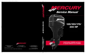
This is the comprehensive Mercury 135 150 175 200 225 HP Outboard Service Manual published by the Mercury Marine Service Department. It covers 1992 and newer V6 outboard models including the 135, 150, 150 XR6, 150 Magnum III, 150 EFI, 175, 175 EFI, 200, 200 EFI, 150/200/225 Pro Max, and 150/200/225 Super Magnum with serial numbers 0D082000 and above. This factory-issued service manual is the same reference used by Mercury Marine dealers and service personnel to diagnose, repair, and maintain these outboards.
File Details
- Manual Type: Outboard Service Manual
- Brand: Mercury Marine
- Models Covered: 135, 150, 150 XR6, 150 Magnum III, 150 EFI, 175, 175 EFI, 200, 200 EFI, 150/200/225 Pro Max, 150/200/225 Super Magnum
- Serial Number Range: 0D082000 and Above
- Model Years: 1992 and Newer
- Language: English
- File Format: PDF
- Document Number: 90-824052R2
- Publication Date: September 1997
- Pages: 800+
Chapters Covered
The Mercury 135 150 175 200 225 outboard service manual is organized into seven major sections, each diving deep into the systems and components that keep these V6 outboards running:
- Section 1 — Important Information
- Specifications
- Maintenance schedules and procedures
- General information, serial number locations, and conditions affecting performance
- Outboard installation, steering, and control setup
- Section 2 — Electrical
- Ignition system, stator, trigger, coils, and switch boxes
- Battery charging and starting system
- Timing, synchronizing, and adjusting
- Wiring diagrams
- Section 3 — Fuel System
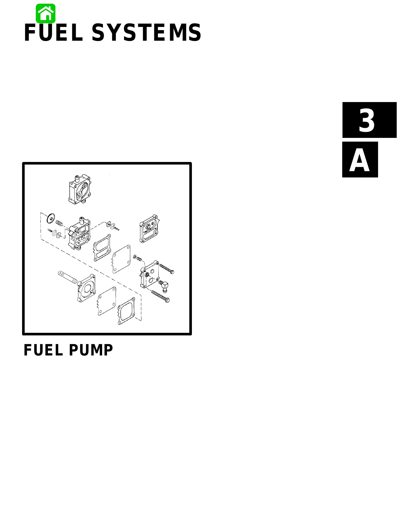
- Fuel pump
- Carburetors (WMH and WMV series)
- Fuel injection 1995 and prior
- Fuel injection 1996 and up
- Oil injection system
- Emissions and exhaust emissions standards
- Section 4 — Powerhead
- Cylinder block, end caps, crankshaft, pistons, and connecting rods
- Exhaust manifold, reed block, and cylinder heads
- Powerhead removal, disassembly, cleaning, inspection, and reassembly
- Break-in procedures
- Section 5 — Mid-Section
- Clamp/swivel brackets and drive shaft housing
- Power trim systems (square motor and round motor designs)
- Hydraulic system operation and troubleshooting
- Trim motor repair and electrical tests
- Section 6 — Lower Unit
- Right hand rotation gear housing
- Left hand rotation (counter rotation) gear housing
- 1.78:1 ratio gear housing
- Right hand non-ratcheting
- Left hand non-ratcheting
- Jet outboards
- Section 7 — Attachments/Control Linkage
- Outboard installation on transom
- Ride-Guide steering cable and attaching kits
- Remote control installation and cable adjustment
- Battery and fuel connections
What This Mercury Outboard Service Manual Covers
This Mercury outboard service manual is a complete reference for anyone maintaining, repairing, or rebuilding these V6 outboards. Whether you’re a professional marine mechanic or a boat owner who prefers to handle your own maintenance, this manual provides the step-by-step procedures, specifications, and diagnostic information needed to do the job right.
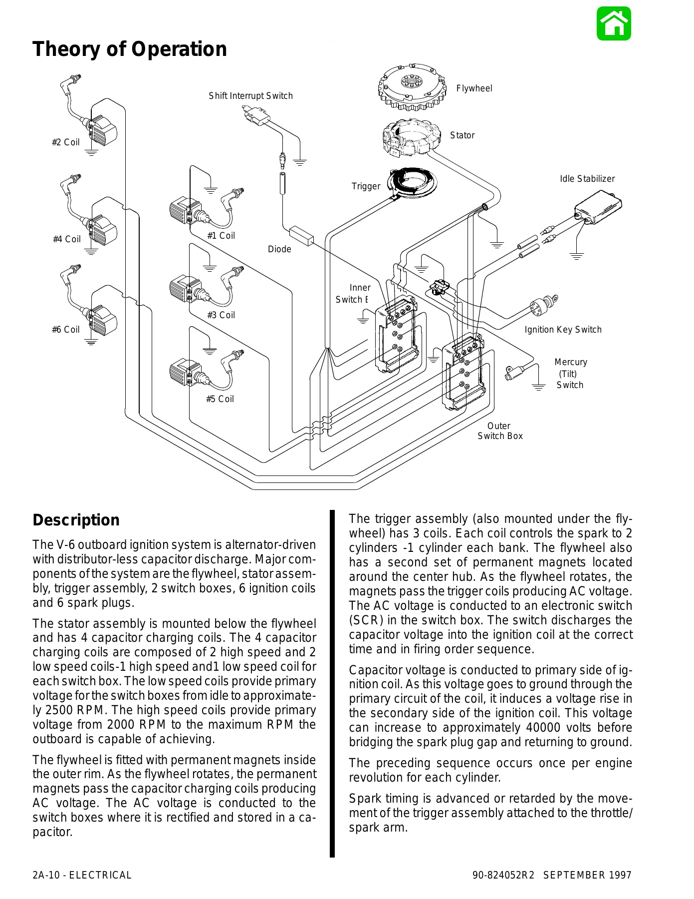
The manual covers all major systems in detail. The ignition section walks through the capacitor discharge ignition system with stator, trigger, switch box, and ignition coil testing procedures — including DVA voltage specifications and troubleshooting charts. The fuel system section covers both carbureted and EFI models, with carburetor disassembly, jet specifications, fuel pump testing, oil injection setup, and comprehensive EFI diagnostics for the 1995 and prior and 1996 and up systems.
Powerhead coverage includes complete disassembly and reassembly procedures with torque sequences, cleaning and inspection criteria, piston and ring specifications, and crankshaft service data. The mid-section section handles power trim hydraulics, trim motor repair, and electrical troubleshooting for both square motor and round motor designs. Lower unit coverage spans standard rotation, counter rotation, non-ratcheting, and jet drive gear cases, with pinion depth, forward gear backlash, and reverse gear backlash specifications for each ratio.
Who This Manual Is For
This Mercury 135 150 175 200 225 service manual is intended for Mercury Marine dealers’ mechanics and company service personnel, as well as experienced boat owners and independent marine technicians. The procedures assume familiarity with marine engine service and the use of common hand tools and special Mercury Marine tools. Torque specifications, service limits, and adjustment values are provided throughout to ensure repairs are done to factory standards.
Why You Need This Manual
Working on a V6 outboard without the correct service information can lead to costly mistakes — improper torque values, incorrect gear lash settings, or missed diagnostic steps that turn a simple repair into a major overhaul. This manual gives you the exact procedures and specifications that Mercury Marine published for these engines, so you can diagnose problems accurately and complete repairs with confidence. From routine maintenance like water pump impeller replacement and gear lubricant changes to complex jobs like powerhead disassembly and EFI troubleshooting, the answers are in these pages.
Get Instant Access
IMAGES PREVIEW
This Mercury 135 150 175 200 225 HP Outboard Service Manual is delivered as an instant PDF download after payment. No shipping, no waiting for a physical book to arrive. The file works on any device — computer, tablet, or smartphone — and you can print the pages you need for the job at hand. Whether you’re servicing a 150 EFI on a center console or rebuilding the powerhead on a 200 Pro Max, this manual puts the full scope of Mercury Marine service information at your fingertips.
Reviews
There are no reviews yet.