
Hidea HDF6 Outboard Service Manual March 2017 – F6 4-Stroke Workshop PDF
Original price was: $29.95.$17.95Current price is: $17.95.
Complete Hidea HDF6 F6 4-stroke outboard service manual from March 2017. Covers engine, lower unit, electrical, fuel, bracket, maintenance, and wiring diagrams for professional repair and service.
Description
Hidea HDF6 Outboard Service Manual – March 2017 – F6 4-Stroke Workshop PDF
This Hidea HDF6 Outboard Service Manual is the definitive workshop guide for the HDF6 / F6 4-stroke outboard motor, published in March 2017. Whether you are a dealer-trained mechanic or an experienced owner performing your own maintenance, this manual provides the complete procedures, specifications, and technical illustrations needed to service, troubleshoot, and repair the HDF6 outboard correctly and safely. From routine maintenance like gear oil changes and valve clearance adjustments to major overhauls of the power unit, lower unit, and bracket assembly, the Hidea HDF6 service manual gives you the same reference material used in professional workshops.
File Details
- Manual Type: Service Manual
- Brand: Hidea
- Model: HDF6 (F6)
- Document Title: F6HD SERVICE MANUAL
- Date: March 2017 (2017-03-20)
- Language: English
- Page Count: 202
- File Format: PDF
Chapters Covered
- General Information — Safety While Working, Rotating Parts, Hot Parts, Electric Shock, Propeller Handling, Gasoline Handling, Ventilation, Self-Protection, Working with Crane, Parts/Lubricants/Sealants, Special Service Tools, Tightening Torque, Non-Reusable Parts, Disassembly and Assembly
- How to Use This Manual — Manual Format, Abbreviation, Lubricant/Sealant/Thread Locking Agent Symbols, Special Service Tool
- Specification — Model Feature, Model Data, Electrical Technical Data, Fuel System Technical Data, Power Unit Technical Data, Lower Unit Technical Data, Specified Tightening Torque, General Tightening Torque
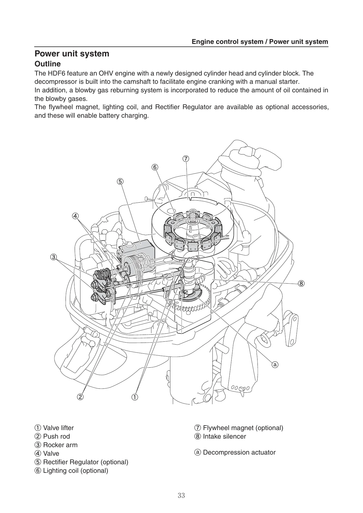
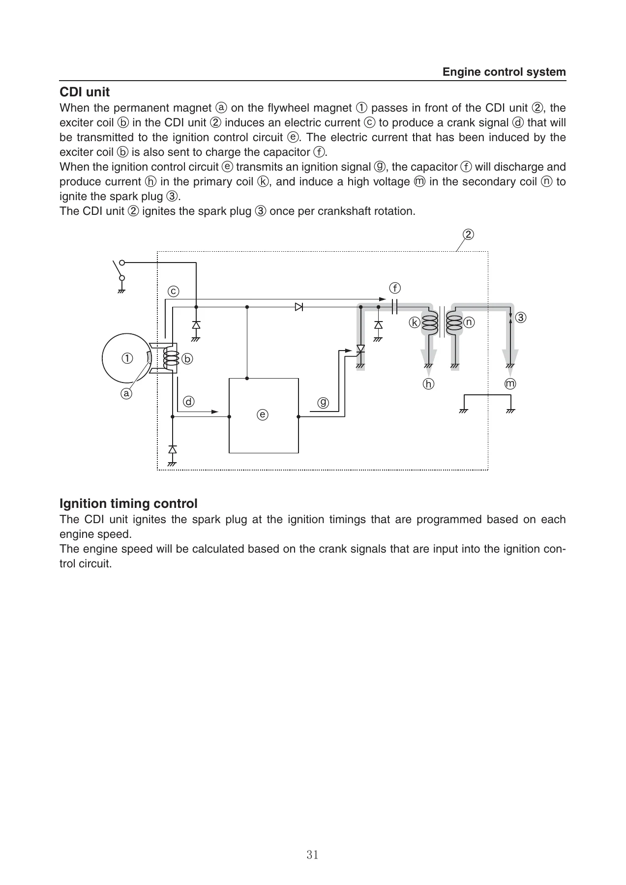
- Technical Features and Description — Engine Control System (CDI Unit, Ignition Timing Control, Ignition Cut-Off Control), Power Unit System (Automatic Decompressor, Blowby Gas Reburning System, Lighting Coil), Fuel System (Carburetor, Built-In Primer Pump), Lubrication System, Tilt System (Reverse Lock System), Lubrication Diagram, Cooling Flow Diagram, Intake and Exhaust Flow Diagram
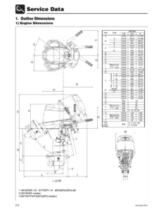
- Rigging Information — Outboard Motor Installation, Dimension, Exterior HDF6, Clamp Bracket, Uncrating Procedure, Outboard Motor Mounting, Installing the Charging System, Installing the Battery, Rigging Recommendations, Battery Requirement, Propeller Selection, Propeller Size, Selection
- Troubleshooting — Outboard Motor Troubleshooting, Troubleshooting Procedure, Troubleshooting the Power Unit, Troubleshooting the Lower Unit
- Electrical System — Electrical Component and Wiring Harness Routing, Checking the Electrical Component, Measuring the Peak Voltage, Using the Digital Tester, Charging Unit and Component, Checking the Lighting Coil, Checking the Rectifier Regulator, Ignition Unit and Component, Checking the Ignition Spark, Checking the Spark Plug Cap, Checking the Engine Shut-Off Switch
- Fuel System — Hose Routing, Fuel Hose, Blowby Hose/Oil Return Hose/Cooling Water Hose, Fuel Tank, Removing the Fuel Tank, Removing the Primer Pump, Checking the Fuel Tank, Checking the Fuel Joint, Checking the Fuel Strainer, Checking the Primer Pump, Installing the Primer Pump, Installing the Fuel Tank, Intake Silencer, Removing the Throttle Cable and Throttle Link, Removing the Carburetor, Installing the Carburetor, Installing the Throttle Cable and Throttle Link, Adjusting the Throttle Cable and Throttle Link, Carburetor, Disassembling the Carburetor, Checking the Carburetor, Assembling the Carburetor, Fuel Pump, Removing the Fuel Pump, Checking the Fuel Pump, Disassembling the Fuel Pump, Checking the Diaphragm and Valve, Assembling the Fuel Pump, Installing the Fuel Pump
- Power Unit — Power Unit (Check and Adjustment), Checking the Compression Pressure, Checking the Ignition Timing, Checking the CDI Unit Air Gap, Adjusting the CDI Unit Air Gap, Checking the Valve Clearance, Adjusting the Valve Clearance, Manual Starter, Removing the Manual Starter, Disassembling the Manual Starter, Checking the Manual Starter, Checking the Spiral Spring, Assembling the Manual Starter, Installing the Manual Starter, Adjusting the Start-In-Gear Protection Cable, Measuring the Starter Rope, Power Unit Assembly, Removing the Power Unit, Installing the Power Unit, Flywheel Magnet, Removing the Flywheel Magnet, Installing the Flywheel Magnet, Crankcase, Removing the Oil Pump, Removing the Oil Seal Housing, Removing the Crankcase, Checking the Crankcase, Checking the Rotor Assembly, Checking the Oil Strainer, Checking the Oil Seal Housing, Installing the Crankcase, Installing the Oil Pump, Installing the Oil Seal Housing, Cylinder Head, Removing the Cylinder Head, Disassembling the Cylinder Head, Checking the Cylinder Head, Checking the Rocker Arm, Checking the Push Rod, Checking the Valve Spring, Checking the Valve, Checking the Valve Guide, Replacing the Valve Guide, Checking the Valve Seat, Refacing the Valve Seat, Checking the Spark Plug, Checking the Thermostat Cover Anode, Checking the Thermostat, Assembling the Cylinder Head, Installing the Cylinder Head, Cylinder Block, Disassembling the Cylinder Block, Checking the Piston Diameter, Checking the Cylinder Bore, Checking the Piston Ring, Checking the Piston Ring End Gap, Checking the Piston Ring Groove, Checking the Piston Ring Side Clearance, Checking the Piston Pin Boss Inside Diameter, Checking the Piston Pin Diameter, Checking the Connecting Rod Small End Inside Diameter and Big End Inside Diameter, Checking the Crankshaft, Checking the Connecting Rod Oil Clearance, Checking the Cylinder Block, Checking the Camshaft, Checking the Valve Lifter, Assembling the Cylinder Block
- Lower Unit — Lower Unit, Removing the Lower Unit (S-Transom Model), Removing the Lower Unit (L-Transom Model), Disassembling the Extension (L-Transom Model), Checking the Propeller, Checking the Lower Unit Anode, Water Pump and Shift Rod, Removing the Water Pump and Shift Rod, Checking the Water Pump, Checking the Shift Rod, Propeller Shaft Housing, Removing the Propeller Shaft Housing Assembly, Disassembling the Propeller Shaft Assembly, Disassembling the Propeller Shaft Housing Assembly, Checking the Propeller Shaft, Checking the Dog Clutch, Checking the Propeller Shaft Housing, Checking the Reverse Gear, Assembling the Propeller Shaft Assembly, Assembling the Propeller Shaft Housing Assembly, Drive Shaft and Lower Case, Removing the Drive Shaft, Disassembling the Lower Case, Checking the Pinion, Checking the Forward Gear, Checking the Drive Shaft, Checking the Lower Case, Assembling the Lower Case, Installing the Drive Shaft, Installing the Propeller Shaft Housing Assembly (S-Transom Model), Installing the Propeller Shaft Housing Assembly (L-Transom Model), Installing the Water Pump and Shift Rod, Checking the Lower Unit for Air Leakage, Assembling the Extension (L-Transom Model), Installing the Lower Unit (S-Transom Model), Installing the Lower Unit (L-Transom Model)
- Bracket Unit — Tiller Handle, Disassembling the Tiller Handle, Assembling the Tiller Handle, Bottom Cowling, Disassembling the Bottom Cowling, Assembling the Bottom Cowling, Upper Case and Shift Lever, Removing the Shift Lever, Removing the Upper Case, Checking the Upper Case, Installing the Upper Case, Installing the Shift Lever, Clamp Bracket, Disassembling the Clamp Bracket, Assembling the Clamp Bracket
- Maintenance — Outline, Maintenance Interval Chart, Predelivery Check, Checking the Battery, Checking the Cooling Water Pilot Hole, Checking the Engine Oil Level, Checking the Engine Shut-Off Switch, Checking the Fuel System, Checking the Gear Oil Level, Checking the Gear Shift and Throttle Operation, Checking the Outboard Motor Mounting Height, Checking the Steering System, Checking the Throttle Cable, Checking the Tilt System, Starting the Engine, Test Run, Break-In, After Test Run, General Periodic Maintenance, Checking the Anode, Checking the Battery, Checking the Cooling Water Passage, Checking the Engine Idle Speed, Changing the Engine Oil, Checking the Engine Oil Level, Checking the Engine Shut-Off Switch, Checking the Fuel Joint and Fuel Hoses, Checking the Fuel Strainer, Changing the Gear Oil, Checking the Gear Oil Level, Checking the Ignition Timing, Lubricating the Outboard Motor, Checking the Propeller, Checking the Spark Plug, Checking the Spark Plug Cap, Checking the Thermostat, Adjusting the Throttle Link Rod and Throttle Cable, Checking the Top Cowling, Checking the Valve Clearance, Checking the Water Pump
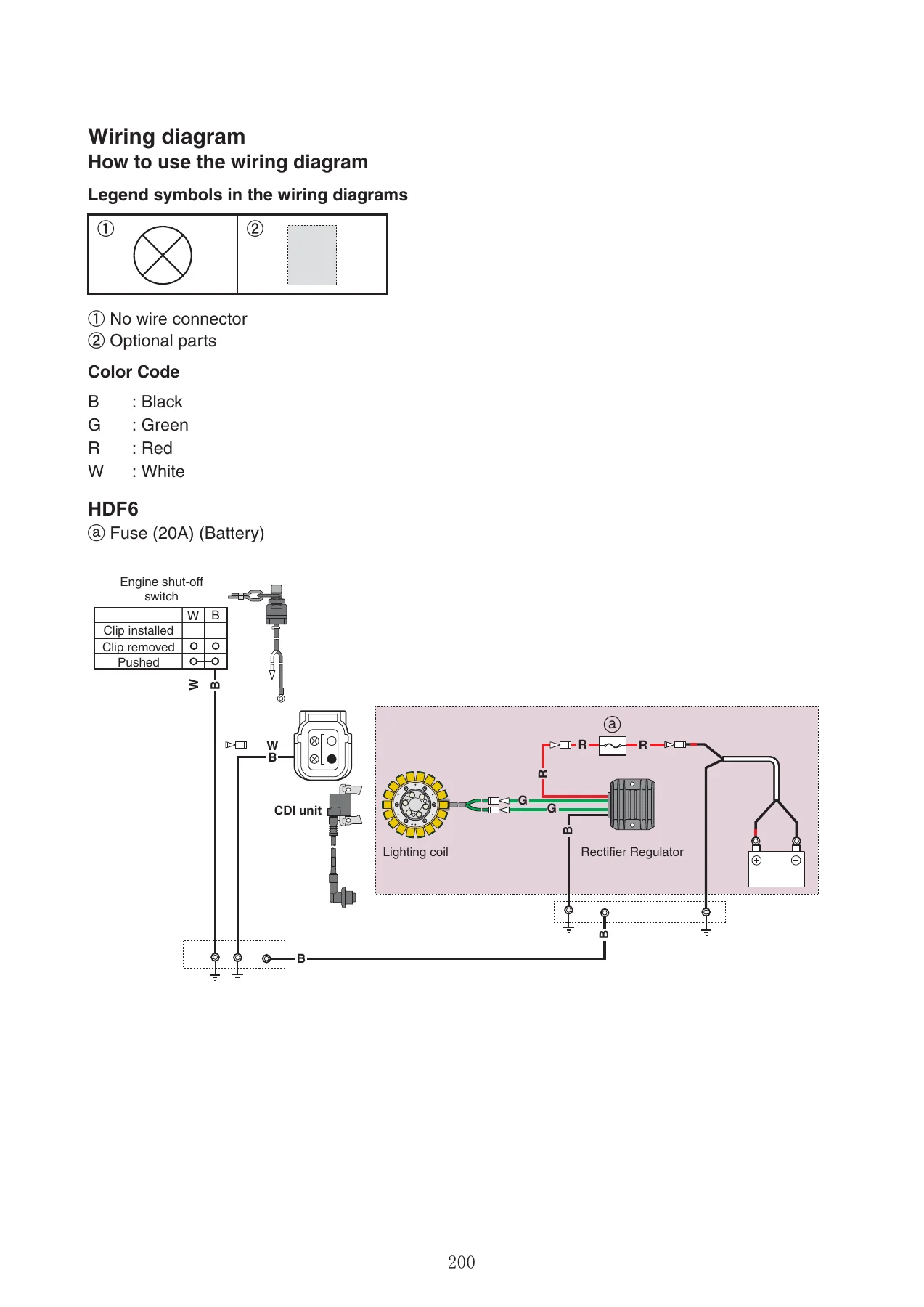
- Appendix — Wiring Diagram, How to Use the Wiring Diagram, HDF6
IMAGES PREVIEW
The Hidea HDF6 service manual is far more than a basic owner’s guide. It is a full workshop reference that walks through every major assembly on the F6 4-stroke outboard, with exploded diagrams, cross-referenced torque values, and step-by-step removal and installation procedures. The specification chapter alone gives you the exact tolerances, clearances, and service limits needed to determine whether a component is within spec or requires replacement. The troubleshooting chapter is structured to help you diagnose symptoms systematically—starting from the most likely causes and working toward the less common ones—so you can avoid unnecessary parts swapping and get to the root cause efficiently. Whether you are rebuilding a carburetor, replacing a water pump impeller, adjusting valve clearance, or tracing an electrical fault through the CDI system, this manual provides the technical foundation to do the job correctly.
What This Manual Enables You to Do
- Perform complete engine diagnosis using the compression pressure check, ignition timing check, and CDI unit air gap measurement procedures
- Adjust valve clearance and verify camshaft, rocker arm, and push rod condition against factory specifications
- Disassemble and reassemble the power unit, cylinder head, cylinder block, crankcase, and oil pump with correct torque sequences
- Service the carburetor including float height adjustment, pilot screw setting, and jet inspection
- Remove, inspect, and reinstall the lower unit, water pump, propeller shaft housing, drive shaft, and forward/reverse gears
- Diagnose and repair electrical faults in the charging system, lighting coil, Rectifier Regulator, and CDI ignition circuit
- Perform predelivery checks and scheduled maintenance per the maintenance interval chart
- Interpret the complete HDF6 wiring diagram for troubleshooting and accessory installation
- Service the manual starter, including spiral spring replacement and start-in-gear protection cable adjustment
- Disassemble and assemble the bracket unit, tiller handle, bottom cowling, and clamp bracket
Why the Hidea HDF6 Service Manual Matters
Outboard motors operate in a harsh marine environment where incorrect service procedures or wrong torque values can lead to premature failure, water intrusion, or catastrophic engine damage. The Hidea HDF6 Outboard Service Manual eliminates guesswork by providing the exact specifications and sequences that Hidea engineers designed for the F6 platform. From the torque sequence for the cylinder head bolts to the float height on the carburetor, every critical measurement and procedure is documented. This is especially important for a single-cylinder 4-stroke engine where valve clearance, compression, and lubrication are tightly interrelated—an error in one area can affect the entire power unit. Having the correct service reference also helps you avoid damaging non-reusable components like gaskets, O-rings, oil seals, cotter pins, and clips, which the manual explicitly identifies throughout.
Whether you are maintaining a fleet of rental outboards, servicing a customer’s HDF6, or restoring your own F6 4-stroke, this manual gives you the confidence to work accurately and efficiently. The troubleshooting charts alone can save hours of diagnostic time by pointing you toward the most probable causes first, and the exploded diagrams make reassembly straightforward even for complex assemblies like the manual starter or propeller shaft housing.
Instant PDF Delivery
This Hidea HDF6 service manual is delivered as an instant PDF download after payment—no shipping, no waiting. You can access it on any device, including laptops, tablets, and smartphones, and print individual pages or entire sections for use in the workshop. The PDF format allows you to keep the manual on a shop computer, tablet, or printed binder, so you always have the reference you need right where you are working. Stop relying on generic advice or incomplete online information—get the complete, model-specific Hidea HDF6 workshop manual and service your F6 outboard with the correct procedures and specifications from day one.

Reviews
There are no reviews yet.