
2014 Honda Rancher TRX420 Service Repair Manual – TRX420FA1 FA2 TM1 TE1 FM1 FM2 FE1
Original price was: $39.95.$23.95Current price is: $23.95.
Complete 2014 Honda Rancher TRX420 Service Repair Manual covering all seven variants — TRX420FA1, FA2, TM1, TE1, FM1, FM2 and FE1. Approximately 566 pages of Honda service procedures, specifications, torque values, wiring diagrams and exploded views, delivered as an instant PDF download.
Description
2014 Honda Rancher TRX420 Service Repair Manual — Complete Factory Coverage for All Seven Models
This 2014 Honda Rancher TRX420 Service Repair Manual is the comprehensive workshop reference for the entire TRX420 platform, covering all seven model codes in one document: TRX420FA1, TRX420FA2, TRX420TM1, TRX420TE1, TRX420FM1, TRX420FM2 and TRX420FE1. At approximately 566 pages spread across 26 chapters, it provides the service procedures, torque values, specifications, diagnostic routines and exploded diagrams needed to maintain, repair and overhaul a Rancher 420 — whether you are working on a 2WD manual-gearshift model, a 4WD machine, a dual-clutch FA-series ATV, or an EPS-equipped variant. Every procedure references the correct model variation, so you are never left guessing which specification applies to your machine.
What Is Covered in This Manual
Because Honda built the TRX420 across two transmission families and several drive configurations, this manual is organised so that each procedure clearly states which models it applies to. The seven variants break down as follows:
- TRX420TM1 — manual transmission, 2WD, left foot operated gearshift
- TRX420TE1 — manual transmission, 2WD, Electric Shift Program (ESP)
- TRX420FM1 — manual transmission, 4WD, left foot operated gearshift
- TRX420FM2 — manual transmission, 4WD, left foot operated gearshift, Electric Power Steering (EPS)
- TRX420FE1 — manual transmission, 4WD, Electric Shift Program (ESP)
- TRX420FA1 — dual clutch transmission (DCT), 4WD
- TRX420FA2 — dual clutch transmission (DCT), 4WD, Electric Power Steering (EPS)
Procedures that apply only to the FA-series dual-clutch models, or only to the ESP or EPS variants, are flagged accordingly throughout the manual.
File Details
- Manual Type: Service Repair Manual
- Brand: Honda
- Model: Rancher TRX420
- Model Year: 2014
- Covered Models: TRX420FA1, TRX420FA2, TRX420TM1, TRX420TE1, TRX420FM1, TRX420FM2, TRX420FE1
- Language: English
- Page Count: Approximately 566 pages
- File Format: PDF
- Document Type: Honda Service Manual
Chapters Covered
- 1. General Information — service rules, model identification, specifications, torque values, lubrication and seal points, cable and harness routing, emission control systems
- 2. Frame/Body Panels/Exhaust System — body panel locations, seat, radiator cap lid, oil check lid, tank cover, mudguard, engine guard, front and rear fender/carrier, step bracket, skid plate, exhaust system
- 3. Maintenance — maintenance minder, schedule, fuel line, throttle operation, air cleaner, spark plug, valve clearance, engine oil and filter, idle speed, radiator coolant, cooling system, drive train boots, front and rear final gear oil, 2WD/4WD select system, brake fluid, brake shoes and pads, brake light switch, brake system, reverse lock system, guards, clutch system, suspension, spark arrester, wheels and tires, tie-rod and joint boots, steering
- 4. PGM-FI System — component location, system diagram, troubleshooting information, symptom troubleshooting, DTC index and troubleshooting, MIL circuit inspection, sensor unit, ECT sensor, bank angle sensor, PCM/ECM, O2 sensor
- 5. Ignition System — troubleshooting, system diagram, ignition system inspection, ignition coil, ignition timing, condenser (Canada models)
- 6. Electric Starter — troubleshooting, component location, system diagram, starter motor, starter relay switch, starter inhibitor relay and diode
- 7. Fuel System — fuel line inspection, fuel pump unit, fuel tank, air cleaner housing, throttle body, IACV, fuel injector
- 8. Cooling System — system flow pattern, system testing, coolant replacement, thermostat, radiator and cooling fan, radiator reserve tank, water pump
- 9. Lubrication System — lubrication system diagrams, oil pump, relief valve, oil pressure check (FA1/FA2)
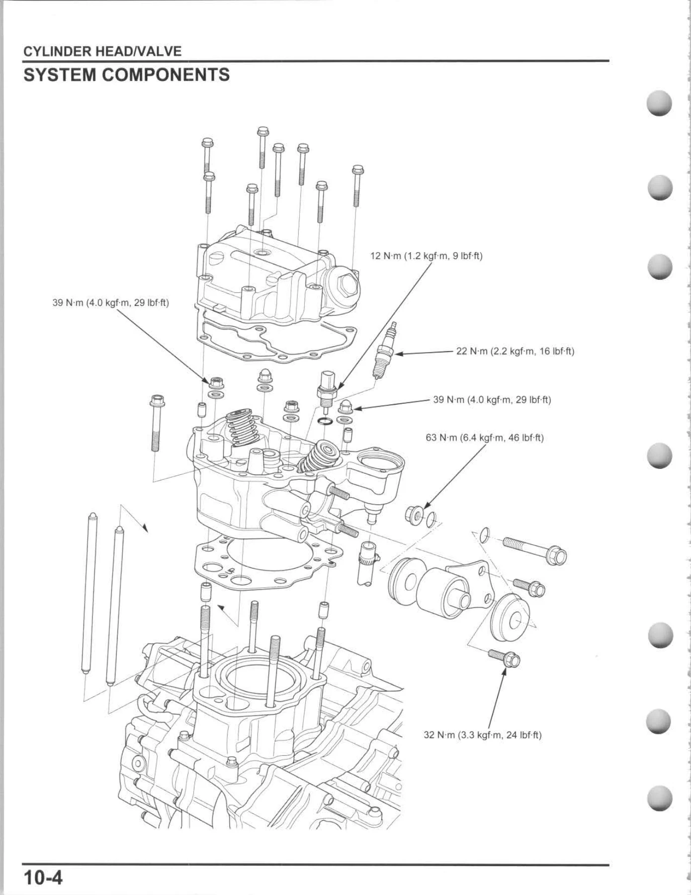
- 10. Cylinder Head/Valve — cylinder compression, cylinder head cover, cylinder head, camshaft
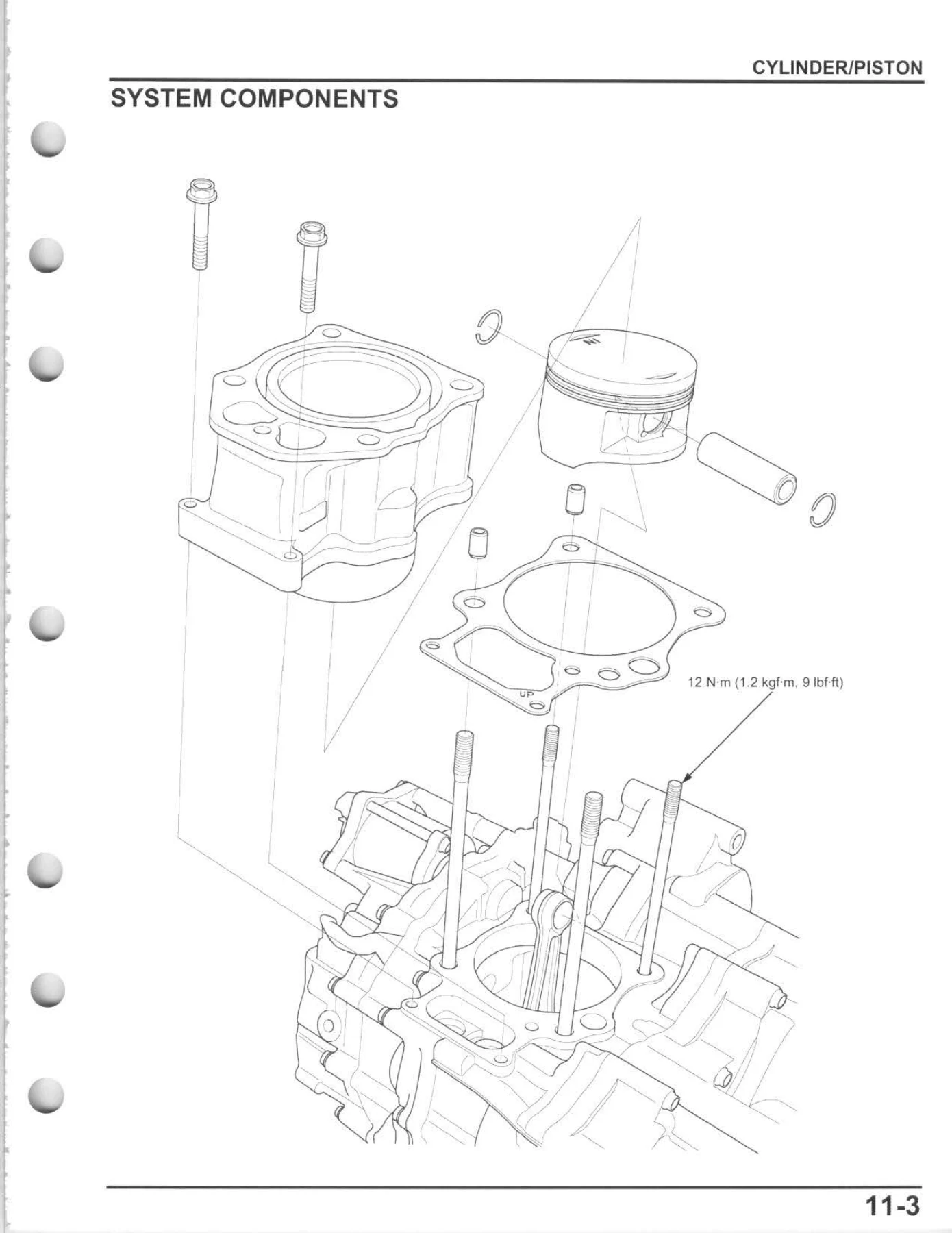
- 11. Cylinder/Piston — removal, inspection, piston ring installation, cylinder installation
- 12. Clutch/Gearshift Linkage (Except FA1/FA2 models) — front crankcase cover, centrifugal clutch, change clutch, gearshift linkage
- 13. Dual Clutch Transmission (FA1/FA2 models) — symptom troubleshooting, component location, system diagram, DTC index and troubleshooting, front crankcase cover/spacer, centrifugal clutch, shift solenoid valve, shift spindle angle sensor, shift control motor/reduction gears, shift drum position switch, reverse switch, EOT sensor, rear and front VS sensors, drive mode select switch, shift valve body, dual clutch/primary driven gear, gearshift linkage, reverse stopper shaft
- 14. Alternator/Starter Clutch — recoil starter (Canada models), alternator stator, flywheel/starter clutch
- 15. Crankcase/Transmission/Crankshaft/Balancer — crankcase separation and assembly, transmission, crankshaft/balancer, crankcase bearing replacement
- 16. Engine Removal/Installation
- 17. Front Wheel/Suspension/Steering — handlebar, throttle housing, front wheel, tires, wheel hub and knuckle, suspension arm, front shock absorber, steering shaft, steering shaft/EPS unit (FM2/FA2), tie-rod
- 18. Rear Wheel/Suspension — rear wheel, rear shock absorber, swingarm
- 19. Brake System — brake fluid replacement and air bleeding, brake pad/disc, front master cylinder, front brake caliper, rear brake drum/shoes, rear brake pedal
- 20. Front Driving Mechanism (Except TM1/TE1 models) — front drive shaft, front final drive removal, front propeller shaft, front final clutch, front final gear disassembly and inspection, gear case and cover bearing replacement, front final gear assembly, front final drive installation
- 21. Rear Driving Mechanism — rear axle removal and installation, rear final drive removal, rear final gear disassembly and inspection, gear case and cover bearing replacement, rear final gear assembly, rear final drive installation
- 22. Battery/Charging System — component location, system diagram, battery, charging system inspection, alternator charging coil, regulator/rectifier, main power relay
- 23. Lights/Meters/Switches — headlight, brake/taillight, combination meter/indicator, ignition switch, handlebar switch, gear position switch, front brake switch, rear brake light switch, cooling fan, fuel gauge/fuel indicator/fuel level sensor, 4WD select switch/4WD indicator
- 24. Electric Shift Program (ESP: TE1/FE1 models) — symptom troubleshooting, system diagram, troubleshooting information, DTC index and troubleshooting, VS sensor, shift spindle angle sensor, shift control motor/reduction gears
- 25. Electric Power Steering (EPS: FM2/FA2 models) — component location, system diagram, symptom troubleshooting, troubleshooting information, DTC index and troubleshooting, EPS indicator circuit inspection, EPS ECU
- 26. Wiring Diagrams — full wiring diagrams for TM1, TE1, FM1, FM2, FE1, FA1 and FA2 models
Across these 26 chapters, the manual documents the complete service life of a Rancher 420: routine maintenance intervals and procedures, engine top-end and bottom-end work, fuel injection diagnostics, cooling and lubrication systems, clutch and transmission service, front and rear driving mechanisms, brake and suspension overhauls, and full electrical troubleshooting with model-specific wiring diagrams.
Engine and Drivetrain Specifications You Will Find
The manual opens with a detailed specifications chapter covering the single-cylinder, longitudinally installed 420 cm³ engine — 86.5 x 71.5 mm bore and stroke, 9.9:1 compression ratio, liquid cooling, and PGM-FI fuel delivery through a 34 mm throttle bore. Torque values for standard fasteners and every major assembly are listed in dedicated tables, along with valve clearances, oil capacities, coolant capacities, final gear oil volumes, brake specifications, suspension settings and electrical service limits. Whether you need the cylinder head bolt torque sequence, the valve clearance for a routine adjustment, or the oil pressure specification for a dual-clutch FA-series machine, the numbers are all in one place.
Who This Manual Is For
This 2014 Honda Rancher TRX420 service repair manual is written for the technician or mechanically capable owner who wants to perform work to Honda’s published standards. It is not a simplified owner’s handbook or a generic ATV repair guide. Procedures are presented with step-by-step instructions, exploded illustrations, cross-references to the relevant specification tables, and clearly marked torque values. If you are rebuilding a top end, chasing a PGM-FI diagnostic trouble code, replacing a clutch, servicing a front final drive, or simply performing a valve clearance adjustment, the manual provides the sequence and the numbers.
Why the Correct Procedures and Specifications Matter
ATV drivetrains and fuel injection systems are unforgiving of guesswork. An incorrectly torqued cylinder head, a misadjusted valve clearance, a clutch assembled with the wrong clearance, or a PGM-FI fault diagnosed by parts-swapping can all lead to repeat failures, damaged components, or unsafe operation. This manual gives you the actual service limits, the correct assembly order and the diagnostic logic that Honda technicians use, so the job is done right the first time. For the FA1 and FA2 dual-clutch models, the manual includes the full DCT diagnostic and hydraulic circuit troubleshooting that is essential to keeping the automatic transmission shifting correctly.
IMAGES PREVIEW
Instant PDF Delivery
The 2014 Honda Rancher TRX420 Service Repair Manual is delivered as an instant PDF download — no shipping, no waiting, no physical book to store. Once your order is complete you can download the file immediately and open it on any device: laptop, tablet, smartphone or desktop computer. Print the pages you need for the workshop, or keep the full 566-page manual on your device for quick reference while you work. With coverage of all seven TRX420 models in a single document, this is the most complete service reference available for the 2014 Rancher 420.


Reviews
There are no reviews yet.