
2018 Sea-Doo GTI, GTR, GTS and Wake 155 Shop Service Manual
Original price was: $39.95.$24.95Current price is: $24.95.
Comprehensive factory shop service manual for 2018 Sea-Doo GTI, GTR, GTS, and Wake 155 personal watercraft. Covers Rotax 900 ACE, 1503 NA, 1503, and 1500 HO ACE engines with full disassembly, engine alignment, fuel injection, lubrication, closed-loop cooling, and electrical troubleshooting procedures.
Description
Complete Factory Workshop Coverage: 2018 Sea-Doo GTI, GTR, GTS and Wake 155 Shop Service Manual
This technical publication provides exhaustive maintenance, overhaul, and repair instructions for personal watercraft technicians and owners servicing 2018 BRP watercraft. Built around clear technical diagrams, precision torque values, and detailed assembly sequences, the 2018 Sea-Doo GTI, GTR, GTS and Wake 155 Shop Service Manual covers critical powertrain configurations including the Rotax 900 ACE / 900 HO ACE, Rotax 1503 NA / 1503 naturally aspirated engines, Rotax 1500 HO ACE supercharged units, and related Rotax high-output platforms. Whether performing routine seasonal maintenance, rebuilding a jet pump, aligning an engine to prevent driveline vibration, or diagnosing electronic fuel injection sensors, this manual provides the exact factory specifications required for reliable service.
Document Details
- Manual Type: Factory Shop Service Manual
- Brand: Sea-Doo / BRP (Bombardier Recreational Products)
- Covered Models: Sea-Doo GTI, Sea-Doo GTR, Sea-Doo GTS, and Sea-Doo Wake 155
- Engine Coverage: Rotax 900 ACE / 900 HO ACE (3-cylinder, 4-stroke), Rotax 1503 NA / 1503 (130 hp & 155 hp), Rotax 1500 HO ACE (230 hp supercharged), and Rotax 1630 ACE (300 hp)
- Document Numbers: 219100941 Series (including 219100941-005, 219100941-007, 219100941-008, 219100941-009, 219100941-037, 219100941-12, smr2017-003, smr2017-305, smr2017-307, smr2017-310, RTX1503ACEMY18, R900ACE)
- Language: English
- Page Count: 708 pages
- File Format: PDF (Immediate Digital Download)
System Overviews and Mechanical Procedures
The manual provides thorough coverage of mechanical, hydraulic, and electrical systems designed specifically for Sea-Doo watercraft architectures. Every subsection emphasizes proper tool utilization, component cleanliness, and strict adherence to fastener tightening torques.
Engine Removal, Installation, and Driveline Alignment
Detailed step-by-step procedures guide technicians through removing and reinstalling engines without risking hull, electrical harness, or cooling fitting damage. Comprehensive alignment guides ensure proper coupling between the crankshaft PTO coupler and the jet pump driveshaft:
- Rotax 900 ACE Powertrains: Step-by-step hoisting, motor mount clamp removal, and precision alignment utilizing the Pump Plate (P/N 529 036 224), Alignment Shaft Support (P/N 529 035 506), Alignment Shaft (P/N 295 000 141), and PTO Adapter (P/N 529 036 273), including verification of longitudinal marks at 598 mm and 600 mm.
- Rotax 130, 155, 230, and 300 Powertrains: Dedicated mounting bracket diagrams for the Wake 155 and other models, shim adjustment limits (maximum 5 mm / 13/64 in), and driveshaft alignment verification using Alignment Shaft Adapter (P/N 529 035 719) with longitudinal tolerance lines scribed at 739.5 mm and 742.5 mm.
- Mounting Hardware Integrity: Precise torque specifications for engine mount clamp nuts (26 N•m ± 2 N•m / 19 lbf•ft) and base retaining fasteners, ensuring conical spring washers are oriented with ‘T’ marks facing upward.
Intake, Supercharging, and Exhaust Systems
Proper airflow and thermal management are vital for performance and compliance with marine emissions regulations. The 2018 Sea-Doo GTI, GTR, GTS and Wake 155 Shop Service Manual details complete intake and exhaust servicing:
- Air Intake Assemblies: Removal, disassembly, and servicing of upper and lower intake silencers, baffle indexing, connecting sockets, and flame arresters. Includes intake manifold torque sequences (9 N•m ± 1 N•m) and Oetiker clamp crimping dimensions (2.2 mm ± 1 mm).
- Exhaust System Mechanics: Total Loss Cooling System (TLCS) routing, calibrated outlet fittings, freshwater flushing protocols, muffler repositioning, resonator removal, and exhaust manifold multi-step tightening sequences.
- Intercooler and Supercharger Care: Intercooler draining procedures to expel condensation on 230 hp and 300 hp models, supercharger slip-clutch inspection, and specialized oil spray nozzle checks.
Lubrication and Closed-Loop Cooling Systems
Watercraft engines operate in punishing marine environments requiring reliable oil flow and internal corrosion prevention. Detailed technical illustrations explain:
IMAGES PREVIEW
- Dry Sump Lubrication: Dual suction pump module overhaul, oil pressure pump tolerances (radial clearance limit 0.25 mm, axial clearance limit 0.15 mm), oil pressure regulator spring limits (outer spring service limit 57 mm on 1503; 45 mm on 900 ACE), and oil pressure switch (OPS) resistance testing.
- Engine Oil and Filter Service: Oil level verification procedures, siphon evacuation methods using Suction Pump (P/N 529 035 880) at specified depth intervals, and XPS 4-Stroke Synthetic Blend recommendations.
- Closed Loop Cooling System (CLCS): Cylinder block and cylinder head coolant circulation, ride plate heat exchanger draining, cooling system pressure testing at 110 kPa (16 PSI), thermostat opening inspection (starts opening at 80°C / 176°F), and water pump rotary and oil seal replacement using specialized seal pushers.
- Tip-Over Protection (TOPS): Hall-effect sensor operation, electrical continuity, and voltage testing (0.4 Vdc normal to 4.4 Vdc inverted) to protect engines during capsizing.
Magneto, Charging, and Starting Systems
Complete diagnostic procedures allow technicians to isolate starting and electrical faults quickly:
- Stator Electrical Checks: Resistance testing across yellow wire terminals (0.1 to 1.0 Ω at 20°C), insulation-to-ground resistance (infinity/open circuit), and AC idle output voltage verification (±25 Vac).
- Flywheel, Sprag Clutch, and Starter Drive: Rotor extraction with Flywheel Puller (P/N 420 976 235) and Crankshaft Protector (P/N 529 036 213), sprag clutch directional locking inspection, starter drive bendix servicing, and starter motor direct voltage drop testing.
Chapters Covered
- SAFETY NOTICE & GENERAL INTRODUCTION
- Safety Guidelines, Special Service Tools, and Fastener Standards
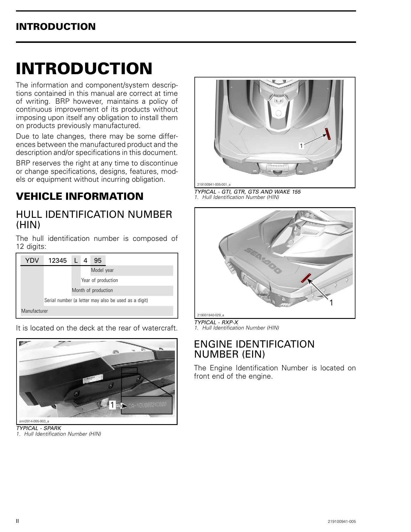
- Hull Identification Number (HIN) and Engine Identification Number (EIN) Locations
- Watercraft Hoisting and Stand Mounting with Lifting Strap (P/N 529 036 189)
- EPA Emissions Certification, Responsibilities, and Fuel Requirements
- Manual Layout, Metric Fasteners, and Crisscross Tightening Principles
- Self-Locking Fastener and Loctite Application Procedures (Blind Holes, Studs, Shafts)
- Stripped Thread Repair with Form-A-Thread Compounds
- PERIODIC MAINTENANCE & PRESEASON PREPARATION
- Maintenance Schedule: Pre-Ride, Post-Operation, 100-Hour / 1-Year, 200-Hour / 2-Year, 300-Hour / 5-Year Intervals
- Storage and Winterization Procedures: Propulsion Flushing, Fuel Stabilization, Intercooler Draining
- Engine Compartment Cleaning, Bilge Drainage, and Internal Cylinder Fogging
- Preseason Preparation and Four-Month Inactivity Procedures
- SPECIAL PROCEDURES
- Safe Watercraft Towing Procedures in Water (Maximum 24 km/h / 15 MPH)
- Submerged Watercraft Recovery and Immediate Decontamination
- Water-Flooded Engine De-Watering, Intake Siphoning, and Oil Evacuation
- Test Tank / Trailer Boil-Out Procedure with BUDS2 Coolant Temperature Monitoring
- ENGINE REMOVAL, INSTALLATION & ALIGNMENT
- Rotax 900 ACE Engine Removal, Disconnection Points, and Lifting Fixtures
- Rotax 900 ACE Driveline Alignment, Shimming, and Longitudinal Distance Verification
- Rotax 130, 155, 230, and 300 Engine Removal Guidelines and Disconnection Checklist
- Wake 155 and Multi-Model Engine Support Brackets and Mount Torquing
- Rotax 1503 / 1630 Driveline Alignment Tooling, Adapter Scribing, and Shimming
- AIR INTAKE SYSTEM
- Rotax 900 ACE Intake Manifold, MAPTS, and Fuel Rail Disassembly
- Flame Arrestor Extraction, Cleaning, and Oetiker Clamp Crimping Specifications
- Air Intake Silencer Disassembly, Internal Baffle Alignment, and Torx Fastening
- Rotax 130, 155, 230, and 260 Air Intake Silencer Removal, Ducting, and Partition Access
- Supercharged Model Air Intake Tube Removal and Installation
- EXHAUST SYSTEM
- Total Loss Cooling System (TLCS) Operation and Calibrated Fittings
- Exhaust System Freshwater Flushing Procedures and Flush Adapter (P/N 295 500 473)
- Muffler Removal, Inspection, Engagement Length Scribing, and Adjuster Block Setup
- Exhaust Manifold Removal, Injection Hole Cleaning, and Tightening Sequences
- Resonator Removal, Exhaust Hose Clamp Torques, and P80 Grip-It Lubricant Application
- LUBRICATION SYSTEM (ROTAX 900 ACE)
- Dry Sump System Description and Dual Suction Pump Mechanics
- Engine Oil Pressure Testing at Specified RPM Ranges and Test Plug Installation
- Low Oil Pressure, High Oil Consumption, and Milky Contamination Troubleshooting
- Oil Pressure Switch (OPS) Resistance, Activation Ranges, and Continuity Checks
- Oil Filler Tube, Oil Tank Cover, and Oil Cooler Removal and Multi-Step Torquing
- Oil Pressure Regulator Inspection, Spring Free Length Measurement, and Piston Bore Check
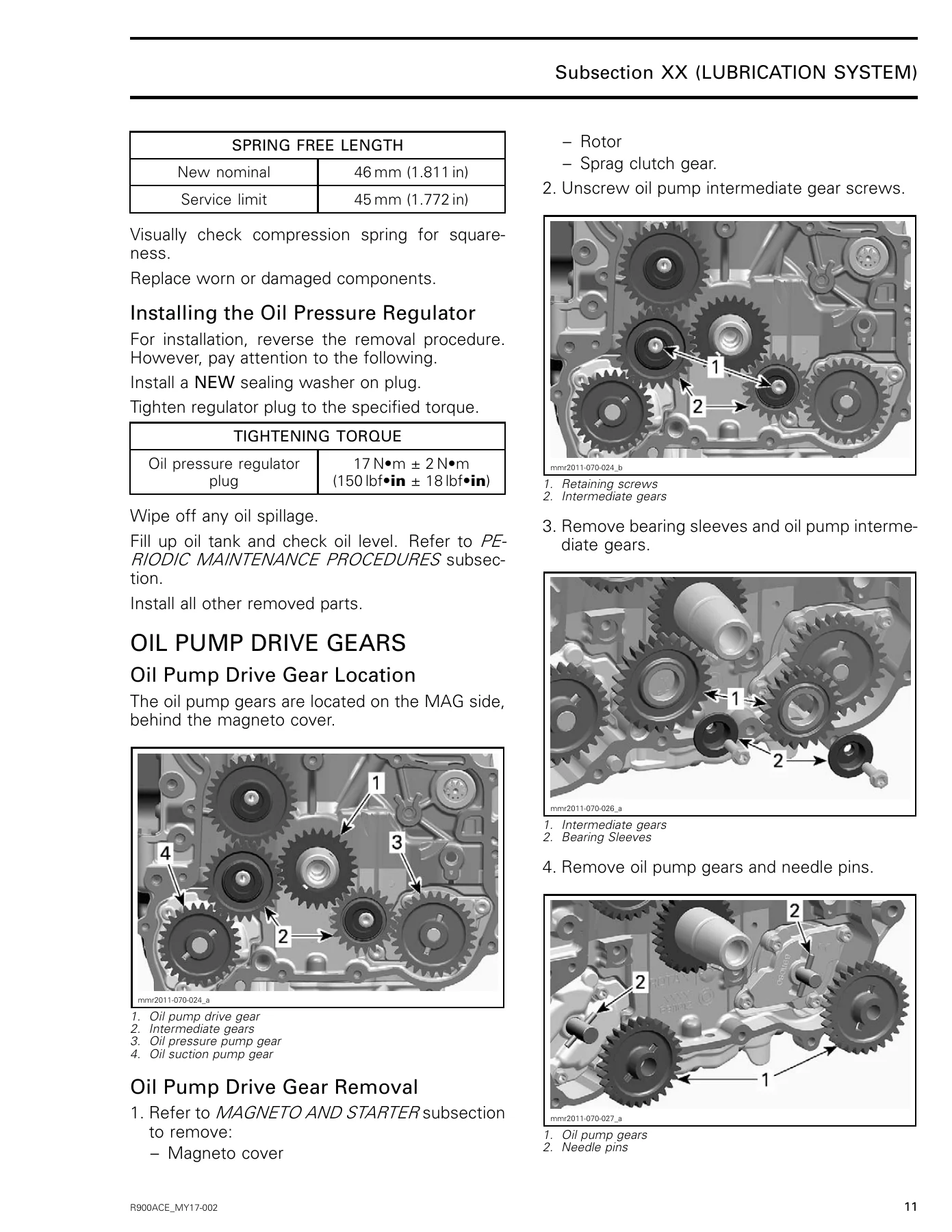
- Oil Pump Drive Gears, Oil Pressure Pump, and Oil Suction Pump Module Rebuild
- Oil Sump Cover Removal, Internal Strainer Cleaning, and Reinstallation Sequence
- LUBRICATION SYSTEM (ROTAX 1503 / 1630 ACE & 130/155/230/300)
- Lubrication Circuit Routing: Pressurized Paths, Scavenge Flow, and Blow-By Return
- Recommended Oils, XPS Synthetic Blend Requirements, and Wet Clutch Compatibility
- Accurate Dipstick Oil Level Verification and Siphon Evacuation Procedure
- Oil Filter Replacement, Cover O-Ring Lubrication, and Housing Bore Cleaning
- Oil Pressure Switch (OPS) and Oil Temperature Sensor (OTS) Resistance Testing
- PTO Oil Strainer Removal, Cleaning, and Multi-Purpose Grease Positioning
- Oil Pressure Regulator Removal, Guide Inspection, and Spring Free Length Limits
- Oil Pressure Pump Disassembly, Rotor Clearance Measurement, and Rotary Seal Replacement
- Rotary Seal Removal with Ceramic Seal Puller (P/N 529 036 365) and Press-Fit Installation
- Oil Suction Pump Removal, Gear Inspection, and Cover Tightening Sequence
- Supercharger Oil Spray Nozzle Inspection and Piston Oil Spray Nozzle Replacement
- Oil Separator Cover Removal, Holding Clip Safety, and Thrust Washer Handling
- Blow-By Valve Operation, Gravity-Assisted Valve Piston, and Air Flow Testing
- Tip-Over Protection Switch (TOPS) Operation, Inverted Voltage Testing, and Replacement
- COOLING SYSTEM – ENGINE (ROTAX 900 ACE)
- Closed Loop System Circuitry, Cylinder Block Flow, and Cylinder Head Bleed Fitting
- Cooling System Leak Testing with Test Cap (P/N 529 035 991) at 110 kPa (16 PSI)
- Engine Overheating Troubleshooting Chart and Leak Indicator Hole Inspection
- Thermostat Housing Removal, Bench Testing Temperatures, and Dow Corning 111 Sealing
- Water Pump Housing Removal, Impeller Removal, and Shaft Extraction
- Water Pump Drive Gear, Bearing Sleeve, and Rotary Seal Rebuild with Seal Pushers
- COOLING SYSTEM – ENGINE (ROTAX 1503 / 130/155/230)
- Closed Loop Engine Cooling Flow and Thermostat Operation (Opens at 80°C / 176°F)
- Cooling System Leak Test Procedures at 90 kPa (13 PSI) with Vacuum/Pressure Pump
- Water Pump Housing Removal, Reverse Left-Hand Thread Impeller Inspection, and Sealing
- Water Pump Impeller Torquing (3 N•m ± 0.4 N•m / 27 lbf•in) and Shaft Inspection
- COOLING SYSTEM – VEHICLE
- Ride Plate Heat Exchanger Function, Coolant Draining, and System Chemical Cleaning
- Refilling Procedure, Bleeding Cycles, and Loctite 567 Pipe Sealant Application
- Coolant Reservoir Pressure Cap Testing (110 kPa ± 7 kPa / 16 PSI)
- Closed Loop and Open Loop Intercooler/Exhaust Cooling Schematics for Rotax ACE Platforms
- MAGNETO AND STARTER (ROTAX 900 ACE)
- Magneto Cover Removal, Gasket Cleaning, and Stator Cable Routing Safety
- Stator Resistance, Ground Insulation, and AC Output Voltage Verification
- Flywheel Rotor Removal with Crankshaft Protector and Puller Fixtures
- Sprag Clutch Removal, Directional Rotation Verification, and Loctite 648 Assembly
- Starter Drive Double Gear Inspection and Starter Motor In-Vehicle Voltage Drop Testing
- PTO HOUSING, MAGNETO AND STARTER (ROTAX 1503 / 1630 ACE)
- PTO Housing Disassembly, Gasket Replacement, and Stator Harness Sealing (Loctite 5910)
- PTO Seal Inspection, Ball Bearing Play, and Oetiker Clamp Positioning
- PTO Coupling Removal with Impeller Tool (P/N 529 035 820) and Stop Sleeve Setup
- Stator Testing, Output Verification, and Correct Stator Notch Orientation
- Flywheel Rotor and Trigger Wheel Inspection, Dial Indicator Runout Measurement
- Trigger Wheel Location Pin Indexing and Rotor Stretch Screw Torque-Angle Procedure
- Starter Drive Sprag Clutch Overhaul, Needle Bearing Replacement, and Thrust Washers
- Starter Motor Removal, O-Ring Lubrication with Triple-Guard Grease, and Solenoid Bypass Testing
- INTAKE MANIFOLD & FUEL INJECTION (ROTAX 130, 155, 230)
- Intake Manifold Removal on 130/155 and 230 Models, Harness Disconnection, and ECM Detachment
- Fuel Rail and Fuel Injector Connector Handling, Dipstick Clearance, and Gasket Replacement
- Intake Manifold Multi-Bolt Tightening Sequence (11 N•m ± 1 N•m) and ECM Bracket Torquing
- Integrated Flame Arrester Inspection and Maintenance Guidelines
- TIMING CHAIN & VALVETRAIN (ROTAX 900 ACE)
- Hydraulic Timing Chain Tensioner Removal, Plunger Check, and Sealing Washer Replacement
- Camshaft Timing Gears Removal, Inspection, and Vice-Clamping Safeguards
- Timing Chain Removal, Crankshaft Lifting, Thrust Washer Inspection, and Wear Limits
- Lower Timing Chain Guide and Tensioner-Side Chain Guide Inspection (1 mm Maximum Groove Depth)
- Cylinder Leak-Down Testing Protocols (0–15% Excellent to 41%+ Poor Condition Diagnosis)
- Valve Cover Removal, Spark Plug Tube Gaskets, and V-Ring Alignment Procedures
Together, these chapters provide technicians with complete factory diagnostic parameters, step-by-step disassembly guidelines, detailed component wear limits, and exact reassembly sequences. From minor seasonal preparation to full powertrain overhauls, every mechanical operation is thoroughly supported.
Professional Capability, Factory Precision, and Instant Digital Delivery
Working on modern high-performance personal watercraft demands strict adherence to factory procedures. Guessing motor mount alignment angles can cause premature wear ring destruction, driveshaft spline failure, or carbon ring leakage. Similarly, improper torquing of flywheel stretch screws, incorrect oil pump rotor clearances, or improper cooling system bleeding can lead to severe engine failure. The 2018 Sea-Doo GTI, GTR, GTS and Wake 155 Shop Service Manual delivers the exact engineering specifications, clearance thresholds, and diagnostic testing methods developed by BRP engineers.
Delivered as an immediate PDF download upon purchase, this manual provides instant access on your computer, tablet, or smartphone without waiting for printed delivery. Cleanly indexed and fully viewable in the workshop, on the trailer ramp, or at the dock, individual pages or entire sections can be printed on demand to keep greasy hands away from your digital screen. Equip your workshop with the definitive factory repair manual for the 2018 Sea-Doo GTI, GTR, GTS and Wake 155 today.
Reviews
There are no reviews yet.