★ TRUSTED BY 321,897+ PROFESSIONALS WORLDWIDE
🏒
Trusted Business
Verified & Licensed
πŸ›‘οΈ
Virus Free Files
100% Safe Downloads
πŸ”’
Secure Payment
SSL Protected
⚑
Instant Delivery
Available Immediately
Sale!

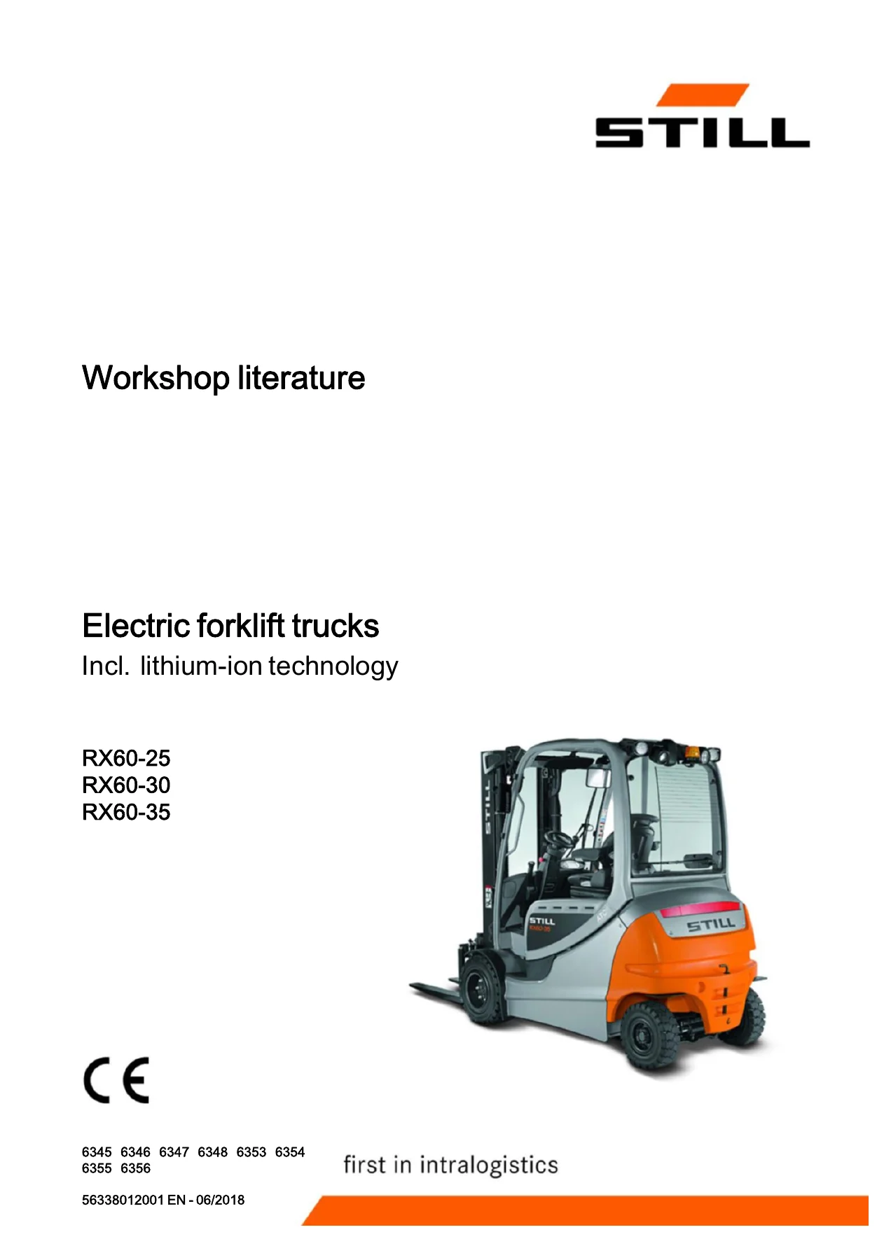
2018 STILL RX60-25 RX60-30 RX60-35 Electric Forklift Workshop Manual – PDF Download

Original price was: $39.95.Current price is: $23.95.

Complete 416-page STILL workshop literature for the RX60-25, RX60-30 and RX60-35 electric forklift trucks (Edition 2018/06, Version 2, doc 56338012001 EN). Covers drive axle, hydraulics, electrics, MaLiS lift masts, lithium-ion battery and DiaMon/STEDS diagnostics.

⚑
Instant PDF Download
Available immediately
πŸ’Ύ
Save to Your Device
Download & keep forever
πŸ›‘οΈ
Antivirus Scanned
100% virus-free
🌍
Trusted Worldwide
175,000+ customers

Description

2018 STILL RX60-25, RX60-30 and RX60-35 Electric Forklift Workshop Manual

This is the full STILL workshop literature for the RX60-25, RX60-30 and RX60-35 series electric forklift trucks, published as document 56338012001 EN in June 2018 under Edition 2018/06, Version 2. Across 416 pages it covers the complete truck, from the traction motor and Carraro EC35 drive axle to the hydraulic system, MaLiS lift masts, electrical and electronic controls, brake systems, lithium-ion battery technology and the DiaMon / STEDS-Navigator diagnostic environment. This is the same reference material a STILL service engineer works from β€” not a generic overview.

File Details

  • Manual type: Workshop literature / service and repair manual
  • Brand: STILL
  • Model series: RX60-25, RX60-30, RX60-35 electric forklift trucks
  • Type carriers covered: 6345, 6346, 6347, 6348, 6353, 6354, 6355, 6356
  • Document number: 56338012001 EN
  • Edition: 2018/06 β€” Version 2
  • Language: English
  • Pages: 416
  • Format: PDF

Chapters Covered

  • 00 Product information β€” Foreword, product overview for the RX60 25-35, safety information, parking the truck secured for service work, working on the electrical system, jacking up the front and rear, securing the fork carriage, restrictions and obligations, penalties, speed limitation with a Tensor battery and for legal use on public roads
  • 01 Service β€” Maintenance 1000 hours/annually, maintenance 3000 hours/every two years, operating materials, measuring instruments and testing equipment, harnesses and hoists 1.0 t – 3.5 t, standardised tightening torques for standard-pitch, fine-pitch threads and hose fittings
  • 02 Diagnostics β€” Introduction to DiaMon, STEDS-Navigator, diagnostics service box, diagnostic set-up, starting DiaMon, working with DiaMon, reading out and clearing the error list, reading out access codes, working using ABE, clearing error lists
  • 11 Electric motor β€” Traction motor general technical data, electrical connections, traction drive, sensors, pin sensor, temperature sensor KTY84
  • 22 Mechanical drive axle β€” Drive axle EC35 general technical data Carraro EC 35, drive axle without pump motor removal and installation, drive axle with pump motor removal and installation, wheel drive, service brake, differential gearbox and brake, basic setting of the brake system, testing the brake system
  • 30 Chassis, bodywork and fittings β€” Frame, working with gas springs, battery door, battery lock, battery door sensor, counterweight
  • 42 Steering system β€” Hydraulic steering general technical data, steering unit, steering wheel and steering column, steering angle sensor 3B01, steering angle-dependent handling performance CSC, CSC functional test, steering axle, swing axle, wheel hub, steering angle, tie rod, axle stub
  • 50 Operating devices β€” Drive and brake actuation, changing the brake cable for the service brake, brake cable change for handbrake, actuating force of the handbrake, brake sensor, parking brake switch 1S3, accelerator pedal generation 2, accelerator single-pedal, electric parking brake
  • 56 Operating console β€” Turn indicator module for the drive direction generation 2, direction indicator module FABLI, display and operating unit ABE 2
  • 60 Electrics/electronics β€” General technical data, overview of controllers, electrical system, switch-on process, software compatibility, PAN process, parameter management, error ring buffer, temperature monitoring, electrical checks, intermediate circuit, insulation testing, CAN bus system, power cables, fuses, contactor, sensor system, vertical lift mast position, tilt angle sensor 7B46, load measurement, additional electrical installation, 7A21 converter PCB, Option Board, CAN-Power-Port (CPP), Relay-Power-Port (RPP)
  • 64 Electronic controls β€” Truck control unit, Main Control Unit (MCU 2), MCU removal and installation, Supply Unit (SU 2), SU removal and installation, converters, inverters
  • 69 Batteries and accessories β€” Lead-acid battery, 2014 discharge indicator, battery plug, maintenance guidelines for appliance plugs, repair of battery male connector contacts, working with reducer sleeves, lithium-ion technology, working on lithium-ion batteries, general technical data, battery management system (BMS), diagnostics, battery display, battery discharge indicator, battery charge, battery male connector, battery discharge, deeply discharged battery, removing/installing the battery cable, converting from lead-acid to lithium-ion
  • 70 Hydraulics β€” General β€” General technical data, hydraulic oil, depressurising the hydraulics, lifting, lowering and tilting operating speeds, safety check, basic hydraulics, hydraulic tank, return line filter, breather filter, intake filter, high-pressure filter, conical nipple fittings, bolted joint
  • 71 Working hydraulics β€” Pump-motor unit, tilt cylinder, mast tilt, auxiliary hydraulics, attachments, second operating function for attachments, clamp locking mechanism with servo hydraulics, clamp locking mechanism for hand levers, accumulator
  • 76 Valves β€” Hand lever general technical data, hand lever valve block, emergency lowering, hydraulic transmitter, valve block removal/installation, directional control valve block, check valve for hydraulics blocking function, servo hydraulics valve block, manual lowering, directional control valve block (servo)
  • 80 Load lift system β€” Mast bearings, Carraro MaLiS mast bearing
  • 81 MaLiS lift mast β€” Lift mast general technical data, hose safety valve of triplex mast, support roller play (108/117/130), load chains checking and cleaning, run-out barrier, working on lift masts, lift mast removal and installation, telescopic lift mast, NiHo lift mast, triplex lift mast, lift cylinder, outer cylinders, middle cylinder, end position damping
  • 84 Load support β€” Fork carriage removal and installation, fork wear protection
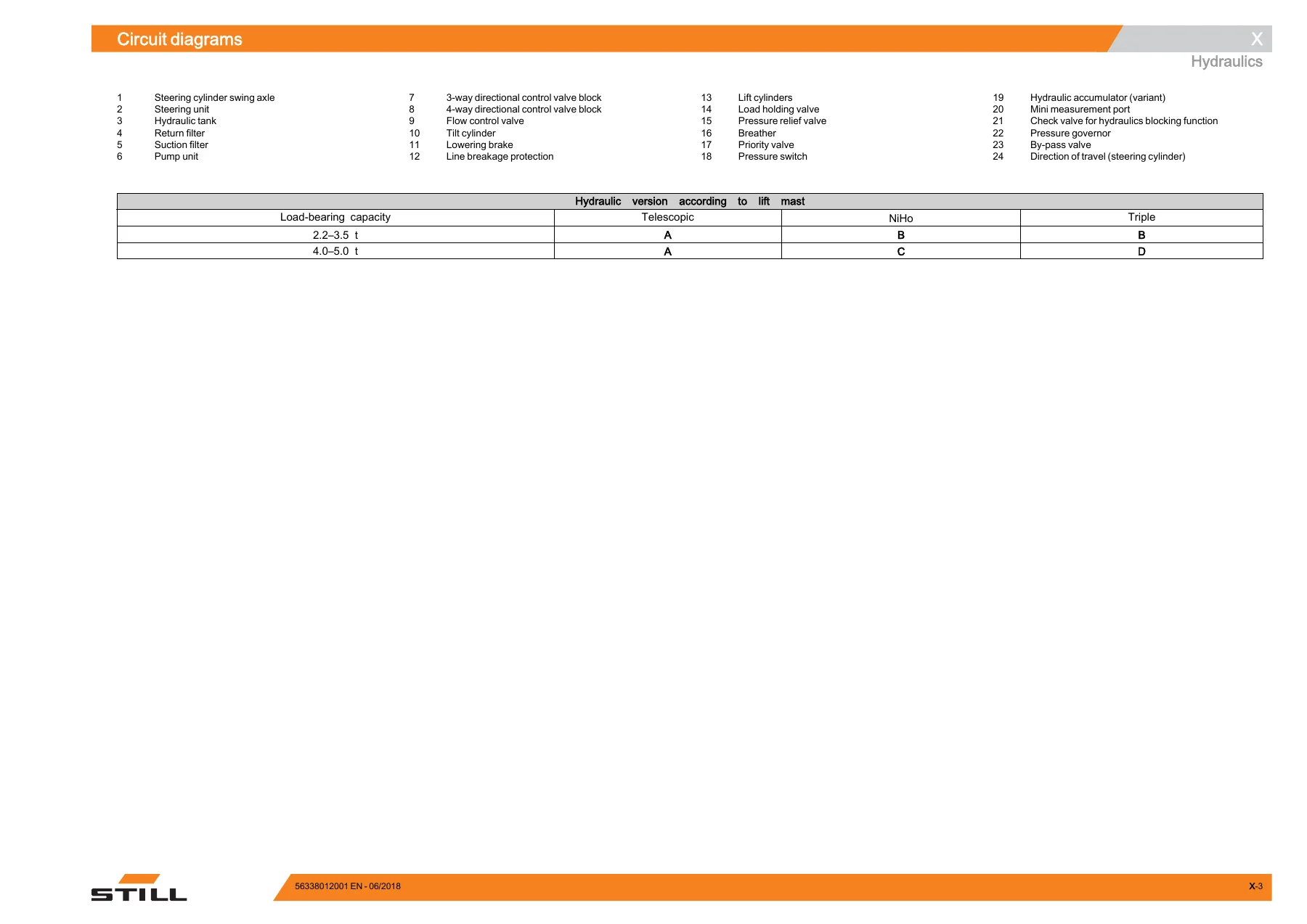
  • X Circuit diagrams β€” Hydraulic circuit diagram multi-levers, hydraulic circuit diagram servo hydraulics

Together these chapters give a technician the full picture of the RX60-25 / RX60-30 / RX60-35 truck: how each assembly is built, how it comes apart, what the correct torque, clearance and adjustment values are, and how the truck’s controllers and CAN bus networks interact. The mix of mechanical procedures (drive axle, wheel hubs, lift cylinders, mast rollers) with electrical and diagnostic content (insulation testing, converter replacement, parameter copying, error ring buffer) means this is a single reference for the whole machine rather than a parts-only or electrical-only book.

What This Manual Helps You Do

Whether you are servicing a single RX60-25 or maintaining a fleet of RX60-30 and RX60-35 trucks, this STILL RX60-25/30/35 electric forklift workshop manual covers the tasks you would otherwise have to guess at: removing and refitting the Carraro EC35 drive axle with or without the pump motor, setting the multi-disc brake on the differential gearbox, adjusting the load chains and support roller play on MaLiS telescopic, NiHo and triplex lift masts, changing the electric parking brake cable and running its calibration, diagnosing the truck with DiaMon and STEDS-Navigator, reading and clearing the error list, and interpreting the intermediate circuit, insulation and CAN bus tests.

Complete PDF Bookmark Tree

Complete Bookmarks

The complete bookmarks in the β€œ2018 STILL RX60-25 RX60-30 RX60-35 Electric Forklift Workshop Manual – PDF Download” are as follows:

56338012001p. 1
History of changesp. 3
Headerp. 5
Information about the documentationp. 5
Specialistp. 5
Symbols Usedp. 6
Changes and retrofittingp. 6
Working with spare partsp. 7
Table of contentsp. 9
00 Product informationp. 19
Forewordp. 19
Product overview for the RX60 25-35p. 19
Safety informationp. 21
Parking the truck so it is secured for service workp. 21
Working on the electrical systemp. 22
Jacking up the front of the truckp. 22
Jacking up the rear of the truckp. 23
Securing the fork carriagep. 25
Restrictions and obligationsp. 27
Penaltiesp. 27
Speed limitation with a Tensor batteryp. 27
Speed limitation for legal use on public roadsp. 27
01 Servicep. 29
Maintenancep. 29
Maintenance instructionsp. 29
Maintenance β€” 1000 hours/annuallyp. 31
Maintenance – 3000 hours/every two yearsp. 33
Operating materialsp. 34
Measuring instruments and testing equipmentp. 34
Harnesses and hoists, 1.0 t – 3.5 tp. 36
Standardised tightening torques for standard-pitch threads and fine-pitch threadsp. 37
Standardised tightening torques for hose fittingsp. 38
02 Diagnosticsp. 39
Introduction to DiaMonp. 39
STEDS-Navigatorp. 39
Diagnostics service boxp. 40
Diagnostic set-upp. 41
Starting DiaMonp. 42
Working with DiaMonp. 43
Reading out and clearing the error listp. 43
Reading out access codesp. 44
Working using ABEp. 45
Read error listp. 45
Clearing error listsp. 47
11 Electric motorp. 49
Traction motorp. 49
General technical datap. 49
Electrical connectionsp. 49
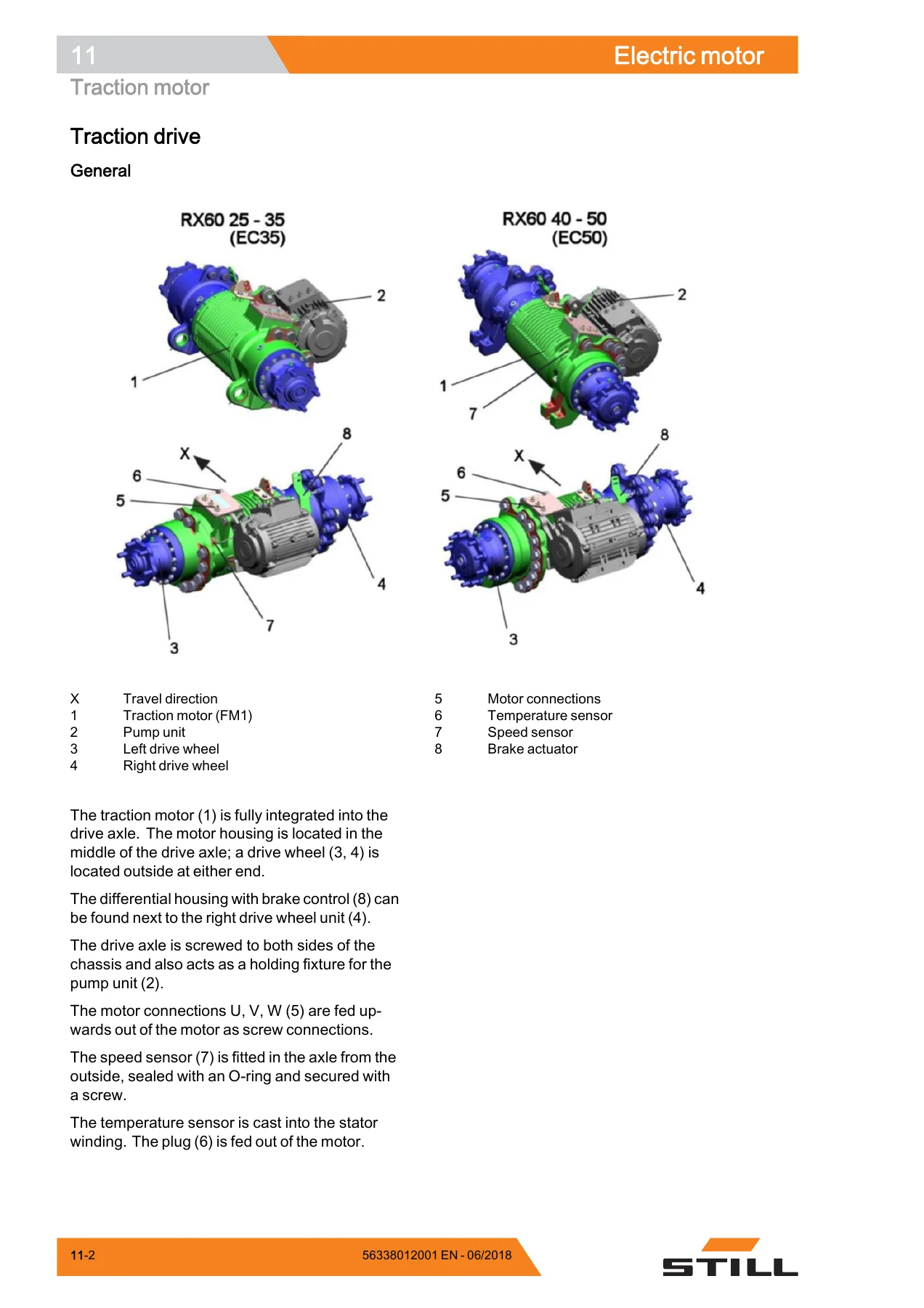
Traction drivep. 50
Traction motorp. 52
Sensorsp. 54
Pin sensorp. 54
Temperature sensor KTY84p. 55
22 Mechanical drive axlep. 59
Drive axle EC35p. 59
General technical data Carraro EC 35p. 59
Drive axlep. 61
Drive axle without pump motor Removal and installationp. 62
Drive axle with pump motor Removal and installationp. 65
Wheel drivep. 69
Service brakep. 73
Removing/installing the service brakep. 73
Differential gearbox and brakep. 75
Removal of the differential gearbox and brakep. 77
Installation of the differential gearbox and brakep. 80
Basic setting of the brake systemp. 83
Testing the brake systemp. 87
30 Chassis, bodywork and fittingsp. 89
Framep. 89
Working with gas springsp. 89
Battery doorp. 90
Battery lockp. 91
Battery door sensorp. 93
Counterweightp. 94
Counterweightp. 94
42 Steering systemp. 95
Hydraulic steeringp. 95
General technical datap. 95
Steering systemp. 96
Steering β€” error detectionp. 98
Steering unitp. 99
Priority valvep. 102
Steering wheel and steering columnp. 104
Steering columnp. 104
Steering angle sensor 3B01p. 106
Steering angle-dependent handling performance β€” CSCp. 108
CSC β€” functional testp. 109
Steering axlep. 113
General technical datap. 113
Swing axlep. 114
Swing axle curve switchp. 115
Removing/installing the swing axlep. 116
Wheel hubp. 118
Steering anglep. 121
Tie rodp. 122
Axle stubp. 123
50 Operating devicesp. 125
Drive and brake actuationp. 125
Brake actuationp. 125
Changing the brake cable for the service brakep. 125
Brake cable change, handbrakep. 127
Actuating force of the handbrakep. 129
Brake sensorp. 131
Parking brake switch 1S3p. 132
Accelerator pedal, generation 2p. 133
Accelerator β€” single-pedalp. 136
Electric parking brakep. 139
Functionp. 140
Cause and effectp. 142
Design and system descriptionp. 144
Maintenance instructionsp. 146
Checking the brakep. 147
Calibration and functional testp. 149
Changing the parking brake cablep. 152
Limit position switchp. 155
Drive unit Installation and removalp. 157
Central lubrication device Installation and removalp. 159
Dual pedalp. 162
Accelerator – dual pedal, generation 2p. 162
Operating devicesp. 166
Hand leverp. 166
Joystick 4Plusp. 168
Axle assignment – Joystick 4Plusp. 169
Generation 2 mini-leverp. 171
Axle assignment – the mini-leverp. 173
Tip switchp. 175
Axle assignment – fingertip switchp. 176
56 Display elementsp. 179
Operating consolep. 179
Turn indicator module for the drive direction, generation 2p. 179
Direction indicator module (Fabli)p. 180
Displayp. 183
Display and operating unit, generation 2 (ABE 2)p. 183
ABE 2 Installation and removalp. 184
60 Electrics/electronicsp. 187
Generalp. 187
General technical datap. 187
Overview of the controllersp. 188
Electrical systemp. 189
Electrical componentsp. 189
Switch-on process for the electrical systemp. 191
Software compatibilityp. 195
PAN processp. 196
Parameter managementp. 197
Error ring bufferp. 198
Temperature monitoring for the traction motor – 80 Vp. 200
Temperature monitoring for the traction motor converterp. 201
Pump motor temperature monitoringp. 202
Temperature monitoring for the pump motor converterp. 204
Available driving behaviourp. 205
Revolution-controlled vs. torque-regulatedp. 205
Blue-Q = IQp. 206
Starting current boostp. 207
Stopping on a slopep. 207
Electrical checksp. 209
Intermediate circuitp. 209
Insulation testing for electric trucksp. 210
Insulation testing on the drive batteryp. 212
Insulation testing the lithium-ion batteryp. 213
Component insulation testingp. 214
Wiringp. 217
CAN bus systemp. 217
CAN bus connectionsp. 219
Power cablesp. 221
Maintenance guidelines for power cablesp. 222
Repair – Contact elementsp. 222
Electrical systemp. 224
Fuse boxp. 224
Fusesp. 224
Contactorp. 225
Sensor systemp. 227
Vertical lift mast positionp. 227
Tilt angle sensor 7B46p. 228
Load measurementp. 231
Load measurement pressure sensorp. 233
Additional electrical installationp. 234
7A21 converter PCBp. 234
Option Boardp. 235
CAN-Power-Port (CPP)p. 237
CPP 1/CPP 3p. 237
CPP 2Bp. 239
CPP battery carrier (CPP5)p. 240
Relay-Power-Portp. 241
64 Electronic controlsp. 243
Truck control unitp. 243
Main Control Unit (MCU 2)p. 243
Main Control Unit (MCU) Removal and installationp. 244
Supply Unit (SU 2)p. 246
Supply Unit (SU) Removal and installationp. 247
Converterp. 250
Invertersp. 250
SAC converter β€” 80 Voltp. 250
Inverters Removal and installationp. 252
69 Batteries and accessoriesp. 255
Lead-acid batteryp. 255
Batteryp. 255
2014 discharge indicatorp. 257
Battery plugp. 260
Maintenance guidelines for appliance plugsp. 261
Repair – Battery male connector contactsp. 263
Working with reducer sleevesp. 265
Lithium-ion technologyp. 266
Working on lithium-ion batteriesp. 266
General technical datap. 267
Battery management system (BMS)p. 268
Diagnosticp. 269
Battery displayp. 270
Battery discharge indicator for a lithium-ion batteryp. 271
Battery chargep. 274
Battery male connectorp. 275
Battery dischargep. 276
Course of action for a deeply discharged batteryp. 278
Checking that the battery male connector is de-energisedp. 278
Removing/installing the battery cablep. 279
Converting from a lead-acid battery to a lithium-ion batteryp. 280
70 Hydraulicsp. 285
Generalp. 285
General technical datap. 285
Hydraulic oilp. 287
Depressurising the hydraulicsp. 288
Lifting operating speedsp. 290
Lowering operating speedsp. 291
Tilting operating speedsp. 291
Safety checkp. 293
Forward tilt safety testp. 293
Lowering safety testp. 293
Safety checks of hose assemblyp. 294
Basic hydraulicsp. 295
Steering hydraulicsp. 296
Working hydraulicsp. 297
Hydraulic tankp. 298
Hydraulic oilp. 299
Return line filterp. 300
Breather filterp. 301
Intake filterp. 302
High-pressure filterp. 303
Conical nipple fittings (CNF)p. 304
Bolted jointp. 304
71 Working hydraulicsp. 307
Pump-motor unitp. 307
General technical datap. 307
Pump unitp. 308
Electrical connectionsp. 309
Pump motor temperature sensorp. 309
Pump motor Removal and installationp. 311
Hydraulic pumpp. 312
Hydraulic pump Removal and installationp. 313
Tilt cylinderp. 316
Mast tiltp. 316
Tilt cylinder Removal and installationp. 317
Changing the set of seals, 2000-5000 kgp. 318
Auxiliary hydraulicsp. 321
Attachmentsp. 321
Second operating function for attachmentsp. 324
Clamp locking mechanism with servo hydraulicsp. 324
Clamp locking mechanism for hand leversp. 326
Accumulatorp. 328
Accumulatorp. 328
Checking the accumulatorp. 329
76 Valvesp. 331
Hand leverp. 331
General technical datap. 331
Hand lever valve blockp. 332
Emergency loweringp. 333
Hydraulic transmitterp. 334
Valve block Removal / installationp. 336
Directional control valve blockp. 338
Check valve for hydraulics blocking functionp. 340
Servo hydraulicsp. 341
General technical datap. 341
Servo hydraulics valve blockp. 342
Manual loweringp. 343
Directional control valve blockp. 344
80 Load lift systemp. 347
Mast bearingsp. 347
Carraro MaLis mast bearingp. 347
81 MaLiS lift mastp. 351
Lift mastp. 351
General technical datap. 351
Hose safety valve of triplex mastp. 352
Support roller play (108/117/130)p. 355
Load chains – Checking and cleaningp. 356
Run-out barrierp. 358
Working on lift mastsp. 359
Lift mast – Removalp. 359
Lift mast – Installationp. 361
Telescopic lift mastp. 363
Telescopic lift mast (130 MaLiS)p. 363
Adjusting the load chains Telescopic lift mast (130 MaLiS)p. 364
Removing the support rollers in the lift mastp. 365
Assembling the lift mast after replacing the support rollersp. 366
Outer load chains and chain rollersp. 367
NiHo lift mastp. 369
NiHo lift mast (130 MaLiS)p. 369
Adjusting the load chains NiHo lift mast (130 MaLiS)p. 371
Triplex lift mastp. 372
Triple lift mast (130 MaLiS)p. 372
Adjusting the outer load chains Triple lift mast (130 MaLiS)p. 374
Adjusting the middle load chain Triple lift mast (130 MaLiS)p. 375
Removing the support rollersp. 376
Assembling the lift mast after replacing the support rollersp. 379
Outer load chains and chain rollersp. 381
Middle load chain and chain rollerp. 383
Lift cylinderp. 385
Lift jackp. 385
Working on lift cylindersp. 386
Removing and installing the outer cylindersp. 386
Disassembling/assembling the outer cylinderp. 391
Middle cylinderp. 394
Disassembling/assembling the middle cylinderp. 395
End position damping, type B (bottom)p. 398
End position damping, type A (top)p. 399
84 Load supportp. 401
Fork carriagep. 401
Removing and installing the fork carriagep. 401
Fork wear protectionp. 404
Annexp. 407
X Circuit diagramsp. 410
Hydraulicsp. 410
Hydraulic circuit diagram Multi-leversp. 410
Hydraulic circuit diagram Servo hydraulicsp. 412

Getting the torque, clearance and adjustment values right on a forklift matters β€” an incorrectly set brake, a mis-tensioned load chain or a mis-calibrated steering angle sensor can lead to a truck that fails its FEM 4.004 inspection or, worse, causes an accident on site. Having the STILL procedure in front of you, with the exact figures the manufacturer specifies, is what this RX60-25 / RX60-30 / RX60-35 workshop manual delivers.

It also covers the lithium-ion technology variant of the RX60 range, which has been available since December 2017. The lithium-ion chapters explain the battery management system, the battery display, how to handle a deeply discharged battery, how to check that the battery male connector is de-energised, and how to convert a truck from lead-acid to lithium-ion using the changeover kit.

Delivery

IMAGES PREVIEW

2018 STILL RX60-25 RX60-30 RX60-35 Electric Forklift Workshop Manual - PDF Download β€” PDF page 1 preview
2018 STILL RX60-25 RX60-30 RX60-35 Electric Forklift Workshop Manual - PDF Download β€” PDF page 50 preview
2018 STILL RX60-25 RX60-30 RX60-35 Electric Forklift Workshop Manual - PDF Download β€” PDF page 411 preview

Instant PDF download after payment β€” no shipping, no waiting. Read it on a laptop, tablet or phone in the workshop or print the pages you need for the job at hand. The file is the same 416-page STILL workshop literature, Edition 2018/06, Version 2, and is yours to keep and return to whenever a new task comes up.
Reviews

There are no reviews yet.

Be the first to review “2018 STILL RX60-25 RX60-30 RX60-35 Electric Forklift Workshop Manual – PDF Download”

What Our Customers Say

β˜…β˜…β˜…β˜…β˜… Live reviews from customers
Loading customer reviews...
0
    0
    Your Cart
    Your cart is emptyReturn to Shop
    πŸ›’
    Recently Purchased
    πŸ•’ verified order