★ TRUSTED BY 321,897+ PROFESSIONALS WORLDWIDE
🏒
Trusted Business
Verified & Licensed
πŸ›‘οΈ
Virus Free Files
100% Safe Downloads
πŸ”’
Secure Payment
SSL Protected
⚑
Instant Delivery
Available Immediately
Sale!

Toyota 8FBMT40 8FBMT45 8FBMT50 Forklift Repair Manual – CE370

Original price was: $39.95.Current price is: $21.95.

Complete 702-page Toyota repair manual for the 8FBMT40, 8FBMT45 and 8FBMT50 electric counterbalance forklifts, covering motors, drive axle, rear axle, steering, brake, mast, cylinders, hydraulics, SAS function, control system and full fault-code diagnostics. Publication number CE370.

⚑
Instant PDF Download
Available immediately
πŸ’Ύ
Save to Your Device
Download & keep forever
πŸ›‘οΈ
Antivirus Scanned
100% virus-free
🌍
Trusted Worldwide
175,000+ customers

Description

File Details

  • Manual type: Repair manual (workshop / service manual)
  • Brand: Toyota
  • Models covered: 8FBMT40 (4.0 ton), 8FBMT45 (4.5 ton), 8FBMT50 (5.0 ton)
  • Control method: AC Microcomputer Controller, 80 V supply
  • Language: English
  • Page count: 702 pages
  • File format: PDF
  • Publication number: CE370
  • Edition / date: 1st printing, February 2015
  • Document divisions: 18 numbered chapters, from GENERAL through to the wiring APPENDIX

This Toyota 8FBMT40 8FBMT45 8FBMT50 forklift repair manual is the workshop document that Toyota issued for the 8FBM T-series electric counterbalance trucks. It is written for technicians who have to take the truck apart, measure it, adjust it and put it back together correctly, and it covers the complete machine rather than one sub-assembly. Everything in this Toyota 8FBMT40 8FBMT45 8FBMT50 repair manual is grouped under the same chapter numbering that the factory used, so the general information, the component chapters, the diagnostic code list and the wiring diagrams all read in the same order as the original publication.

Chapters Covered

  • 0 GENERAL β€” vehicle exterior view, vehicle models, chassis number, how to use this manual, operating tips, list of suspension rope angles, safety load for each suspension rope angle, component weights, towing the truck, electrical components inspection, notes on SAS, tightening torque table, table of lubricants and fluids, periodic maintenance
  • 1 BATTERY β€” battery compartment and required weight, standard service values, multi-display functions, state of battery charge indicator, procedure set temperature sensor battery, battery management parameters, table of BDI MAX / BDI MIN / RESET VOLT values, battery indicator troubleshooting, troubleshooting, battery unit, inspection, state of battery charge, battery capacity, gel batteries, replacing battery plug terminals
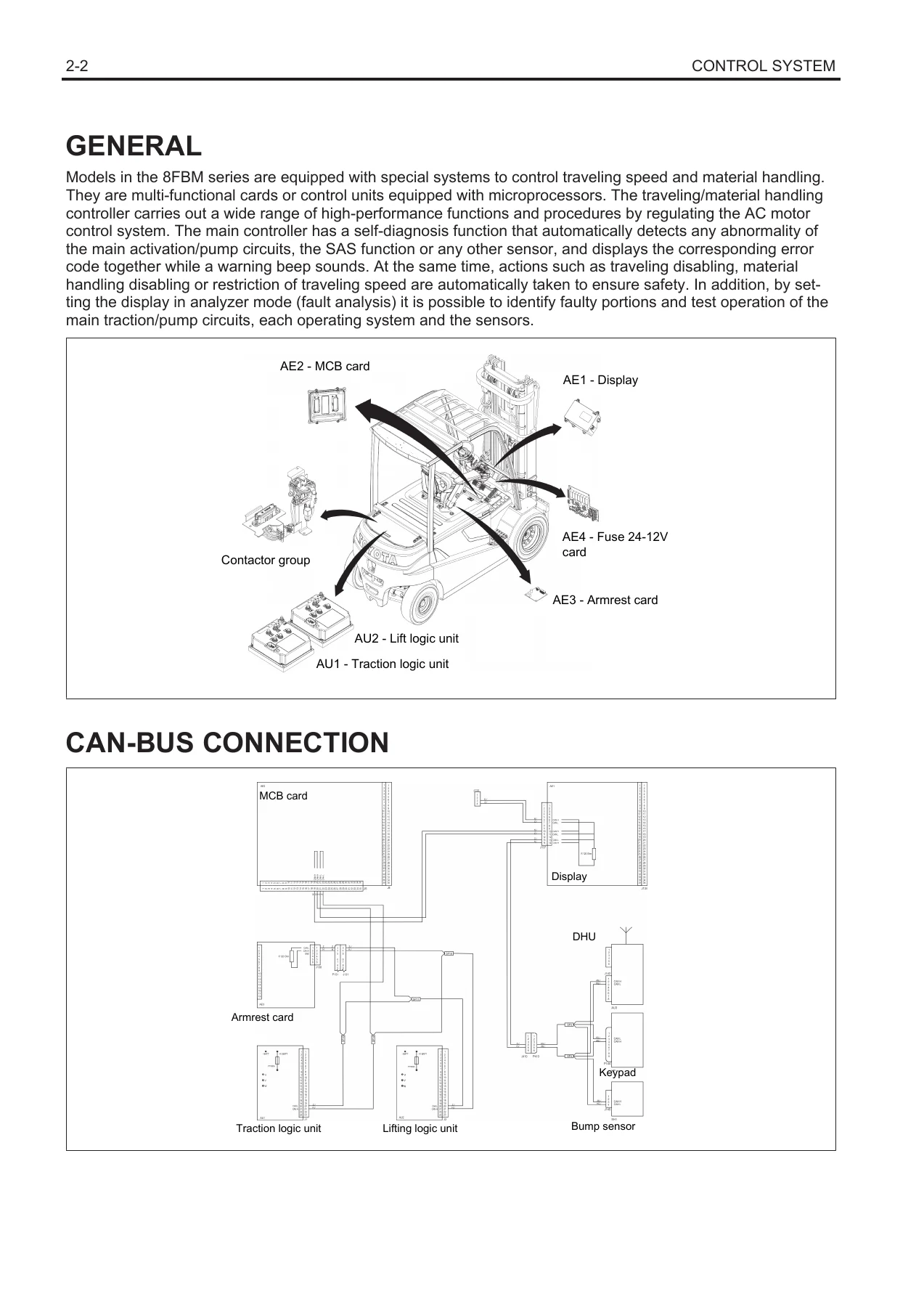
  • 2 CONTROL SYSTEM β€” general, CAN-bus connection, rear compartment fuses, fuses under dashboard, contactors, DC/DC converters, logic units, contactor group, MCB card, multi-display functions, 24-12 V fuse card, armrest card, armrest card potentiometers, accelerator potentiometer, steering potentiometer, tilt angle potentiometer, mast pressure sensor, mast height switch, yaw rate sensor, calibrations
  • 3 MULTI-FUNCTION DISPLAY β€” general, menu map, operator menu, administrator menu, mask menu, analyzer, tuning, option set, matching, others menu
  • 4 TROUBLESHOOTING β€” connector check, wire harness and connectors inspection procedure, insulation check procedure, motor winding check procedure, temperature sensor check procedure, CAN-bus check procedure, diagnostic codes list, when an error code is displayed
  • 5 MOTOR β€” drive motor general specifications, disassembly / inspection / assembly, temperature sensor replacing, pump motor general, pump motor specifications, disassembly / assembly, encoder replacing, temperature sensor replacing
  • 6 DRIVE UNIT & FRONT AXLE β€” general, components standard version, components negative brake version, front axle assembly, maintenance (oil top-up, draining and changing the oil)
  • 7 REAR AXLE β€” rear axle assembly, specifications, components, wheels, rear axle, rear axle hub and cast articulated joint, rear axle cylinder
  • 8 STEERING β€” scraper specifications, steering column, orbitrol, inspection and adjustment, troubleshooting
  • 9 BRAKE β€” general, specifications, components, brake unit, parking brake, negative brake version and emergency negative brake release
  • 10 BODY β€” components, operator’s seat, battery cover unit, overhead guard, counterweight, rear chassis
  • 11 MATERIAL HANDLING SYSTEM β€” hydraulic circuit, negative brake hydraulic diagram, components, oil tank, oil filter and air breather pipe, hydraulic oil, lifting load down test, natural forward tilting test, oil leak test
  • 12 MAST β€” mast, fork carriage assembly and mast removal, mast group with fork carriage, mast assembly V, mast group FV, mast group FSV, FW mast group (OPT), FSW mast group (OPT), lifting bracket V-FV-FSV, lifting bracket FW-FSW (OPT), replacing the fork carriage guide pads, adjusting the mast V-FV-FSV, standard for selecting an oversize roller, mast roller, chains, fork, adjusting the adjusting rings on the lift cylinder rod
  • 13 CYLINDER β€” lifting cylinders (side and central, by mast type and capacity), lowering valve specifications, parachute valve, components, side lifting cylinder assembly, central lifting cylinder assembly, tilting cylinders, disassembly / inspection / reassembly
  • 14 OIL PUMP β€” scraper, specifications, components, disassembly / assembly
  • 15 OIL CONTROL VALVE β€” hydraulic diagram, components, section breakdown (lift, tilting, ATT1, ATT2, outer rail), specifications, disassembly / assembly, maximum pressure adjustment
  • 16 SAS FUNCTION β€” general SAS system description and sensor/actuator matrix, hand grip position correction valve, steering potentiometer, tilt angle potentiometer, mast pressure sensor, mast height switch, yaw rate sensor, oscillation lock cylinder, adjustment and calibration requirements
  • 17 MAIN OPTIONS β€” DC/DC converters, rear compartment fuses, fuses under dashboard, height selector, bump sensor / DHU / keypad, flash and rotating lamp, work spotlights, combined lights, heater and heated rear window, windscreen wipers, radio, cab light
  • 18 APPENDIX β€” component reference with illustration and wiring-diagram references, wiring reading method, colour codes, and the individual wiring harnesses (remote control switches, steering column with key and with keypad, standard armrest, mast pressure sensor, 5th way valve, tilting pedal, TWIS system, windscreen washer tank, flash / rotating lamp, front lights, front LED lights, rear lights, front working lights, rear working lights, lights on mast, front and rear windscreen wiper, heater unit, car radio, overhead light, cigarette lighter)

Complete PDF Bookmark Tree

Complete Bookmarks

The complete bookmarks in the β€œToyota 8FBMT40 8FBMT45 8FBMT50 Forklift Repair Manual – CE370” are as follows:

GENERALp. 5
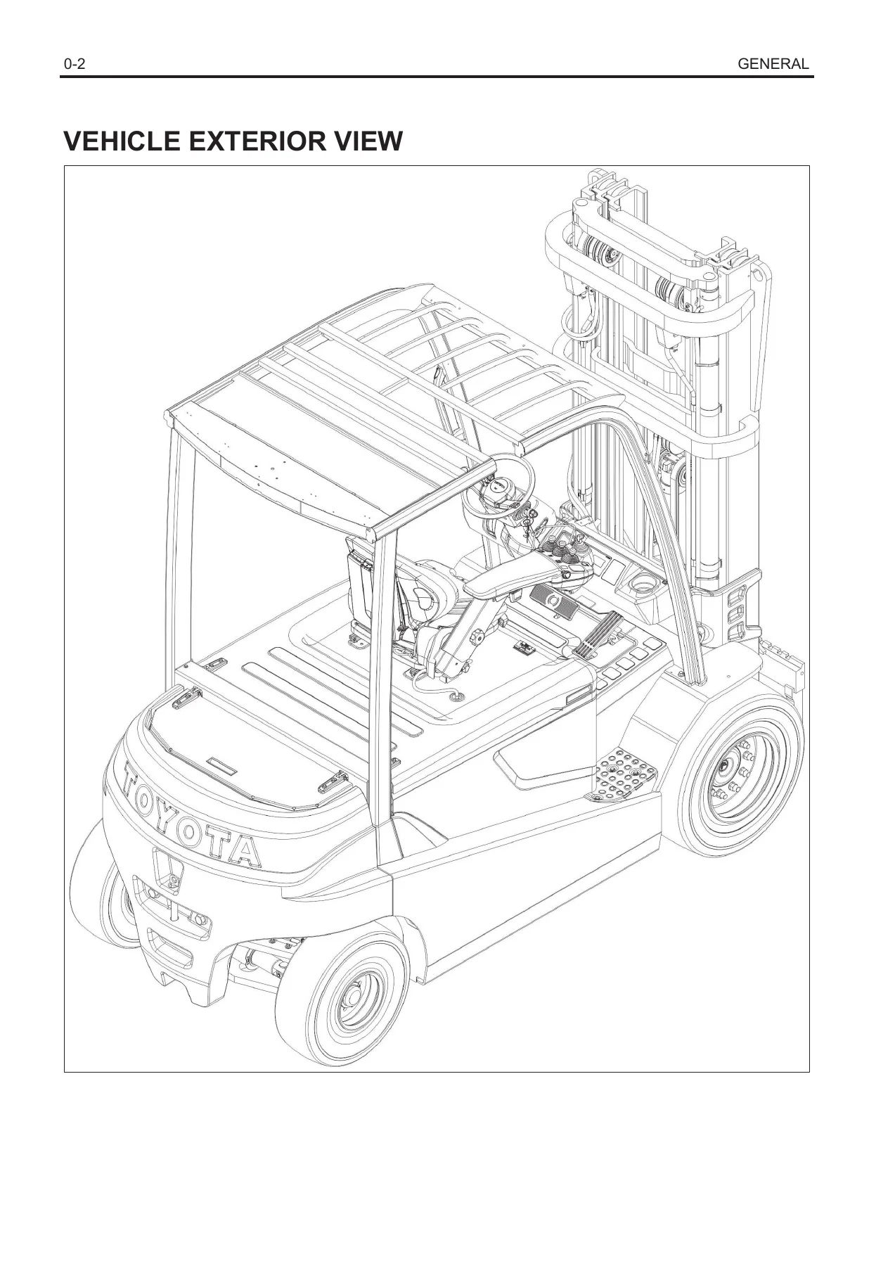
VEHICLE EXTERIOR VIEWp. 6
VEHICLE MODELSp. 6
CHASSIS NUMBERp. 7
HOW TO USE THIS MANUALp. 7
EXPLANATION METHODp. 7
TERMINOLOGYp. 8
ABBREVIATIONSp. 8
SI UNITSp. 8
OPERATING TIPSp. 9
JACK-UP POINTSp. 10
LIFTING THE VEHICLEp. 10
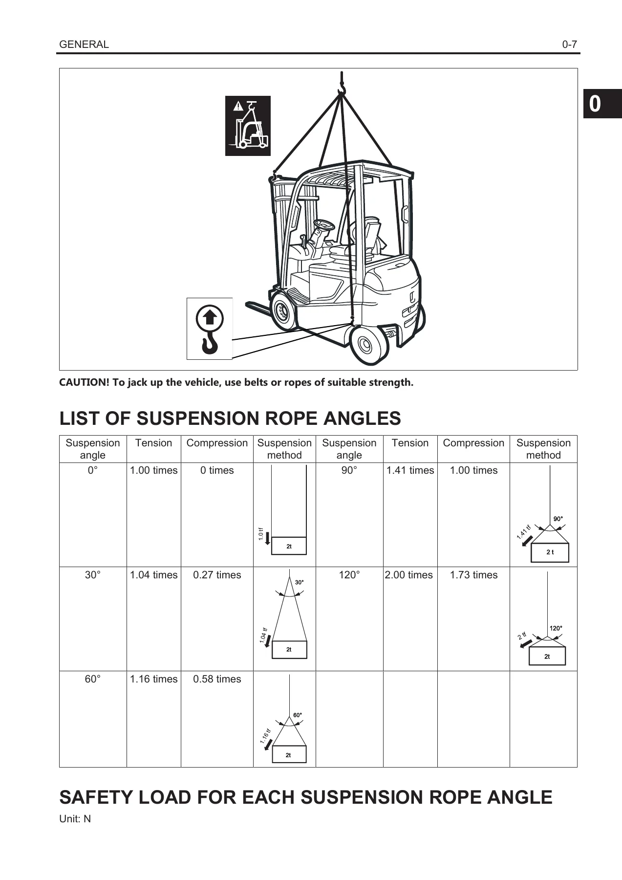
LIST OF SUSPENSION ROPE ANGLESp. 11
SAFETY LOAD FOR EACH SUSPENSION ROPE ANGLEp. 11
COMPONENT WEIGHTSp. 12
TOWING THE TRUCKp. 12
ELECTRICAL COMPONENTS INSPECTIONp. 12
NOTES ON SASp. 13
TIGHTENING TORQUE TABLEp. 14
TABLE OF LUBRICANTS AND FLUIDSp. 14
PERIODIC MAINTENANCEp. 15
General Indicationsp. 15
Periodic Replacements Tablep. 15
Periodic Maintenance Tablep. 16
SAS Periodic maintenancep. 20
Lubrication Chartp. 22
BATTERYp. 23
BATTERY COMPARTMENT AND REQUIRED WEIGHTp. 24
STANDARD SERVICE VALUESp. 24
MULTI-DISPLAY FUNCTIONSp. 24
Battery charge indicatorp. 24
Insufficient battery charge alarmp. 25
STATE OF BATTERY CHARGE INDICATORp. 25
PROCEDURE SET TEMPERATURE SENSOR BATTERYp. 25
BATTERY MANAGEMENT PARAMETERSp. 27
TABLE OF BDI MAX, BDI MIN, RESET VOLT VALUESp. 29
BATTERY INDICATOR TROUBLESHOOTINGp. 30
TROUBLESHOOTINGp. 31
BATTERY UNITp. 33
DISASSEMBLY-ASSEMBLYp. 34
INSPECTIONp. 34
* Battery control tablep. 35
STATE OF BATTERY CHARGEp. 36
BATTERY CAPACITYp. 37
Discharge ratep. 37
Electrolyte specific gravityp. 37
Electrolyte temperaturep. 37
Battery agep. 37
GEL BATTERIESp. 37
REPLACING BATTERY PLUG TERMINALSp. 38
CONTROL SYSTEMp. 41
GENERALp. 42
CAN-BUS CONNECTIONp. 42
REAR COMPARTMENT FUSESp. 42
FUSES UNDER DASHBOARDp. 43
CONTACTORSp. 44
DC/DC CONVERTERSp. 45
LOGIC UNITSp. 46
DISASSEMBLY-ASSEMBLYp. 47
CONTACTOR GROUPp. 47
DISASSEMBLY-ASSEMBLYp. 48
MCB CARDp. 48
DISASSEMBLY-ASSEMBLYp. 49
MULTI-DISPLAY FUNCTIONSp. 49
DISASSEMBLY-ASSEMBLYp. 50
24-12 V FUSE CARDp. 50
DISASSEMBLY-ASSEMBLYp. 51
ARMREST CARDp. 51
DISASSEMBLY-ASSEMBLYp. 52
ARMREST CARD POTENTIOMETERSp. 52
DISASSEMBLY-ASSEMBLYp. 53
ACCELERATOR POTENTIOMETERp. 53
DISASSEMBLY-ASSEMBLYp. 54
STEERING POTENTIOMETERp. 55
DISASSEMBLY-ASSEMBLYp. 55
Point Operationsp. 55
[Point 1]p. 56
[Point 2]p. 56
TILT ANGLE POTENTIOMETERp. 56
DISASSEMBLY-ASSEMBLYp. 57
Point Operationsp. 57
[Point 1]p. 57
MAST PRESSURE SENSORp. 57
DISASSEMBLY-ASSEMBLYp. 58
MAST HEIGHT SWITCHp. 58
DISASSEMBLY-ASSEMBLYp. 59
YAW RATE SENSORp. 59
DISASSEMBLY-ASSEMBLYp. 59
CALIBRATIONSp. 60
MULTI-FUNCTION DISPLAYp. 63
GENERALp. 64
Display and buttonsp. 64
Initializing screenp. 65
MENU MAPp. 65
OPERATOR MENUp. 66
ADMINISTRATOR MENUp. 67
Password menup. 67
Password entry procedurep. 67
ADMINISTRATOR menu screenp. 68
Symbolsp. 69
ADMINISTRATOR menu screen (with vehicle startup using key)p. 69
POWER CONTROLp. 71
TRACTION SETTINGp. 72
MATERIAL HANDLINGp. 73
TRUCK MANAGEMENTp. 76
SHOCK SENSORp. 77
ADMINISTRATOR menu screen (with vehicle startup using pin code via keypad)p. 79
PIN ENTRYp. 81
PROFILE SETTING – POWER CONTROLp. 83
PROFILE SETTING – TRACTION SETTINGp. 84
PROFILE SETTING – MATERIAL HANDLING SETTINGp. 85
MATERIAL HANDLINGp. 88
TRUCK MANAGEMENTp. 88
SHOCK SENSORp. 89
MASK MENUp. 90
Mask menu passwordp. 90
MASK MENU screenp. 91
ANALYZERp. 92
ANALYZER MENU screenp. 96
1. DIAG MEMORYp. 97
2. I/O TEMP/VOLTp. 99
3. I/O TRAVELINGp. 100
4. I/O M. HANDLINGp. 102
5. I/O STEERINGp. 104
6. I/O OTHERSp. 104
7. ACTIVE TESTp. 105
8. SW VERSIONp. 105
TUNINGp. 106
TUNING MENU screenp. 108
1. TRACTIONp. 110
2. M. HANDLINGp. 117
3. VALVE SASp. 121
4. LIFT VALVEp. 122
5. TILT VALVEp. 123
6. ATT1 VALVEp. 124
7. ATT2 valvep. 126
8. ATT3 VALVEp. 127
OPTION SETp. 128
OPTION SET screenp. 131
1. OPTIONSETp. 133
2. MAINTENANCEp. 136
3. RENT TIMEp. 137
4. BATTERYp. 138
5. TWIS FLAGp. 139
6. ROT LAMP 1p. 140
7. ROT LAMP 2p. 142
8. FLASH LAMPp. 143
9. DIPPED LIGHTp. 144
10. WORK LAMPp. 145
11. WIPERS/WASHERp. 145
12. DIR LIGHTSp. 146
13. HEATERp. 147
MATCHINGp. 147
MATCHING screenp. 149
1. SERIAL NUMBERp. 151
2. DRIVEp. 151
3. MINI LEVERp. 154
4. SASp. 157
5. LOAD METERp. 160
6. H-SELECTORp. 162
7. ADJUST BATTERYp. 163
8. TIRE DATAp. 165
9. ELT BRAKEp. 166
OTHERS MENUp. 166
OTHERS MENU screenp. 167
1. METER STARTp. 168
2. DEMO MODEp. 169
3. TO DEFAULT SETp. 169
4. MASK PASSWORDp. 173
5. MANAGER PASSp. 174
6. CONTRASTp. 175
7. DELUXE MODEp. 175
TROUBLESHOOTINGp. 177
CONNECTOR CHECKp. 178
BEFORE TROUBLESHOOTINGp. 178
WIRE HARNESS AND CONNECTORS INSPECTION PROCEDUREp. 178
Continuity checkp. 178
Short circuit checkp. 178
Visual and contact pressure checksp. 179
INSULATION CHECK PROCEDUREp. 179
Truck insulation checkp. 179
Battery insulation checkp. 180
Motor insulation checkp. 180
MOTOR WINDING CHECK PROCEDUREp. 180
Motor phase continuity checkp. 180
TEMPERATURE SENSOR CHECK PROCEDUREp. 180
Sensor integrity checkp. 181
Sensor insulation checkp. 181
CAN-BUS CHECK PROCEDUREp. 181
Software version checkp. 181
Wiring harness and connections checkp. 182
DIAGNOSTIC CODES LISTp. 183
WHEN AN ERROR CODE IS DISPLAYEDp. 194
TRACTION LOGIC UNITp. 195
201p. 195
202p. 195
203p. 195
204p. 196
205p. 197
206p. 198
207p. 199
208p. 200
209p. 201
20Ap. 202
20Bp. 202
20Cp. 202
20Dp. 202
20Ep. 203
210p. 204
211p. 205
212p. 206
213p. 206
214p. 207
215p. 208
216p. 209
217p. 209
218p. 210
219p. 210
21Ap. 211
21Bp. 212
21Cp. 213
21Dp. 214
21Ep. 215
21Fp. 216
220p. 217
221p. 218
222p. 219
223p. 220
224p. 220
225p. 221
226p. 222
227p. 223
228p. 224
229p. 224
22Ap. 225
22Bp. 226
22Cp. 227
22Dp. 228
22Ep. 228
22Fp. 229
230p. 229
231p. 230
232p. 231
233p. 232
234p. 232
235p. 233
236p. 233
237p. 233
238p. 234
239p. 235
23Ap. 236
23Bp. 237
23Cp. 238
23Dp. 238
23Ep. 238
23Fp. 239
240p. 239
241p. 240
242p. 240
243p. 241
244p. 241
245p. 242
246p. 242
247p. 243
251p. 243
253p. 244
254p. 244
255p. 245
256p. 246
257p. 247
258p. 247
25Ap. 248
25Bp. 248
25Cp. 249
25Dp. 249
260p. 249
261p. 250
262p. 250
MCB CARD (TRCB section)p. 251
45Ap. 251
45Cp. 251
494p. 252
496p. 252
4B6p. 253
4C1p. 253
4C3p. 253
4C4p. 254
4C5p. 255
4C6p. 256
4C7p. 257
4C8p. 257
4C9p. 258
4CAp. 258
4CBp. 258
4CCp. 259
4CDp. 259
4CFp. 259
4F1p. 259
4F2p. 260
4F5p. 261
4FAp. 262
4FBp. 263
4FCp. 264
4FDp. 265
4FEp. 265
LIFT LOGIC UNITp. 266
501p. 266
502p. 266
503p. 267
504p. 267
505p. 268
506p. 269
507p. 270
508p. 271
509p. 272
50Ap. 273
50Bp. 273
50Cp. 273
50Dp. 273
50Ep. 274
510p. 275
511p. 276
512p. 277
513p. 277
514p. 278
515p. 279
516p. 279
517p. 280
518p. 280
519p. 280
51Ap. 280
51Bp. 281
51Cp. 282
51Dp. 283
51Ep. 284
51Fp. 285
520p. 285
521p. 285
522p. 285
523p. 285
524p. 286
525p. 287
526p. 288
527p. 289
528p. 290
529p. 290
52Ap. 291
52Bp. 292
52Cp. 292
52Dp. 293
52Ep. 293
52Fp. 294
530p. 294
531p. 295
532p. 296
533p. 297
534p. 297
535p. 297
536p. 298
537p. 298
538p. 298
539p. 299
53Ap. 300
53Bp. 301
53Cp. 301
53Dp. 302
53Ep. 302
53Fp. 303
540p. 303
541p. 303
542p. 304
543p. 304
544p. 304
545p. 305
546p. 305
547p. 306
551p. 306
553p. 307
554p. 307
555p. 308
556p. 309
557p. 310
558p. 310
55Ap. 311
55Bp. 311
55Cp. 312
55Dp. 312
560p. 312
561p. 313
562p. 313
MCB CARD (EVCB section)p. 313
659p. 314
65Ap. 314
65Bp. 315
65Dp. 316
65Ep. 317
6A1p. 318
6A2p. 318
6A3p. 319
6A4p. 319
6A7p. 319
6A8p. 320
6A9p. 320
6AAp. 321
6ABp. 322
6ACp. 323
6ADp. 324
6AEp. 325
6AFp. 326
6B0p. 327
6B1p. 327
6B2p. 328
6B3p. 329
6B4p. 330
6B6p. 331
6B7p. 331
6B8p. 331
6BAp. 332
6BBp. 332
6BCp. 333
6BDp. 334
6BEp. 335
6E1p. 336
6EEp. 336
6F3p. 336
6F4p. 337
ARMREST CARD (section Master)p. 337
8E1p. 337
8E2p. 337
8E3p. 337
8E4p. 338
8E5p. 338
8E6p. 339
8E7p. 339
8E8p. 339
8E9p. 340
8EAp. 340
8EBp. 340
8ECp. 341
8EDp. 341
8EEp. 341
MULTI-DISPLAY FUNCTIONSp. 342
C02p. 342
C04p. 342
C05p. 343
C06p. 343
C08p. 344
C0Bp. 344
CB9p. 345
CD1p. 345
CD3p. 345
CD7p. 345
CD9p. 346
CDAp. 346
CDCp. 347
CDDp. 347
CDEp. 347
CDFp. 347
CF1p. 348
CF2p. 348
CF3p. 349
ARMREST CARD (section Slave)p. 349
BE6p. 350
BE7p. 350
BE8p. 350
BE9p. 351
BEAp. 351
BEBp. 352
BECp. 352
MOTORp. 353
SENSORp. 354
GENERALp. 354
SPECIFICATIONSp. 354
DISASSEMBLYΒ·INSPECTIONΒ·ASSEMBLYp. 354
Point Operationsp. 356
TEMPERATURE SENSOR REPLACINGp. 365
DISASSEMBLY-ASSEMBLYp. 365
PUMP MOTOR:p. 366
GENERALp. 366
SPECIFICATIONSp. 366
COMPONENTSp. 367
DISASSEMBLY-ASSEMBLYp. 368
Point Operationsp. 369
ENCODER REPLACINGp. 369
TEMPERATURE SENSOR REPLACINGp. 370
Point Operationsp. 371
DRIVE UNIT & FRONT AXLEp. 373
GENERALp. 374
COMPONENTS – STANDARD VERSIONp. 374
COMPONENTS – NEGATIVE BRAKE VERSIONp. 376
FRONT AXLE ASSEMBLYp. 378
DISASSEMBLYβ€’ASSEMBLYp. 379
Point Operationsp. 379
MAINTENANCEp. 380
OIL TOP-UPp. 381
DRAINING AND CHANGING THE OILp. 381
REAR AXLEp. 383
REAR AXLE ASSEMBLYp. 384
GENERALp. 384
SPECIFICATIONSp. 384
COMPONENTSp. 385
WHEELSp. 386
SPECIFICATIONSp. 387
REAR AXLEp. 387
DISASSEMBLY-ASSEMBLYp. 388
Point Operationsp. 388
REAR AXLE HUB – CAST ARTICULATED JOINTp. 389
DISASSEMBLY-ASSEMBLYp. 390
Point Operationsp. 390
REAR AXLE CYLINDERp. 394
DISASSEMBLY-ASSEMBLY-INSPECTIONp. 394
Point Operationsp. 395
STEERINGp. 397
SCRAPERp. 398
STEERING COLUMNp. 398
DISASSEMBLYβ€’ASSEMBLYp. 399
Point Operationsp. 399
ORBITROLp. 400
DISASSEMBLYβ€’ASSEMBLYp. 401
Point Operationsp. 401
TROUBLESHOOTINGp. 402
BRAKEp. 405
GENERALp. 406
SPECIFICATIONSp. 406
COMPONENTSp. 406
BRAKE UNITp. 407
PARKING BRAKEp. 407
BRAKE PEDALp. 408
BRAKE UNITp. 410
DISASSEMBLYΒ·INSPECTIONΒ·ASSEMBLYp. 411
Point Operationsp. 412
[Point 1]p. 413
[Point 2]p. 413
[Point 3]p. 414
[Point 4]p. 414
[Point 5]p. 414
[Point 6]p. 414
[Point 7]p. 415
[Point 8]p. 415
[Point 9]p. 415
[Point 10]p. 415
[Point 11]p. 416
[Point 12]p. 416
[Point 13]p. 416
[Point 14]p. 416
[Point 15]p. 417
[Point 16]p. 417
[Point 17]p. 417
[Point 18]p. 418
[Point 19]p. 418
[Point 20]p. 419
[Point 21]p. 419
[Point 22]p. 419
[Point 23]p. 420
[Point 24]p. 420
[Point 25]p. 420
[Point 26]p. 421
[Point 27]p. 421
[Point 28]p. 421
[Point 29]p. 421
[Point 30]p. 422
[Point 31]p. 422
[Point 32]p. 422
[Point 33]p. 423
[Point 34]p. 423
[Point 35]p. 423
[Point 36]p. 424
[Point 37]p. 424
[Point 38]p. 425
[Point 39]p. 425
[Point 40]p. 426
[Point 41]p. 426
[Point 42]p. 426
[Point 43]p. 427
[Point 44]p. 427
[Point 45]p. 427
[Point 46]p. 428
[Point 47]p. 428
[Point 48]p. 428
[Point 49]p. 429
[Point 50]p. 429
[Point 51]p. 429
[Point 52]p. 429
[Point 53]p. 430
[Point 54]p. 430
[Point 55]p. 430
[Point 56]p. 430
[Point 57]p. 431
[Point 58]p. 431
[Point 59]p. 431
[Point 60]p. 432
PARKING BRAKEp. 432
DISASSEMBLYΒ·ASSEMBLYΒ·ADJUSTMENTp. 433
NEGATIVE BRAKE VERSIONp. 433
COMPONENTSp. 434
EMERGENCY NEGATIVE BRAKE RELEASEp. 434
BODYp. 435
COMPONENTSp. 436
OPERATOR’S SEATp. 452
DISASSEMBLY-ASSEMBLYp. 452
BATTERY COVER UNITp. 452
DISASSEMBLY-ASSEMBLYp. 453
OVERHEAD GUARDp. 453
DISASSEMBLY-ASSEMBLYp. 454
COUNTERWEIGHTp. 454
DISASSEMBLY-ASSEMBLYp. 455
REAR CHASSISp. 455
DISASSEMBLY-ASSEMBLYp. 456
MATERIAL HANDLING SYSTEMp. 457
HYDRAULIC CIRCUITp. 458
NEGATIVE BRAKE HYDRAULIC DIAGRAMp. 458
COMPONENTSp. 459
GENERALp. 460
OIL TANKp. 460
CONTROL VALVEp. 461
STEERING SYSTEMp. 462
NEGATIVE BRAKE SYSTEMp. 463
V MASTp. 463
FV MASTp. 464
FSV MASTp. 465
FW MASTp. 466
FSW MASTp. 467
OIL TANKp. 468
REMOVALβ€’ INSTALLATIONp. 469
OIL FILTER AND AIR BREATHER PIPEp. 469
REMOVALβ€’ INSTALLATIONp. 470
Point Operationsp. 470
HYDRAULIC OILp. 471
REPLACEMENTp. 472
LIFTING LOAD DOWN TESTp. 472
NATURAL FORWARD TILTING TESTp. 473
OIL LEAK TESTp. 473
LIFT CYLINDERp. 474
TILTING CYLINDERSp. 474
MASTp. 475
MASTp. 476
GENERALp. 476
MAST SECTIONp. 478
MAST SECTION (OPT)p. 479
COMPONENTSp. 480
MAST GROUP (V) (4.0 – 5.0 t)p. 481
MAST GROUP (FV) (4.0 – 4.5 t)p. 481
MAST GROUP (FV) (5.0 t)p. 481
MAST GROUP (FSV) (4.0 – 4.5 t)p. 482
MAST GROUP (FSV) (5.0 t)p. 482
MAST GROUP (FW) (4.0 – 4.5 t) (OPT)p. 483
MAST GROUP (FW) (5.0 t) (OPT)p. 483
MAST GROUP (FSW) (4.0 – 4.5 t) (OPT)p. 484
MAST GROUP (FSW) (5.0 t) (OPT)p. 485
LIFTING BRACKET GROUP (V) (4.0 – 5.0 t)p. 485
LIFTING BRACKET GROUP (FV) (4.0 – 4.5 t)p. 486
LIFTING BRACKET GROUP (FV) (5.0 t)p. 486
LIFTING BRACKET GROUP (FSV) (4.0 – 4.5 t)p. 487
LIFTING BRACKET GROUP (FSV) (5.0 t)p. 487
LIFTING BRACKET GROUP (FW) (4.0 – 5.0 t) (OPT)p. 488
LIFTING BRACKET GROUP (FSW) (4.0 – 5.0 t) (OPT)p. 488
SIDESHIFT FORK CARRIAGE GROUP (V) (4.0 – 5.0 t)p. 489
SIDESHIFT FORK CARRIAGE GROUP (FV) (4.0 – 4.5 t)p. 489
SIDESHIFT FORK CARRIAGE GROUP (FV) (5.0 t)p. 490
SIDESHIFT FORK CARRIAGE GROUP (FSV) (4.0 – 4.5 t)p. 490
SIDESHIFT FORK CARRIAGE GROUP (FSV) (5.0 t)p. 491
SIDESHIFT FORK CARRIAGE GROUP (FW) (4.0 – 5.0 t) (OPT)p. 491
SIDESHIFT FORK CARRIAGE GROUP (FSW) (4.0 – 5.0 t) (OPT)p. 492
CHAIN AND CHAIN PULLEY GROUP (V) (4.0 – 5.0 t)p. 492
CHAIN AND CHAIN PULLEY GROUP (FV) (4.0 – 4.5 t)p. 493
CHAIN AND CHAIN PULLEY GROUP (FV) (5.0 t)p. 493
CHAIN AND CHAIN PULLEY GROUP (FSV) (4.0 – 4.5 t)p. 494
CHAIN AND CHAIN PULLEY GROUP (FSV) (5.0 t)p. 494
CHAIN AND CHAIN PULLEY GROUP (FW) (4.0 – 5.0 t) (OPT)p. 495
CHAIN AND CHAIN PULLEY GROUP (FSW) (4.0 – 5.0 t) (OPT)p. 495
FORK CARRIAGE ASSEMBLY AND MAST REMOVALp. 496
DISASSEMBLY-ASSEMBLYp. 496
Point Operationsp. 497
[Point 1]p. 497
[Point 2]p. 498
[Point 3]p. 499
[Point 4]p. 499
MAST GROUP (WITH FORK CARRIAGE)p. 499
DISASSEMBLY-ASSEMBLYp. 500
Point Operationsp. 500
[Point 1]p. 501
[Point 2]p. 501
MAST ASSEMBLY Vp. 501
DISASSEMBLYΒ·INSPECTIONΒ·ASSEMBLYp. 502
Point Operationsp. 502
[Point 1]p. 503
[Point 2]p. 503
MAST GROUP FVp. 503
DISASSEMBLYΒ·INSPECTIONΒ·ASSEMBLYp. 504
Point Operationsp. 504
[Point 1]p. 505
[Point 2]p. 505
MAST GROUP FSVp. 505
DISASSEMBLYΒ·INSPECTIONΒ·ASSEMBLYp. 506
Point Operationsp. 506
[Point 1]p. 507
[Point 2]p. 507
FW MAST GROUP (OPT)p. 507
DISASSEMBLYΒ·INSPECTIONΒ·ASSEMBLYp. 508
Point Operationsp. 508
[Point 1]p. 509
FSW MAST GROUP (OPT)p. 509
DISASSEMBLYΒ·INSPECTIONΒ·ASSEMBLYp. 509
Point Operationsp. 510
[Point 1]p. 510
LIFTING BRACKET V – FV – FSVp. 510
DISASSEMBLYΒ·INSPECTIONΒ·ASSEMBLYp. 511
Point Operationsp. 511
[Point 1]p. 511
LIFTING BRACKET FW – FSW (OPT)p. 512
DISASSEMBLYΒ·INSPECTIONΒ·ASSEMBLYp. 512
Point Operationsp. 512
[Point 1]p. 513
REPLACING THE FORK CARRIAGE GUIDE PADSp. 513
DISASSEMBLYΒ·INSPECTIONΒ·ASSEMBLYp. 513
Point Operationsp. 514
[Point 1]p. 514
[Point 2]p. 514
ADJUSTING THE MAST V β€’ FV β€’ FSVp. 516
Adjusting the lifting roller on the mastp. 516
Adjusting the play on the inner mast roller (V – FV – FSV) and central mast lower roller (FSV)p. 516
Adjusting the play on the outer mast roller (V – FV – FSV) and central mast upper roller (FSV)p. 516
Adjusting the roller on the fork platep. 517
Adjusting the play on the lower/central/upper lifting rollerp. 518
Adjusting the lifting roller on the mastp. 518
Adjusting the clearance of the inner mast rollerp. 519
STANDARD FOR SELECTING AN OVERSIZE ROLLERp. 519
MAST ROLLERp. 520
DISASSEMBLY-ASSEMBLYp. 520
CHAINSp. 520
INSPECTIONS – INSTALLATION – TUNINGp. 521
Standard values of the chain pitch distancep. 521
Assemblyp. 521
Adjustmentp. 523
FORKp. 525
DISASSEMBLYΒ·INSPECTIONΒ·ASSEMBLYp. 525
ADJUSTING THE ADJUSTING RINGS ON THE LIFT CYLINDER ROD (TO AVOID IRREGULAR LIFTING)p. 527
CYLINDERp. 529
LIFTING CYLINDERSp. 530
GENERALp. 530
SPECIFICATIONSp. 532
PARACHUTE VALVE (LOWERING SAFETY VALVE)p. 534
LOWERING VALVEp. 534
COMPONENTSp. 534
SIDE LIFTING CYLINDERS V MAST (4.0 – 4.5 t)p. 535
SIDE LIFTING CYLINDERS V MAST (5.0 t)p. 535
SIDE LIFTING CYLINDERS FV MAST (4.0 – 4.5 t)p. 535
CENTRAL LIFTING CYLINDERS FV MAST (4.0 – 4.5 t)p. 536
SIDE LIFTING CYLINDERS FV MAST (5.0 t)p. 536
CENTRAL LIFTING CYLINDERS FV MAST (5.0 t)p. 537
SIDE LIFTING CYLINDERS FSV MAST (4.0 – 4.5 t)p. 537
CENTRAL LIFTING CYLINDERS FSV MAST (4.0 – 4.5 t)p. 538
SIDE LIFTING CYLINDERS FSV MAST (5.0 t)p. 538
CENTRAL LIFTING CYLINDERS FSV MAST (5.0 t)p. 539
FW MAST SIDE LIFTING CYLINDERS (4.0 – 4.5 t) (OPT)p. 539
FW MAST CENTRAL LIFTING CYLINDERS (4.0 – 4.5 t) (OPT)p. 540
FW MAST SIDE LIFTING CYLINDERS (5.0 t) (OPT)p. 540
FW MAST CENTRAL LIFTING CYLINDERS (5.0 t) (OPT)p. 541
FSW MAST SIDE LIFTING CYLINDER (4.0 – 4.5 t) (OPT)p. 541
FSW MAST CENTRAL LIFTING CYLINDER (4.0 – 4.5 t) (OPT)p. 542
FSW MAST SIDE LIFTING CYLINDERS (5.0 t) (OPT)p. 542
FSW MAST CENTRAL LIFTING CYLINDERS (5.0 t) (OPT)p. 543
SIDE LIFTING CYLINDER ASSEMBLYp. 543
DISASSEMBLYβ€’ASSEMBLYp. 544
CYLINDER (V – FSV) (FSW (OPT))p. 546
REMOVAL – INSPECTION – INSTALLATIONp. 547
Point Operationsp. 547
CYLINDER (FV) (FW (OPT))p. 550
REMOVAL – INSPECTION – INSTALLATIONp. 551
Point Operationsp. 551
CENTRAL LIFTING CYLINDER ASSEMBLYp. 556
DISASSEMBLYβ€’ASSEMBLYp. 557
CYLINDER (FV – FSV) (FW (OPT) – FSW (OPT))p. 558
REMOVAL – INSPECTION – INSTALLATIONp. 559
TILTING CYLINDERSp. 563
GENERALp. 564
SPECIFICATIONSp. 564
COMPONENTSp. 564
DISASSEMBLYβ€’ASSEMBLYp. 565
Adjustingp. 566
DISASSSEMBLY β€’ INSPECTION β€’ REASSEMBLYp. 566
Point Operationsp. 567
OIL PUMPp. 571
SCRAPERp. 572
COMPONENTSp. 573
DISASSEMBLY-ASSEMBLYp. 573
Point Operationsp. 575
[Point 1]p. 575
[Point 2]p. 575
[Point 3]p. 575
[Point 4]p. 575
OIL CONTROL VALVEp. 577
HYDRAULIC DIAGRAMp. 578
COMPONENTSp. 578
SPECIFICATIONSp. 583
DISASSEMBLY-ASSEMBLYp. 583
MAXIMUM PRESSURE ADJUSTMENTp. 584
SAS FUNCTIONp. 587
GENERALp. 588
FOR REPAIR WORKp. 589
HAND GRIP POSITION CORRECTION VALVEp. 589
DISASSEMBLY-ASSEMBLYp. 590
STEERING POTENTIOMETERp. 590
DISASSEMBLY-ASSEMBLYp. 591
Point Operationsp. 591
TILT ANGLE POTENTIOMETERp. 592
DISASSEMBLY-ASSEMBLYp. 593
Point Operationsp. 593
MAST PRESSURE SENSORp. 594
DISASSEMBLY-ASSEMBLYp. 594
MAST HEIGHT SWITCHp. 594
DISASSEMBLY-ASSEMBLYp. 595
YAW RATE SENSORp. 595
DISASSEMBLY-ASSEMBLYp. 596
OSCILLATION LOCK CYLINDERp. 596
DISASSEMBLY-ASSEMBLYp. 597
Point Operationsp. 598
ADJUSTMENTp. 599
GENERALp. 599
MAIN OPTIONSp. 601
DC/DC CONVERTERSp. 602
REAR COMPARTMENT FUSESp. 602
FUSES UNDER DASHBOARDp. 603
HEIGHT SELECTORp. 604
COMPONENTSp. 605
FUNCTIONSp. 606
MAXIMUM HEIGHT LIMITERp. 606
HEIGHT LIMITERp. 606
AUTOMATIC HEIGHT CONTROLp. 607
BUMP SENSOR – DHU – KEYPADp. 609
COMPONENTSp. 610
FLASH – ROTATING LAMPp. 610
COMPONENTSp. 611
WORK SPOTLIGHTSp. 611
COMPONENTSp. 612
COMBINED LIGHTSp. 612
COMPONENTSp. 613
HEATER – HEATED REAR WINDOWp. 613
COMPONENTSp. 614
WINDSCREEN WIPERS – RADIO – CAB LIGHTp. 614
COMPONENTSp. 615
APPENDIXp. 617
COMPONENTSp. 618
IMAGE 1p. 625
IMAGE 2p. 626
IMAGE 3p. 627
IMAGE 4p. 628
IMAGE 5p. 629
IMAGE 6p. 630
IMAGE 7p. 631
WIRING DIAGRAMp. 632
WIRINGp. 640
READING METHODp. 641
MAIN HARNESSp. 641
REMOTE CONTROL SWITCHES WIRING HARNESSp. 664
STEERING COLUMN WIRING HARNESS WITH KEYp. 669
STEERING COLUMN WIRING HARNESS WITH KEYPADp. 672
STANDARD ARMREST WIRING HARNESSp. 674
MAST PRESSURE SENSOR WIRING HARNESSp. 679
5th WAY VALVE HARNESSp. 680
TILTING PEDAL WIRINGp. 681
TWIS SYSTEM WIRING HARNESSp. 681
WINDSCREEN WASHER TANK HARNESSp. 684
FLASH / ROTATING LAMP WIRINGp. 685
FRONT LIGHTS WIRING HARNESSp. 686
FRONT LED LIGHTS WIRINGp. 687
REAR LIGHTS WIRING HARNESSp. 688
FRONT WORKING LIGHTS WIRING HARNESSp. 691
REAR WORKING LIGHTS WIRING HARNESSp. 692
WIRING HARNESS FOR LIGHTS ON MASTp. 693
FRONT AND REAR WINDSCREEN WIPER WIRINGp. 694
HEATER UNIT WIRINGp. 696
CAR RADIO WIRINGp. 697
OVERHEAD LIGHT WIRING HARNESSp. 699
CIGARETTE LIGHTER WIRING HARNESSp. 699

Read as a whole, this Toyota 8FBMT40 8FBMT45 8FBMT50 forklift repair manual gives a technician a single continuous source for the whole truck: the mechanical chapters take the drive unit, front axle, rear axle, brake, steering, mast and cylinders down to individual seals, bearings, shims and torque figures, while the electrical and electronic chapters deal with the traction logic unit, lift logic unit, MCB card, armrest card, multi-function display, sensors and the CAN-bus network. The troubleshooting chapter lists the diagnostic codes by card and number together with the checks each code calls for, so a fault shown on the display can be traced back to a specific connector, coil, sensor or cable. Tightening torques, adjustment limits and wear limits are given throughout at the point where the operation is described rather than collected in one place at the back, which is how the factory arranged this document.

Specifications, Adjustments and Wear Limits

The specification content is spread across the machine rather than confined to a single data section. Motor chapters carry voltage, power, current, frequency, speed, power factor, efficiency, IP protection, cooling class, service rating and connection type for both the drive motor and the pump motor. The mast chapters cover mast section ranges by mast type, chain pitch distances and stretch limits, roller clearances and the oversize roller selection table, fork wear and alignment limits, and the shimming procedure used to stop uneven lifting between the right and left cylinders. The hydraulic chapters give cylinder bore and piston rod diameters, parachute valve settings, control valve set drain pressure and flow regulator rates, while the brake chapter states the disc stack arrangement and the oil quantities for the oil bath and service brakes. Body chapters give the counterweight, rear chassis, overhead guard and front axle tightening torques.

Diagnostics and Wiring

Diagnostic coverage in this Toyota 8FBMT40 8FBMT45 8FBMT50 repair manual is built around the truck’s own self-diagnosis. The diagnostic codes list is organised by the card that reports the alarm β€” traction logic unit, MCB card TRCB and EVCB sections, lifting logic unit, multi-display functions and the armrest card master and slave sections β€” and each code is described with the conditions that trigger it and the components or connections to check. Supporting procedures cover connector inspection, wire harness continuity, insulation checks on the truck, the battery and the motors, motor winding continuity, temperature sensor resistance and the CAN-bus line. The appendix then supplies the wiring harness drawings with connector pin tables and colour codes for the main circuits, including the armrest, steering column, lighting, wiper, heater, radio and TWIS harnesses, plus the connector location illustrations.

What This Manual Enables You to Do

With this Toyota 8FBMT40 8FBMT45 8FBMT50 forklift repair manual on hand you can strip and rebuild the drive unit and front axle, service the rear axle hub and cast articulated joint, reseal the steering cylinder, rework the wet disc brake unit, replace mast rollers and chains, reseal the lifting and tilting cylinders, take the oil pump and oil control valve apart, and set the maximum pressure back to specification. On the electrical side you can replace the logic units and cards, swap potentiometers and sensors, calibrate them through the multi-function display menus, read and clear the diagnostic memory, and work through the harness and connector checks that the fault codes point to. Working from the correct procedures and the printed torque, clearance and wear values is what keeps a four to five tonne counterbalance truck safe to lift with, so using the factory method rather than guesswork matters more here than on almost any other machine.

IMAGES PREVIEW

Toyota 8FBMT40 8FBMT45 8FBMT50 Forklift Repair Manual - CE370 β€” PDF page 6 preview
Toyota 8FBMT40 8FBMT45 8FBMT50 Forklift Repair Manual - CE370 β€” PDF page 11 preview
Toyota 8FBMT40 8FBMT45 8FBMT50 Forklift Repair Manual - CE370 β€” PDF page 42 preview

This Toyota 8FBMT40 8FBMT45 8FBMT50 forklift repair manual is delivered as an instant PDF download after payment, with no shipping and no waiting for a disc to arrive. The file opens on a workshop PC, a laptop, a tablet or a phone, and any page you need for the job in front of you can be printed and taken to the truck.
Reviews

There are no reviews yet.

Be the first to review “Toyota 8FBMT40 8FBMT45 8FBMT50 Forklift Repair Manual – CE370”

What Our Customers Say

β˜…β˜…β˜…β˜…β˜… Live reviews from customers
Loading customer reviews...
0
    0
    Your Cart
    Your cart is emptyReturn to Shop
    πŸ›’
    Recently Purchased
    πŸ•’ verified order