
Toyota 7FBR10-18 Electric Forklift Electrical Repair Manual Volume 2 CE352
Original price was: $39.95.$23.95Current price is: $23.95.
Electrical repair manual for Toyota 7FBR10, 7FBR13, 7FBR15 and 7FBR18 electric forklifts. Volume 2 covers the controller, multifunction display DX, diagnosis-code driven troubleshooting and the complete electric wiring diagram. 409 pages, English, PDF.
Description
File Details
- Manual type: Electrical Repair Manual (Volume 2)
- Brand: Toyota
- Models covered: 7FBR10, 7FBR13, 7FBR15, 7FBR18
- Publication number: CE352
- Edition/date: 1st Printing, July 2012
- Language: English
- Page count: 409 pages
- File format: PDF
Chapters Covered
The Toyota 7FBR10-18 Electric Forklift Electrical Repair Manual Volume 2 CE352 is built around four service areas that give an electric forklift technician everything needed to trace, test and repair the 48 V electrical system on the reach trucks.
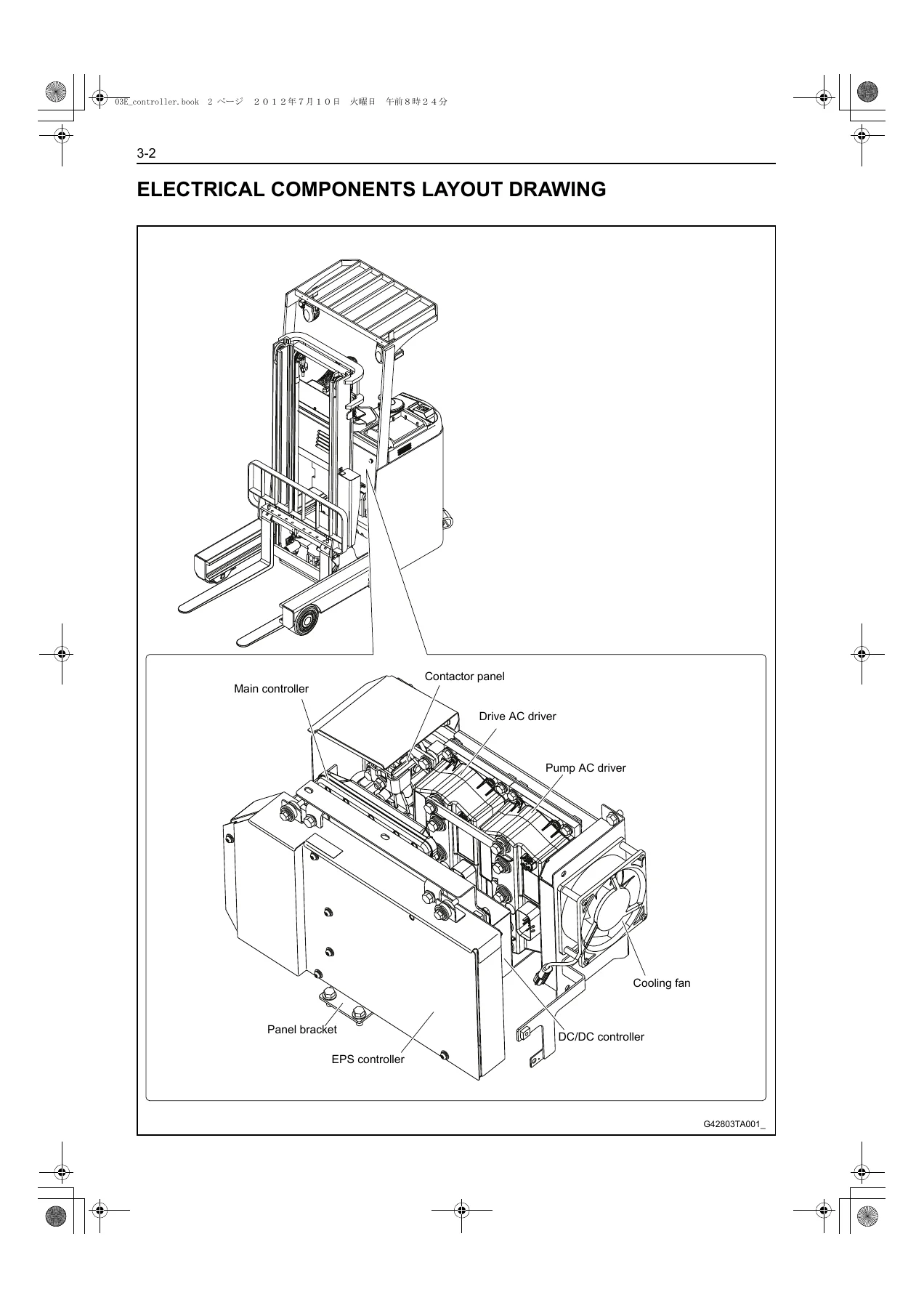
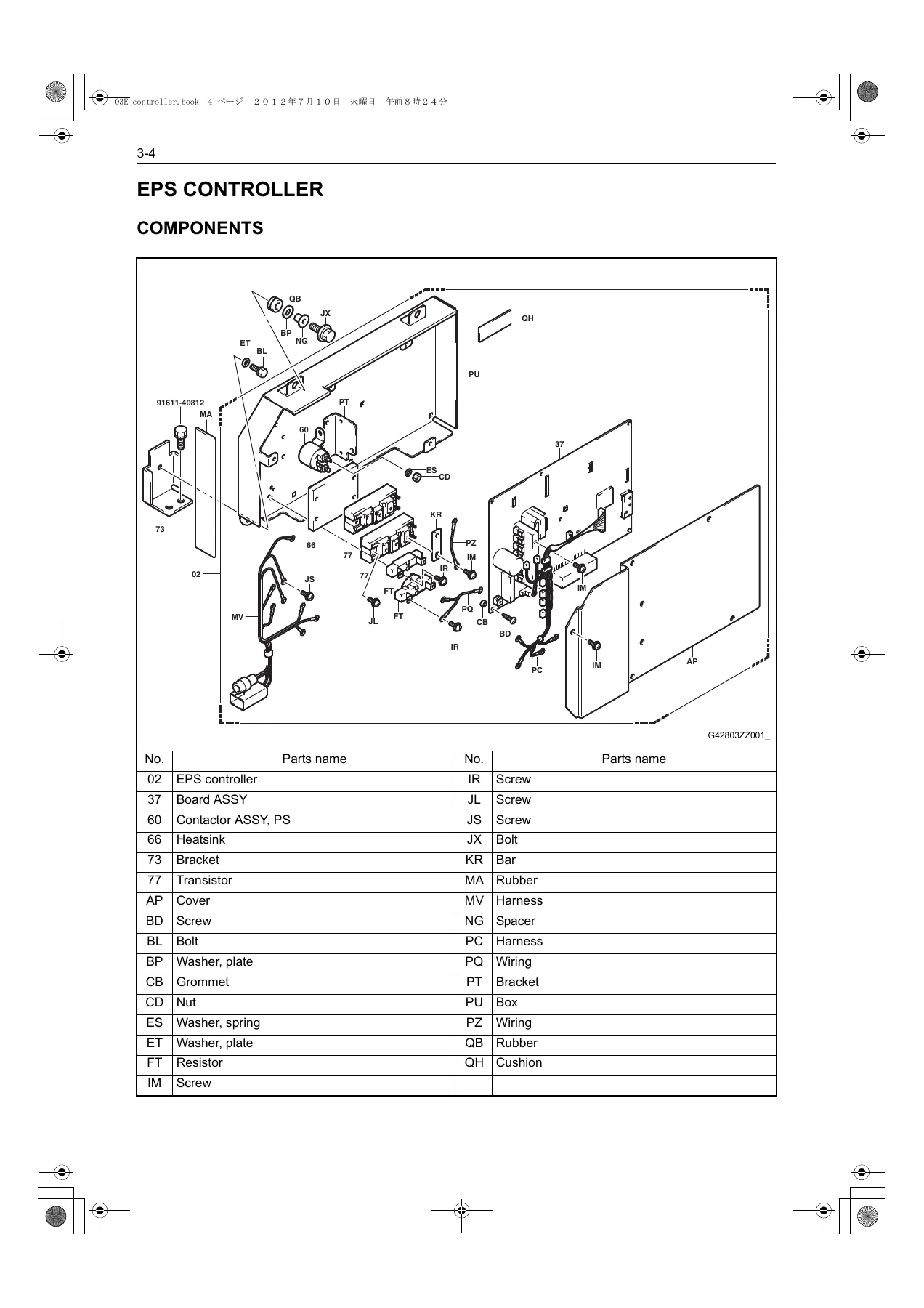
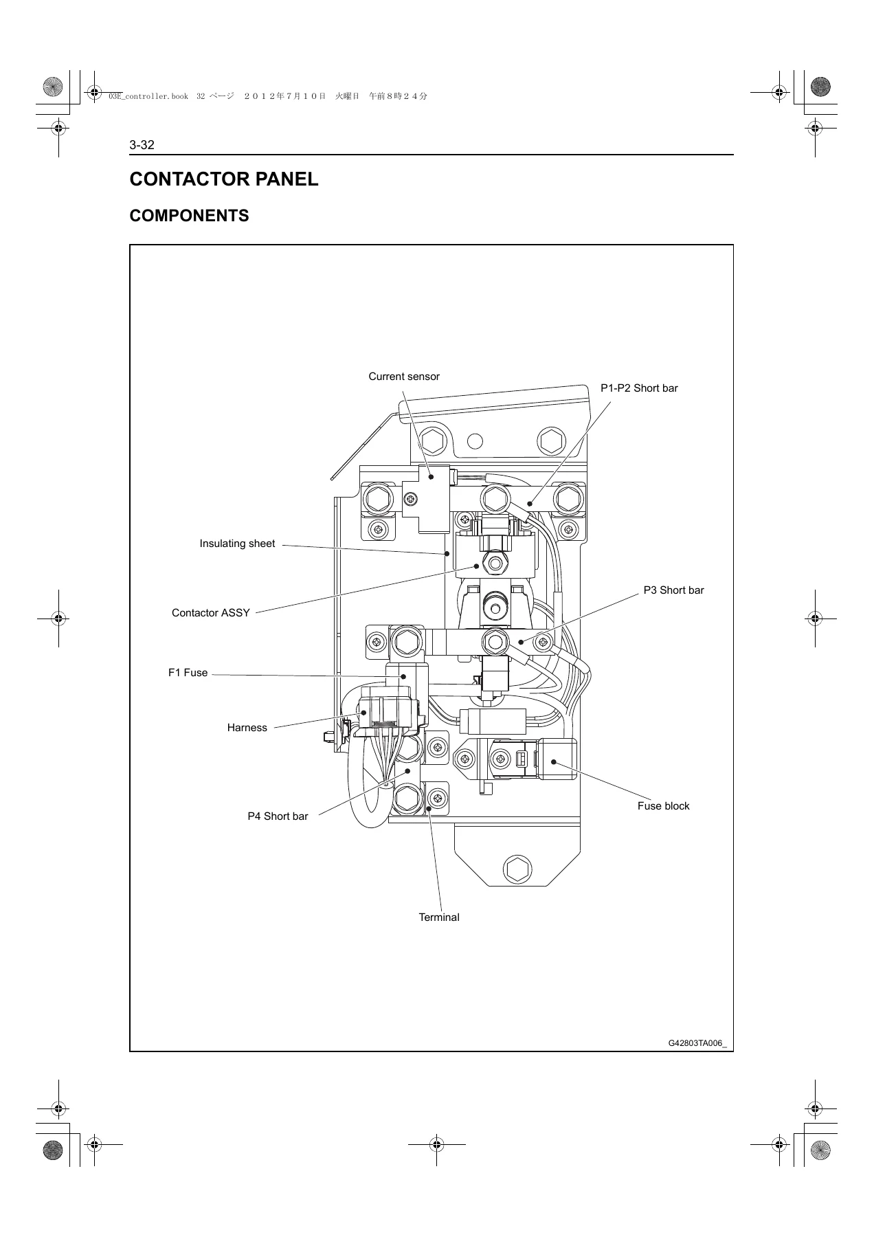
- Controller (Section 3) — electrical components layout drawing, controller cable routing, EPS controller components, main controller components and connector pin assignment (A24, A25, A26, A27), connector inspection procedure with basic-condition voltage tables, removal and installation of the main controller, drive and pump AC drivers, contactor panel components, contactor panel installation, contactor panel insulating-resistance test, accelerator lever general description, components, removal and installation, limit switch installation procedure and OCL measurement (drive and pump circuits).
- Display (Section 4) — multifunction display DX general description, indicator details, battery capacity indicator, administrator functions and password entry, service functions list, service password entry, operation of the service menu screens, analyzer menu (DIAG MEMORY, I/O TEMP/VOLT, I/O TRAVELING, I/O M.HANDLING, I/O STEERING, I/O OTHERS, ACTIVE TEST, VERSION), tuning menu (GENERAL, LIFT LEVER, TILT LEVER, REACH LEVER, ATT1 LEVER, ATT2 LEVER), option set, matching menu (DRIVE, SAS, LOAD METER, TIRE DATA) and the others menu (METER START, DEMO MODE, TO DEFAULT SET, MASK PASSWORD, MANAGER PASS CLR, CHARGER CNT CLR, CONTRAST).
- Troubleshooting (Section 5) — before-troubleshooting precautions, connector handling, wire harness and connector inspection procedure (continuity, short-circuit, visual and contact-pressure checks), SST setting methods, EPS controller connector component layout, full diagnosis code list with lamp, indicator and related-connector references, and error-code-by-error-code flow charts covering A0, A1, A2, A3, A5, A6, A8, AA, AB, AC, AD, AF, C0, C1, C2, C3, C4, C8, CB, CC, E0, E1, E2, E3, E8, EC, EE, EF, F0, F1, F4, F5, F6, F7, F8, FB, FC, FE, FF, G1, G2, G3, 32, 33, 51, 54, 56, 61, 64, 67, 71, 72, 74 and 75 codes plus a ‘when no error code is displayed’ table for power-supply, traveling, load handling, PS, OPS, TBC, display and on-vehicle charger symptoms.
- Electric Wiring Diagram (Section 21) — introduction and chapter guide, electrical wiring routings and relay locations (front body, rear body, instrument panel, mast area for V, SV, FV and FSV masts), relay locations (front body, rear body, contactor panel and AC driver, CAN J/C), system circuits (power supply, charger, drive and material handling control, OPS and TBC, EPS, multifunction display and PIN code entry system, horn, headlight, turn signal light, back buzzer, laser marker, ground point), connector list and wire-to-wire connector list, connecting diagram and full wiring diagram with wire colours, connector codes and relay-block internal circuits.
This is the second volume of the Toyota 7FBR10 to 18 service set. Volume 1 (CE351) carries the chassis, body, mast, hydraulic and material-handling mechanical content — the sections that this electrical volume references but does not reprint. What this volume does contain is the complete electrical side of the truck: how the main controller, EPS controller and DC/DC controller talk to each other over CAN, what each pin on every controller connector is expected to read under the basic conditions, how the display’s analyser and active-test tools expose live sensor data, and how every circuit runs from the battery through the contactor panel and fuses to the loads and back to the N1 ground.
Diagnostic System and Error Codes
The diagnostic part of the manual is where most of a technician’s time gets saved. The diagnosis code list maps each fault (for example AD-1 and AD-2 for drive AC driver to main controller communication, A5-1 for a floor-switch GND short, C4-1 through C4-5 for accelerator potentiometer faults, 51-1 through 51-5 for front and rear speed sensor faults, CB-1 through CB-5 for MB contactor faults and G3-1 for the accumulator pressure switch) to a lamp and indicator state, the connectors involved and the page where the fault-tree flowchart sits. Every flow chart follows the same logic — verify the connector, verify the harness continuity and shorts, verify the sensor or actuator in isolation, verify the controller, and only then condemn the module. That structure is what keeps a technician from replacing a controller that is actually being fed a bad sensor signal.
Controller and Connector Reference Data
For pin-level work, the connector inspection tables give the basic-condition voltages for each terminal with the battery plug connected and the key switch ON. Examples include A24-18 (VBBA) at approximately 48 V, A24-27 (POTA+) to A24-32 (POT-) at approximately 5 V with the accelerator in neutral, A25-24 (CSBAT) to A25-35 (CSBAT-) at approximately 2.5 V, A26-14 (D7V) to A26-3 (DGND) at approximately 6.5 V, A27-3 (CBAT+) to A27-9 (CBAT-) at approximately 11 V with the key on, and the accelerator potentiometer outputs on A25-30 and A25-32 reading approximately 2.3 V in neutral and sweeping between approximately 0.5 V and 4 V across the lever stroke. Matching these readings against the manual’s expected values is the fastest way to separate a wiring fault from a component fault before any parts get ordered.
Display, Service Functions and Matching
The multifunction display DX section is written from the service technician’s seat. It documents the analyser so a technician can pull live sensor voltages and switch states without a breakout box, the active test so the swing lock solenoid, brake valves and cooling fan can be commanded on and off from the display, the tuning screens for adjusting acceleration and regenerative braking feel, the option-set screens for matching the display to the truck’s actual configuration, and the matching screens for the accelerator, tire angle, steering torque, load meter and tire data — all of which must be performed after replacing the corresponding sensor or controller.
Wiring Diagram and Routing
The wiring section carries the routing for the main harness, accelerator harness, instrument panel harness, lamp harness, control valve limit switch harness, mast harness, motor sensor harness and the FR speed wires, plus the front-body, rear-body, instrument-panel and mast-area relay locations. The wiring diagram itself is colour coded and connector-coded, with the junction block and relay block internal circuits drawn alongside — so a technician can follow a wire from the battery through the F1, F3, F4, F5, F6 or F7 fuse, through the MB and MPS contactors, out to the AC drivers or EPS controller and back to the relevant ground point.
Why This Manual Matters for the 7FBR Series
Electric reach trucks are controller-driven machines. A fault in the accelerator potentiometer can shut the truck down exactly like a fault in the drive AC driver, and the only way to tell the difference without swapping parts is to follow the diagnostic path and the pin-level voltage references. The Toyota 7FBR10-18 Electric Forklift Electrical Repair Manual Volume 2 CE352 puts both of those on the same page as the wiring diagram, so a technician can move from a symptom on the display straight to the connector under test, measure against the values the manual lists, and repair the fault rather than replace it.
Whether you are tracing an intermittent CAN communication code, performing a controller replacement and matching procedure, measuring the OCL value on the drive circuit with a clamp meter, or working through the electrical routing to add or fault-find a charger or laser marker circuit, this volume is the reference that supports the job from start to finish.
Delivered instantly as a PDF after checkout, no shipping and no waiting. Read it on a laptop or tablet in the workshop, print only the pages you need for the truck in front of you, and keep the whole 409-page volume on hand for every 7FBR10, 7FBR13, 7FBR15 and 7FBR18 that comes through the bay.
IMAGES PREVIEW

Reviews
There are no reviews yet.