
★ TRUSTED BY 321,897+ PROFESSIONALS WORLDWIDE
🏢
Trusted Business
Verified & Licensed
🛡️
Virus Free Files
100% Safe Downloads
🔒
Secure Payment
SSL Protected
Instant Delivery
Available Immediately
Sale!

2021 Bobcat T76 Compact Track Loader Service Manual 7323984 – B4CE11001 & Above

Original price was: $44.95.Current price is: $26.95.

Complete 904-page service manual for the Bobcat T76 Compact Track Loader, serial B4CE11001 & Above. Covers maintenance, hydraulic and hydrostatic systems, drive and undercarriage service, mainframe repairs, electrical diagnostics, engine service, HVAC, specifications, service tools, schematics, testing, removal and installation, disassembly, assembly and adjustment procedures.

Instant PDF Download
Available immediately
💾
Save to Your Device
Download & keep forever
🛡️
Antivirus Scanned
100% virus-free
🌍
Trusted Worldwide
175,000+ customers

Description

2021 Bobcat T76 Compact Track Loader Service Manual 7323984 – B4CE11001 & Above

This 2021 Bobcat T76 Compact Track Loader Service Manual 7323984 – B4CE11001 & Above is a detailed service and repair reference for the T76 compact track loader. The manual is written for loader mechanics and provides servicing and adjustment procedures for the machine, its component parts and its major systems. Across 904 pages it moves from routine maintenance and safe service preparation into hydraulic and hydrostatic testing, track and drive repairs, mainframe work, electrical diagnostics, engine service, HVAC procedures and machine specifications.

The manual goes well beyond routine maintenance. Component-level procedures include testing, removal and installation, parts identification, disassembly, assembly, pressure checks, adjustments and troubleshooting. Technical illustrations, component photographs, hydraulic and hydrostatic schematics, exploded views and service data are used throughout the Bobcat T76 service manual to support workshop diagnosis and repair.

File Details

  • Manual type: Service Manual
  • Brand: Bobcat
  • Model: T76 Compact Track Loader
  • Serial coverage: B4CE11001 & Above
  • Document number: 7323984enUS
  • Revision/date: 08-21 (D)
  • Language: English
  • Pages: 904
  • File format: PDF

Workshop Service and Diagnostic Coverage

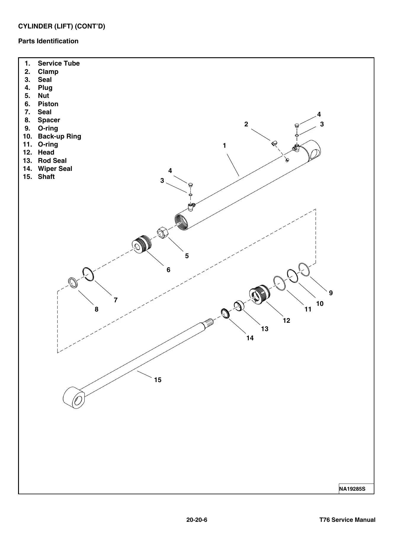
The Bobcat T76 Compact Track Loader Service Manual 7323984 is structured around the systems a technician encounters during inspection, diagnosis and repair. Hydraulic coverage includes system information, troubleshooting, lift and tilt cylinders, Bob-Tach cylinders, the main relief valve, hydraulic control valve, lift arm bypass control, standard and high-flow hydraulic pumps, filters, reservoir, oil cooler, auxiliary hydraulic components and automatic ride control. Procedures include cylinder testing and rebuilding, pump tests, relief-pressure checks, valve service and hydraulic component removal and installation.

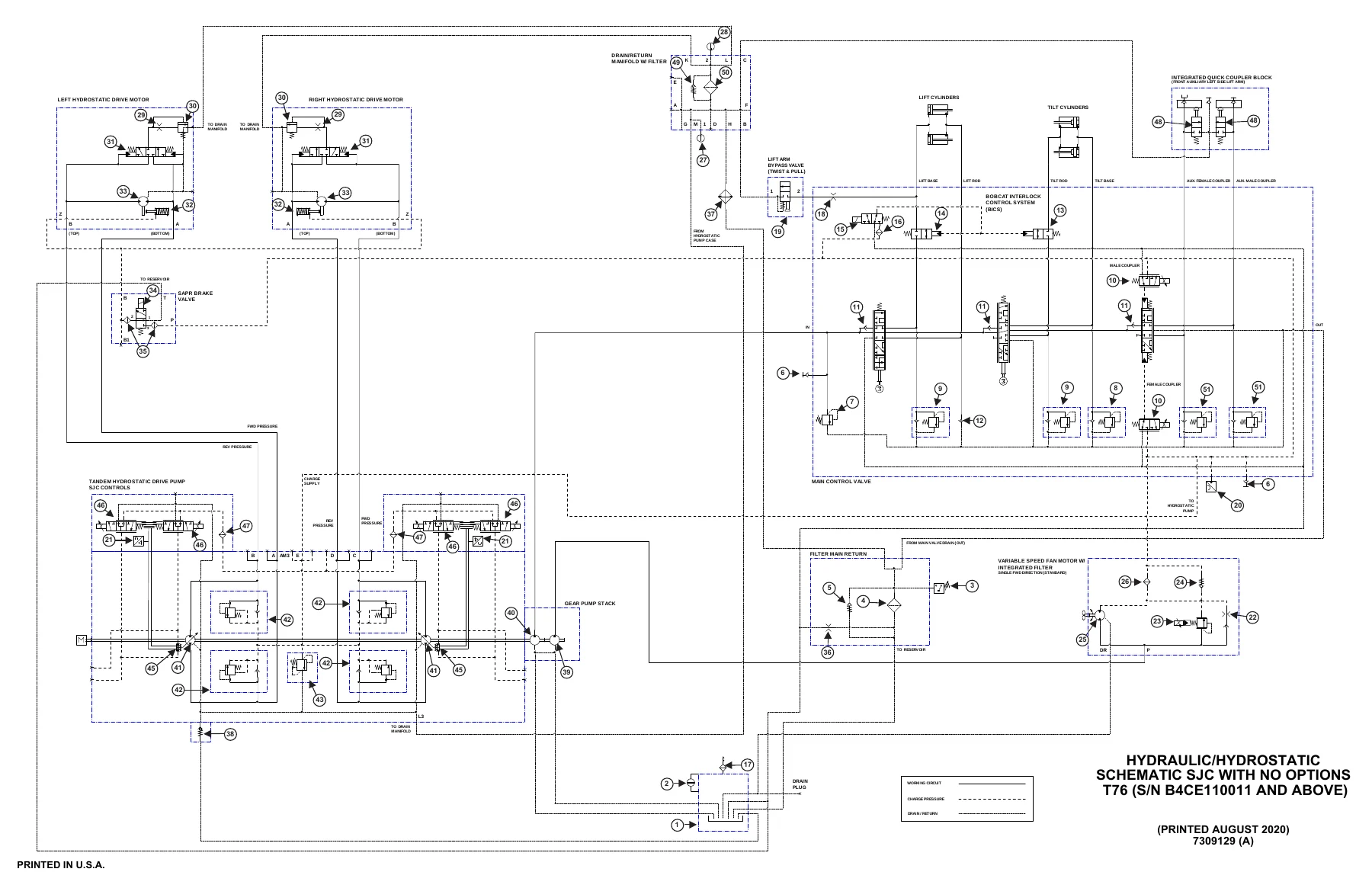
The hydrostatic section covers the hydrostatic drive system, drive motors, charge pressure, hydrostatic pump, two-speed and brake valve and drain manifold. It includes troubleshooting, fluid service, pressure testing, pump service, mechanical and hydraulic neutral adjustment and component disassembly and assembly. Detailed hydraulic/hydrostatic schematics are included for the T76, supporting circuit tracing and system diagnosis.

Drive-system information addresses the brake system and both solid-mounted and torsion-suspension track undercarriage configurations. Track tension checking and adjustment, track removal and installation, idlers, tensioners, rollers, sprockets, track frames and track damage inspection are covered. This makes the manual useful for repairs that extend from basic track maintenance to major undercarriage component service.

Mainframe procedures cover the seat bar, operator cab, seats, Bob-Tach assemblies, lift arms, rear grille, rear door, fuel tank, footrest, SJC control handles, access panels and cab windows. Procedures are supported by photographs and illustrations showing service locations, fasteners, pivots and component arrangements.

Electrical, Engine and HVAC Service

The electrical section provides coverage of the battery, alternator, starter, instrument panels, lights, Bobcat controllers, SJC drive controller, engine control unit, diagnostic service codes, Bobcat Interlock Control System, seat bar sensing and traction lock. It also covers electrical/hydraulic SJC controls, Service PC procedures, calibration, steering drift compensation, display navigation and settings, maintenance clock, alarms, horn and engine speed controls. This combination of service-code information, controller coverage and calibration procedures gives technicians a direct path from an electrical or control-system symptom to the relevant testing and service information.

Engine service includes engine information, diesel oxidation catalyst, air cleaner, cooling and lubrication systems, fuel system, cylinder head, crankshaft and pistons, camshaft, gearcase, turbocharger, flywheel and housing, exhaust gas recirculation system and exhaust manifold. The specification section identifies the engine as the Bobcat Engine / 2,4L Bobcat Engine Tier 4, a four-cylinder diesel with turbocharging and charged-air cooling. Engine procedures are supported by service data, torque information and dedicated engine service tools listed in the manual.

Heating, ventilation and air-conditioning coverage includes air-conditioning system flow, regular maintenance, troubleshooting, system charging and reclamation, compressor, condenser, receiver / drier, HVAC assembly, thermostat, expansion valve, evaporator coil, heater coil, blower fan, heater valve and automatic HVAC module. These sections provide service procedures for both mechanical HVAC components and the controls associated with the system.

Chapters Covered

  • Foreword
    • Safety instructions and fire prevention
    • Serial number locations
    • Delivery report and loader identification

    Complete PDF Bookmark Tree

    Complete Bookmarks

    The complete bookmarks in the “2021 Bobcat T76 Compact Track Loader Service Manual 7323984 – B4CE11001 & Above” are as follows:

    MAINTENANCE SAFETYp. 3
    CONTENTSp. 5
    FOREWORDp. 7
    FOREWORDp. 9
    SAFETY INSTRUCTIONSp. 11
    FIRE PREVENTIONp. 13
    Maintenancep. 13
    Operationp. 13
    Electricalp. 13
    Hydraulic Systemp. 13
    Fuelingp. 13
    Startingp. 13
    Spark Arrester Exhaust Systemp. 13
    Welding And Grindingp. 14
    Fire Extinguishersp. 14
    SERIAL NUMBER LOCATIONSp. 15
    Machine Serial Number Locationp. 15
    Engine Serial Number Locationp. 15
    DELIVERY REPORTp. 16
    LOADER IDENTIFICATIONp. 17
    SAFETY & MAINTENANCEp. 19
    LIFTING AND BLOCKING THE LOADERp. 23
    Procedurep. 23
    LIFT ARM SUPPORTp. 25
    Lift Arm Support Descriptionp. 25
    Installing Lift Arm Supportp. 25
    Removing Lift Arm Supportp. 27
    OPERATOR CABp. 29
    Inspecting Operator Cabp. 29
    Cab Door Sensor Descriptionp. 29
    Raising Operator Cabp. 30
    Lowering Operator Cabp. 31
    Clear Side Enclosed Cab Optionp. 33
    Inspecting And Maintaining Clear Side Enclosed Cab Optionp. 33
    Special Applications Kitp. 34
    Inspecting And Maintaining Special Applications Kitp. 34
    Forestry Door And Window Kitp. 35
    Inspecting And Maintaining Forestry Door And Window Kitp. 35
    TRANSPORTING THE LOADER ON A TRAILERp. 37
    Loading And Unloading Machinep. 37
    Fastening Machine To Transport Vehiclep. 38
    TOWING THE LOADERp. 39
    Procedurep. 39
    REMOTE START TOOL (SERVICE TOOL) KIT – 7217666p. 41
    Descriptionp. 41
    Remote Start Tool (Service Tool) – 7022042p. 42
    Loader Service Tool Harness – 6689747p. 43
    Computer Service Tool Harness – 6689746p. 44
    Remote Start Procedurep. 45
    SERVICE SCHEDULEp. 49
    Maintenance Intervalsp. 49
    Service Schedule Symbolsp. 52
    ENGINE AIR CLEANERp. 53
    Replacing Engine Air Filter Element (Outer)p. 53
    Replacing Engine Air Filter Element (Inner)p. 54
    ENGINE COOLING SYSTEMp. 55
    Cleaning Engine Cooling Systemp. 55
    Checking And Adding Coolantp. 57
    Replacing Coolantp. 58
    FUEL SYSTEMp. 61
    Fuel Specificationsp. 61
    Biodiesel Blend Fuelp. 61
    Filling The Fuel Tankp. 62
    Removing Water From Main Fuel Filterp. 63
    Replacing Fuel Pre-Filterp. 64
    Replacing Main Fuel Filterp. 65
    Replacing Fuel Tank Vent Filterp. 67
    ENGINE LUBRICATION SYSTEMp. 69
    Checking And Adding Engine Oilp. 69
    Engine Oil Chartp. 69
    Replacing Engine Oil And Filterp. 70
    HYDRAULIC SYSTEMp. 73
    Checking And Adding Hydraulic Fluidp. 73
    Hydraulic Fluid Chartp. 74
    Replacing Hydraulic Fluidp. 75
    Replacing Main Hydraulic Filterp. 79
    Replacing Hydraulic Case Drain Filterp. 81
    Replacing Hydraulic Charge Filterp. 82
    Replacing Hydraulic Reservoir Vent Filterp. 84
    BOB-TACH (HAND LEVER)p. 85
    Inspecting And Maintaining Hand Lever Bob-Tachp. 85
    BOB-TACH (POWER)p. 87
    Inspecting And Maintaining Power Bob-Tachp. 87
    LUBRICATING THE LOADERp. 89
    Lubricating Grease Fittingsp. 89
    PIVOT PINSp. 91
    Checking Pivot Pin Torquep. 91
    LOADER STORAGE AND RETURN TO SERVICEp. 93
    Loader Extended Storage Procedurep. 93
    Loader Return To Service Procedurep. 93
    STOPPING THE ENGINE AND LEAVING THE MACHINEp. 95
    Procedurep. 95
    EMERGENCY EXITSp. 97
    Removing Rear Window With Latchesp. 97
    Removing Rear Window With Rubber Cordp. 97
    Removing Rear Window With Latches From Outside Loaderp. 98
    Removing Rear Window With Rubber Cord From Outside Loaderp. 99
    Removing Front Doorp. 99
    Front Door Reassemblyp. 100
    SEAT BELTp. 101
    Inspection And Maintenancep. 101
    HYDRAULIC SYSTEMp. 103
    HYDRAULIC / HYDROSTATIC SCHEMATICSp. 107
    HYDRAULIC SYSTEM INFORMATIONp. 111
    Glossary Of Hydraulic Symbolsp. 111
    Troubleshootingp. 115
    CYLINDER (LIFT)p. 117
    Testingp. 117
    Removal And Installationp. 118
    Parts Identificationp. 122
    Disassemblyp. 123
    Assemblyp. 126
    CYLINDER (TILT)p. 129
    Testingp. 129
    Removal And Installationp. 130
    Base End Pivot Pin Removal And Installationp. 132
    Parts Identificationp. 133
    Disassemblyp. 134
    Assemblyp. 137
    CYLINDER (BOB-TACH) (EARLIER MODELS)p. 141
    Testingp. 141
    Removal And Installationp. 142
    Parts Identificationp. 143
    Disassemblyp. 144
    Assemblyp. 145
    CYLINDER (BOB-TACH) (LATER MODELS)p. 149
    Testingp. 149
    Removal And Installationp. 150
    Disassemblyp. 151
    Assemblyp. 153
    MAIN RELIEF VALVEp. 157
    Descriptionp. 157
    Testingp. 158
    Main Relief Valve Removal And Installationp. 160
    HYDRAULIC CONTROL VALVEp. 161
    Descriptionp. 161
    Removal And Installationp. 161
    Actuator Removal And Installationp. 166
    Identification Chartp. 169
    Lift Load Check Valve Removal And Installationp. 170
    Anti-Cavitation Valve Removal And Installation (Lift, Rod End)p. 172
    Port Relief / Anti-Cavitation Valve Removal And Installation (Lift, Base End)p. 172
    Port Relief / Anti-Cavitation Valve Removal And Installation (Tilt, Base End)p. 173
    Port Relief / Anti-Cavitation Valve Removal And Installation (Tilt, Rod End)p. 173
    Port Relief Valve Removal And Installationp. 174
    Plug Removal And Installationp. 175
    End Cap Block Removal And Installationp. 176
    Lift Spool Removal And Installationp. 176
    Lift Spool Disassembly And Assemblyp. 178
    Tilt Spool Removal And Installationp. 179
    Tilt Spool Disassembly And Assemblyp. 180
    Auxiliary Spool Removal And Installationp. 181
    Solenoid Removal And Installationp. 182
    BICS™ Lock Valve Removal And Installationp. 183
    Lift Arm Bypass Orifice Removal And Installationp. 185
    Main Relief Valve Removal And Installationp. 185
    Screen Fitting Removal And Installationp. 186
    LIFT ARM BYPASS CONTROL VALVEp. 187
    Descriptionp. 187
    Testingp. 187
    Removal And Installationp. 188
    Bracket Removal And Installationp. 189
    Disassembly And Assemblyp. 189
    HYDRAULIC PUMPp. 191
    Descriptionp. 191
    Pump Test At Quick Couplersp. 191
    Direct Pump Test (Standard Section)p. 192
    Direct Pump Test (Charge Section)p. 194
    Removal And Installationp. 196
    Hydraulic Pump Startupp. 199
    Parts Identificationp. 200
    Disassembly And Assemblyp. 201
    HYDRAULIC PUMP (HIGH FLOW)p. 203
    Descriptionp. 203
    Direct Pump Test (Standard Section)p. 205
    Direct Pump Test (Charge Section)p. 206
    Direct Pump Test (High Flow Section)p. 208
    High Flow Relief Valve Adjustmentp. 210
    High Flow Relief Valve Removal And Installationp. 211
    Solenoid Removal And Installationp. 212
    Removal And Installationp. 213
    Hydraulic Pump Startupp. 216
    Parts Identificationp. 217
    Disassembly And Assemblyp. 218
    HYDRAULIC FILTERSp. 219
    Descriptionp. 219
    Housing Removal And Installationp. 219
    HYDRAULIC FLUID RESERVOIRp. 221
    Descriptionp. 221
    Removal And Installationp. 222
    OIL COOLERp. 225
    Descriptionp. 225
    Removal And Installationp. 225
    BUCKET POSITION SENSORSp. 227
    Descriptionp. 227
    Removal And Installationp. 227
    REAR AUXILIARY DIVERTER VALVEp. 229
    Descriptionp. 229
    Removal And Installationp. 229
    Disassembly And Assemblyp. 231
    BOB-TACH (POWER) BLOCKp. 237
    Descriptionp. 237
    Testing Relief Valvep. 238
    Removal And Installationp. 240
    Disassembly And Assemblyp. 242
    FRONT AUXILIARY HYDRAULIC COUPLER BLOCKp. 247
    Descriptionp. 247
    Removal And Installationp. 248
    Disassembly And Assemblyp. 248
    AUTOMATIC RIDE CONTROLp. 251
    Descriptionp. 251
    Removal And Installationp. 252
    Checking The Pressure In The Accumulatorp. 254
    Adding Nitrogen To The Accumulatorp. 256
    Parts Identificationp. 258
    Disassembly And Assemblyp. 259
    HYDROSTATIC SYSTEMp. 263
    HYDROSTATIC SYSTEM INFORMATIONp. 265
    Descriptionp. 265
    Troubleshootingp. 265
    HYDROSTATIC DRIVE MOTORp. 267
    Descriptionp. 267
    Removing And Replacing Fluidp. 268
    Removal And Installationp. 269
    Parts Identificationp. 272
    Disassembly And Assemblyp. 273
    CHARGE PRESSUREp. 283
    Descriptionp. 283
    Testingp. 283
    Sender Removal And Installationp. 284
    HYDROSTATIC PUMPp. 287
    Descriptionp. 287
    Port Locations And Gauge Installationp. 288
    Removal And Installationp. 289
    Hydrostatic Pump Startupp. 292
    Parts Identificationp. 293
    High Pressure Relief And Bypass Valvep. 295
    Charge Pressure Relief Valvep. 296
    Drive Coupler Hub Disassembly And Assemblyp. 297
    Disassembly And Assemblyp. 299
    Mechanical Neutral Adjustmentp. 310
    Hydraulic Controller Neutral Adjustmentp. 312
    TWO-SPEED / BRAKE VALVEp. 315
    Descriptionp. 315
    Valve Block Removal And Installationp. 316
    Valve Block Disassembly And Assemblyp. 318
    DRAIN MANIFOLDp. 321
    Descriptionp. 321
    Manifold Housing Removal And Installationp. 321
    DRIVE SYSTEMp. 323
    BRAKEp. 325
    Descriptionp. 325
    Block Removal And Installationp. 325
    Block Disassembly And Assemblyp. 327
    BRAKE (TWO-SPEED)p. 329
    Descriptionp. 329
    TRACK UNDERCARRIAGE COMPONENTS (SOLID-MOUNTED)p. 331
    Descriptionp. 331
    Checking Tensionp. 332
    Adjusting Tensionp. 333
    Track Removal And Installationp. 334
    Idler (Front) Removal And Installationp. 337
    Track Tensioner Removal And Installationp. 338
    Track Tensioner Disassembly And Assemblyp. 339
    Idler (Rear) Removal And Installationp. 341
    Roller Removal And Installationp. 341
    Sprocket Removal And Installationp. 342
    Track Frame Removal And Installationp. 343
    TRACK UNDERCARRIAGE COMPONENTS (TORSION SUSPENSION)p. 345
    Descriptionp. 345
    Checking Tensionp. 347
    Adjusting Tensionp. 348
    Track Removal And Installationp. 349
    Idler (Front) Removal And Installationp. 352
    Track Tensioner Removal And Installationp. 353
    Track Tensioner Disassembly And Assemblyp. 354
    Idler (Rear) Removal And Installationp. 356
    Roller Removal And Installationp. 356
    Sprocket Removal And Installationp. 357
    Track Frame Removal And Installationp. 358
    TRACK MAINTENANCEp. 363
    Track Damage Identificationp. 363
    MAINFRAMEp. 375
    SEAT BARp. 379
    Descriptionp. 379
    Removal And Installationp. 380
    Disassembly And Assemblyp. 381
    Compression Spring Disassembly And Assemblyp. 382
    OPERATOR CABp. 383
    Gas Spring Removal And Installationp. 383
    Gas Spring Bracket Disassembly And Assemblyp. 384
    Removal And Installationp. 385
    OPERATOR SEATp. 387
    Removal And Installationp. 387
    Seat Belt Removal And Installation (Two Point)p. 387
    Seat Belt Removal And Installation (Three Point)p. 388
    OPERATOR SEAT (SUSPENSION)p. 391
    Removal And Installationp. 391
    Slide Rail Removal And Installationp. 391
    Seat Belt Removal And Installationp. 392
    Lower Cushion Removalp. 392
    Lower Cushion Installationp. 393
    Back Cushion Removal And Installationp. 393
    Shock Removal And Installationp. 394
    3-Point Seat Belt Removal And Installationp. 394
    BOB-TACH (HAND LEVER)p. 397
    Descriptionp. 397
    Removal And Installationp. 397
    Lever And Wedge Disassembly And Assemblyp. 399
    Pivot Pin Bushing And Seal Removal And Installationp. 401
    BOB-TACH (POWER)p. 403
    Descriptionp. 403
    Removal And Installationp. 403
    Lever And Wedge Disassembly And Assemblyp. 406
    Pivot Pin Bushing And Seal Removal And Installationp. 407
    LIFT ARMSp. 409
    Driver Link Removal And Installationp. 409
    Follower Link Removal And Installationp. 412
    Lift Arm Removal And Installationp. 413
    REAR GRILLEp. 417
    Raising Rear Grillep. 417
    Lowering Rear Grillep. 418
    Shield Removal And Installationp. 418
    REAR DOOR (TAILGATE)p. 419
    Removal And Installationp. 419
    Striker Removal And Installationp. 420
    Striker Disassembly And Assemblyp. 420
    Striker (Adjusting)p. 421
    Latch Removal And Installationp. 421
    FUEL TANKp. 423
    Removal And Installationp. 423
    Fuel Level Sender Removal And Installationp. 425
    Fuel Module Assembly Removal And Installationp. 426
    Fuel Tank Vent Removal And Installationp. 430
    Fuel Tank Flushing Plugp. 431
    FOOTRESTp. 433
    Footrest Removal And Installation (Right Side)p. 433
    Footrest Removal And Installation (Left Side)p. 433
    CONTROL HANDLE (SJC)p. 435
    Descriptionp. 435
    Joystick Testingp. 435
    Joystick Removal And Installationp. 436
    ACCESS PANELS (LOWER)p. 439
    Removal And Installation (Left Side)p. 439
    Removal And Installation (Right Side)p. 441
    ACCESS PANELS (UPPER)p. 443
    Removal And Installation (Center Panel)p. 443
    Removal And Installation (Left Side)p. 444
    Removal And Installation (Right Side)p. 445
    WINDOW (REAR)p. 447
    Removing Rear Window With Latchesp. 447
    Removing Rear Window With Rubber Cordp. 447
    Removing Rear Window With Latches From Outside Loaderp. 448
    Disassembly And Assembly (Latches)p. 449
    Removal (Rubber Cord)p. 450
    Installation (Rubber Cord)p. 451
    WINDOW (TOP)p. 453
    Removal And Installationp. 453
    WINDOW (SIDE)p. 455
    Removal And Installationp. 455
    CAB DOORp. 457
    Descriptionp. 457
    Removal And Installationp. 457
    Disassembly And Assemblyp. 458
    Aligningp. 460
    Adjustingp. 460
    Checking Operationp. 461
    ARMRESTp. 463
    Descriptionp. 463
    Removal And Installationp. 463
    Disassembly And Assemblyp. 465
    HEADLINERp. 467
    Removal And Installationp. 467
    ELECTRICAL SYSTEMp. 471
    ELECTRICAL SCHEMATICSp. 477
    ELECTRICAL SYSTEMp. 501
    Glossary Of Electrical Symbolsp. 501
    Electrical System Descriptionp. 504
    Fuse And Relay Identificationp. 505
    Solenoid Testingp. 509
    BATTERYp. 511
    Removing And Installing Batteryp. 511
    Battery Maintenancep. 512
    Maintaining Battery Charge Levelp. 512
    Battery Service During Machine Storagep. 512
    Testing Batteryp. 513
    Charging Batteryp. 513
    Using A Booster Battery (Jump Starting)p. 514
    ALTERNATORp. 515
    Adjusting Belt (Machines Without Air Conditioning)p. 515
    Replacing Belt (Machines Without Air Conditioning)p. 515
    Adjusting Belt (Machines With Air Conditioning)p. 516
    Replacing Belt (Machines With Air Conditioning)p. 516
    Charging System Inspectionp. 517
    Alternator Voltage Testingp. 518
    Low Voltage Testingp. 519
    High Voltage Testingp. 519
    Removal And Installation (Machines Without Air Conditioning)p. 520
    Removal And Installation (Machines With Air Conditioning)p. 521
    Parts Identificationp. 522
    STARTERp. 523
    Testingp. 523
    Removal And Installationp. 523
    Parts Identificationp. 524
    INSTRUMENT PANEL IDENTIFICATIONp. 525
    Instrument Panel Overviewp. 525
    Standard Displayp. 526
    Touch Displayp. 528
    Left Control Panelp. 530
    Right Control Panelp. 530
    Jog Shuttle (Standard Display)p. 531
    Jog Shuttle (Touch Display)p. 531
    Heating, Ventilation, And Air Conditioning (HVAC) Controlsp. 532
    Touch Display Radio Input Portsp. 532
    Keyed Ignition Kitp. 533
    Radio Identificationp. 534
    Left Switch Panel Removal And Installationp. 536
    Right Switch Panel Removal And Installationp. 537
    LIGHTSp. 539
    Front Removal And Installationp. 539
    Rear Removal And Installationp. 539
    Cab Light Removal And Installationp. 540
    Side Light Removal And Installationp. 540
    BOBCAT HUB CONTROLLERp. 541
    Descriptionp. 541
    Connector Identificationp. 542
    Removal And Installationp. 545
    BOBCAT MID CONTROLLERp. 549
    Descriptionp. 549
    Removal And Installationp. 550
    BOBCAT CONTROLLER (SJC) (DRIVE)p. 551
    Descriptionp. 551
    Removal And Installationp. 552
    ENGINE CONTROL UNIT (ECU)p. 553
    Descriptionp. 553
    Cleaningp. 554
    Removal And Installationp. 555
    DIAGNOSTIC SERVICE CODESp. 557
    Service Codes Listp. 557
    BOBCAT INTERLOCK CONTROL SYSTEM (BICS™)p. 563
    Inspecting The Bobcat Interlock Control System (BICS™)p. 563
    Inspecting The Lift Arm Bypass Controlp. 565
    SEAT BAR SENSORp. 567
    Descriptionp. 567
    Troubleshootingp. 567
    Testingp. 568
    Removal And Installationp. 569
    Bobcat Interlock Control System (BICS™) Circuit Testp. 572
    TRACTION LOCKp. 575
    Descriptionp. 575
    Troubleshootingp. 576
    Operating Parking Brakep. 577
    Operating Hydraulic Controls With Parking Brake Engagedp. 577
    ELECTRICAL / HYDRAULIC CONTROLS (SJC)p. 579
    Identification Chartp. 579
    Descriptionp. 580
    Identification Chart ACD Group 0p. 581
    Identification Chart ACD Group 1p. 582
    Identification Chart ACD Group 2p. 583
    Identification Chart ACD Group 3p. 584
    SERVICE PC (LAPTOP COMPUTER)p. 585
    Connecting Remote Start Tool (Service Tool)p. 585
    CALIBRATIONp. 587
    Descriptionp. 587
    Actuator Testingp. 587
    Lift And Tilt Calibration (SJC)p. 590
    Adjusting Lift And Tilt Compensationp. 590
    Hydrostatic Pump Calibration (SJC)p. 593
    STEERING DRIFT COMPENSATIONp. 599
    Steering Drift Compensation Descriptionp. 599
    Adjusting Steering Drift Compensationp. 600
    NAVIGATION (STANDARD DISPLAY)p. 603
    Navigation Barp. 603
    Viewing Active Shortcutsp. 603
    VITALS (STANDARD DISPLAY)p. 605
    Vital Detail And Machine Performancep. 605
    SERVICE (STANDARD DISPLAY)p. 607
    Record A Servicep. 607
    SETTINGS (STANDARD DISPLAY)p. 609
    Display Settingsp. 609
    Machine Settingsp. 610
    Language Settingsp. 611
    Unitsp. 612
    Softwarep. 613
    GAUGES (TOUCH DISPLAY)p. 615
    Vital Detail And Machine Performancep. 615
    Notification Drawerp. 616
    CAMERA (TOUCH DISPLAY)p. 617
    Camera Settingsp. 617
    PHONE (TOUCH DISPLAY)p. 619
    AUDIO (TOUCH DISPLAY)p. 621
    SERVICE (TOUCH DISPLAY)p. 623
    Record A Servicep. 623
    View Service Schedulep. 624
    View Service Recordp. 625
    View Service Codesp. 626
    ATTACHMENTS (TOUCH DISPLAY)p. 627
    Attachment Informationp. 627
    SETTINGS (TOUCH DISPLAY)p. 629
    Favoritesp. 629
    Display Settingsp. 631
    Machine Settingsp. 632
    Security Settingsp. 633
    Security Settings (Manage Operators)p. 634
    Operator Statisticsp. 638
    Job Clocksp. 639
    Language Settingsp. 641
    Unitsp. 642
    Camera Settingsp. 642
    Bluetooth® Settingsp. 642
    Audio Settingsp. 642
    Dealerp. 643
    Softwarep. 644
    PASSWORD SETUPp. 645
    Security Settingsp. 645
    Security Settings (Manage Operators)p. 646
    MAINTENANCE CLOCKp. 647
    Record A Servicep. 647
    View Service Codesp. 648
    BACK-UP ALARM SYSTEMp. 649
    Inspecting Back-up Alarm Systemp. 649
    Troubleshooting (Joystick)p. 650
    Alarm Removal And Installationp. 651
    FRONT HORNp. 653
    Removal And Installationp. 653
    Troubleshootingp. 654
    ENGINE SPEED CONTROL (HAND)p. 655
    Descriptionp. 655
    Removal And Installationp. 656
    ENGINE SPEED CONTROL (FOOT)p. 657
    Descriptionp. 657
    Removal And Installationp. 657
    Disassembly And Assemblyp. 658
    CAMSHAFT AND CRANKSHAFT POSITION SENSORp. 661
    Removal And Installationp. 661
    MACHINE IQp. 663
    Descriptionp. 663
    Removal And Installationp. 663
    LTE/4G Troubleshootingp. 664
    ENGINE SERVICEp. 665
    ENGINE INFORMATIONp. 669
    Descriptionp. 669
    Specificationsp. 670
    Sensor Locationp. 672
    Torque Valuesp. 679
    Troubleshootingp. 681
    Engine Removal And Installationp. 683
    Engine Mount Replacementp. 689
    Compression – Testingp. 691
    Injector Signal – Testingp. 693
    Oil Pressure Testing (At Turbocharger Oil Inlet)p. 695
    DIESEL OXIDATION CATALYST (DOC)p. 697
    Removal And Installationp. 697
    AIR CLEANERp. 699
    Housing Removal And Installationp. 699
    ENGINE COOLING SYSTEMp. 701
    Radiator Cooling Package Removal And Installationp. 701
    Hydraulic Fan Descriptionp. 705
    Reversible Hydraulic Fan Descriptionp. 705
    Hydraulic Fan Motor Assembly Removal And Installationp. 706
    Hydraulic Fan Motor Removal And Installationp. 709
    Hydraulic Fan Motor Disassembly And Assemblyp. 711
    Water Pump Removal And Installationp. 719
    Thermostat Housing Removal And Installationp. 720
    Testing The Thermostatp. 721
    LUBRICATION SYSTEMp. 723
    Descriptionp. 723
    Oil Pan Removal And Installationp. 724
    Oil Pump Removal And Installationp. 725
    Oil Pump Relief Valve Descriptionp. 726
    Oil Pump Relief Valve Removal And Installationp. 726
    Oil Cooler Removal And Installationp. 726
    Oil Filter Head Removal And Installationp. 727
    Oil Cooler Bypass Descriptionp. 729
    Oil Cooler Bypass Removal And Installationp. 729
    FUEL SYSTEMp. 731
    Descriptionp. 731
    Fuel Filter Housing Removal And Installationp. 732
    Fuel Lift Pump Removal And Installationp. 734
    Fuel Lift Pump Filter Removal And Installationp. 735
    Transfer Pump / High Pressure Pump Removal And Installationp. 735
    Fuel Temperature Sensor Removal And Installationp. 737
    Fuel Recirculation Valve (FRV) Removal And Installationp. 738
    Fuel Pressure Relief Valve Removal And Installationp. 738
    Fuel Rail Assembly Removal And Installationp. 739
    Fuel Injector Removal And Installationp. 740
    Injector Codingp. 743
    CYLINDER HEADp. 745
    Glow Plugs Testingp. 745
    Glow Plug Removal And Installationp. 746
    Cylinder Head Removal And Installationp. 747
    Cylinder Head Disassembly And Assemblyp. 750
    Cylinder Head Inspectionp. 751
    Cylinder Head Top Clearancep. 752
    Valve Step Heightp. 753
    Valve Stem Heightp. 753
    Valve Guidep. 754
    Valvep. 754
    Valve Springp. 755
    Rocker Arm Shaft Disassembly And Assemblyp. 756
    Rocker Arm Shaft Inspectionp. 757
    Installing The Rocker Arm Assemblyp. 757
    Push Rod Inspectionp. 758
    CRANKSHAFT AND PISTONSp. 759
    Piston And Connecting Rod Removal And Installationp. 759
    Piston And Connecting Rod Inspectionp. 760
    Crankshaft Removal And Installationp. 762
    Cylinder Block Inspectionp. 765
    Crankshaft Inspectionp. 767
    Connecting Rod Inspectionp. 767
    Engine Component Classp. 768
    CAMSHAFTp. 771
    Removal And Installationp. 771
    Inspectingp. 772
    GEARCASEp. 775
    Gearcase Cover Removal And Installationp. 775
    Gear Backlashp. 776
    Gear Timingp. 777
    Idle Gear Removal And Installationp. 778
    Idle Gear Inspectionp. 778
    TURBOCHARGERp. 779
    Descriptionp. 779
    Removal And Installationp. 779
    Inspectionp. 781
    FLYWHEEL AND HOUSINGp. 783
    Flywheel Removal And Installationp. 783
    Ring Gear Removal And Installationp. 784
    Housing Removal And Installationp. 785
    EXHAUST GAS RECIRCULATION (EGR) SYSTEMp. 787
    Descriptionp. 787
    Removal And Installationp. 788
    EXHAUST MANIFOLDp. 791
    Removal And Installationp. 791
    HEATING, VENTILATION AND AIR CONDITIONING (HVAC)p. 793
    AIR CONDITIONING SYSTEM FLOWp. 795
    Description (Standard HVAC)p. 795
    Description (Auto HVAC)p. 795
    Standard HVAC Chartp. 796
    Auto HVAC Chartp. 797
    Componentsp. 798
    Safety Equipmentp. 802
    REGULAR MAINTENANCEp. 803
    Cleaning HVAC Filtersp. 803
    Cleaning Air Conditioning Evaporator And Heater Coilp. 804
    Cleaning Air Conditioning Condenserp. 805
    Lubricating Air Conditioning Systemp. 805
    Troubleshooting HVAC Systemp. 805
    Adjusting Beltp. 806
    Replacing Beltp. 806
    Air Conditioning Service Chartp. 807
    TROUBLESHOOTINGp. 809
    Blower Motor Does Not Operatep. 809
    Blower Motor Operates Normally, But Air Flow Is Insufficientp. 809
    Insufficient Cooling Although Air Flow And Compressor Operation Are Normalp. 809
    The Compressor Does Not Operate At All, Or Operates Improperlyp. 809
    Gauge Pressure Related Troubleshootingp. 810
    Troubleshooting Treep. 812
    Temperature / Pressure Chartp. 816
    Poor A/C Performancep. 818
    HVAC Repair And Leaksp. 819
    Electrical Systemp. 820
    Engine Coolant Bypassing The Heater Valvep. 826
    Heater Valve Not Opening Or Closingp. 827
    SYSTEM CHARGING AND RECLAMATIONp. 829
    Refrigerant Identificationp. 829
    Reclamation And Charging With Recovery / Charging Unitp. 830
    COMPRESSORp. 833
    Removal And Installationp. 833
    Oilp. 834
    Oil Checkp. 835
    CONDENSERp. 837
    Removal And Installationp. 837
    RECEIVER / DRIERp. 839
    Receiver / Drier Removal And Installationp. 839
    HVAC ASSEMBLYp. 841
    Removal And Installationp. 841
    THERMOSTATp. 845
    Descriptionp. 845
    Removal And Installationp. 846
    EXPANSION VALVEp. 849
    Removal And Installationp. 849
    EVAPORATOR COILp. 853
    Removal And Installationp. 853
    HEATER COILp. 857
    Removal And Installationp. 857
    BLOWER FANp. 859
    Removal And Installationp. 859
    Disassembly And Assemblyp. 860
    HEATER VALVEp. 863
    Removal And Installation (Standard HVAC)p. 863
    Removal And Installation (Auto HVAC)p. 864
    HVAC ASSEMBLY COVERp. 865
    Removingp. 865
    Installingp. 866
    AUTO HVAC MODULEp. 867
    Removal And Installationp. 867
    SPECIFICATIONSp. 869
    LOADER SPECIFICATIONSp. 871
    Machine Dimensionsp. 871
    Performance Specificationsp. 873
    Engine Specificationsp. 873
    Drive System Specificationsp. 874
    Control Specificationsp. 874
    Hydraulic System Specificationsp. 875
    Hydraulic Cylinder Specificationsp. 875
    Electrical System Specificationsp. 876
    Fluid Capacitiesp. 876
    Tracksp. 876
    Ground Pressurep. 876
    TECHINCAL SERVICE GUIDE SPECIFICATIONSp. 877
    Enginep. 877
    Engine Torquesp. 877
    Cooling Systemp. 877
    Loader Torquesp. 878
    Hydraulic / Hydrostatic Systemp. 878
    Fuel Consumptionp. 878
    TORQUE SPECIFICATIONS FOR BOLTSp. 879
    Torque For General SAE Boltsp. 879
    Torque For General Metric Boltsp. 880
    HYDRAULIC CONNECTION SPECIFICATIONSp. 881
    Straight Thread O-ring Fittingp. 881
    Flare Fittingp. 882
    Tubelines And Hosesp. 882
    HYDRAULIC FLUID SPECIFICATIONSp. 883
    Specificationsp. 883
    CONVERSIONSp. 885
    Decimal And Millimeter Equivalent Chartp. 885
    U.S. To Metric Conversion Chartp. 885
    SERVICE TOOLS REQUIREDp. 887
    Remote Start Toolsp. 887
    Hydraulic Toolsp. 888
    Mainframe And Drive Toolsp. 891
    Electrical Toolsp. 894
    Engine Toolsp. 895
    HVAC Toolsp. 900
    ALPHABETICAL INDEXp. 901

  • Safety & Maintenance
    • Lifting and blocking the loader; lift arm support; operator cab
    • Transporting and towing procedures
    • Remote Start Tool service kit and service procedure
    • Service schedule and maintenance intervals
    • Engine air cleaner, cooling, fuel and lubrication systems
    • Hydraulic fluid and filter maintenance
    • Hand Lever and Power Bob-Tach inspection
    • Loader lubrication and pivot pins
    • Storage, return to service, emergency exits and seat belt inspection
  • Hydraulic System
    • System information and troubleshooting
    • Lift, tilt and Bob-Tach cylinders
    • Main relief valve and hydraulic control valve
    • Lift arm bypass control valve
    • Standard and high-flow hydraulic pumps
    • Hydraulic filters, reservoir and oil cooler
    • Bucket position sensors and auxiliary hydraulic components
    • Power Bob-Tach block and automatic ride control
  • Hydrostatic System
    • System information and troubleshooting
    • Hydrostatic drive motors and fluid service
    • Charge-pressure testing
    • Hydrostatic pump service and startup
    • Relief valves, neutral adjustments and drive coupler
    • Two-speed / brake valve and drain manifold
  • Drive System
    • Brake and two-speed brake systems
    • Solid-mounted track undercarriage
    • Torsion-suspension track undercarriage
    • Track tension, removal and installation
    • Idlers, tensioners, rollers, sprockets and track frames
    • Track maintenance and damage identification
  • Mainframe
    • Seat bar, operator cab and operator seats
    • Hand Lever and Power Bob-Tach
    • Lift arms and rear grille
    • Rear door, fuel tank and footrest
    • SJC control handle and access panels
    • Rear, top and side windows
  • Electrical System
    • Battery, alternator and starter
    • Instrument panels and lights
    • Bobcat controllers and engine control unit
    • Diagnostic service codes
    • Bobcat Interlock Control System and traction lock
    • SJC electrical / hydraulic controls
    • Service PC, calibration and steering drift compensation
    • Standard and touch-display service functions and settings
    • Back-up alarm, horn and engine speed controls
  • Engine Service
    • Engine information and diesel oxidation catalyst
    • Air cleaner, cooling and lubrication systems
    • Fuel system
    • Cylinder head, crankshaft, pistons and camshaft
    • Gearcase and turbocharger
    • Flywheel and housing
    • Exhaust gas recirculation system and exhaust manifold
  • Heating, Ventilation and Air Conditioning (HVAC)
    • Air-conditioning system flow and regular maintenance
    • HVAC troubleshooting
    • System charging and reclamation
    • Compressor, condenser and receiver / drier
    • HVAC assembly, thermostat and expansion valve
    • Evaporator coil, heater coil and blower fan
    • Heater valve and auto HVAC module
  • Specifications
    • Machine dimensions and performance specifications
    • Engine, drive, control and hydraulic specifications
    • Hydraulic cylinder and electrical specifications
    • Fluid capacities, tracks and ground pressure
    • Technical service guide specifications and torque data
    • Hydraulic connection and hydraulic fluid specifications
    • Conversion charts and service tools required
  • Alphabetical Index

Taken as a whole, the Bobcat T76 service repair manual links machine identification and preventive maintenance with system-level troubleshooting and workshop repair. A technician can move from a symptom or service code to system information, testing procedures and specifications, then continue into component removal, inspection, disassembly, assembly and adjustment where the manual provides those procedures.

IMAGES PREVIEW

2021 Bobcat T76 Compact Track Loader Service Manual 7323984 - B4CE11001 & Above — PDF page 1 preview
2021 Bobcat T76 Compact Track Loader Service Manual 7323984 - B4CE11001 & Above — PDF page 108 preview
2021 Bobcat T76 Compact Track Loader Service Manual 7323984 - B4CE11001 & Above — PDF page 122 preview

Maintenance Data, Schematics and Specifications

The maintenance schedule identifies service requirements at intervals including every 10 hours, first and every 100 hours, 500 hours or 12 months, 750 hours or 12 months, 1000 hours or 12 months and 1500 hours or 24 months. It addresses engine oil and filters, cooling-system care, hydraulic filters and fluid, track tension, drive-motor brake cavities, batteries, controls, BICS functions and other regular checks.

Fluid and service information is supported by charts and specification pages. The manual includes fuel requirements, engine-oil recommendations, hydraulic-fluid information, fluid capacities, hydraulic pressures and flow data, cylinder specifications, electrical specifications, machine dimensions, operating performance and general torque information. For example, the loader specifications identify standard hydraulic pump capacity of 88,1 L/min (23.3 U.S. gpm), high-flow capacity of 114,7 L/min (30.3 U.S. gpm), and a system relief specification at the quick couplers of 23,8 – 24,5 MPa (238 – 245 bar) (3450 – 3550 psi).

Machine specifications also distinguish torsion-suspension and solid-mounted undercarriage data where applicable. The specification chapter contains rated operating capacity, tipping load, operating weight, travel speeds, engine data, drive-system details, hydraulic function times, electrical information, fluid capacities, track information and ground-pressure figures.

Repair the T76 with the Correct Procedures and Service Data

The 2021 Bobcat T76 Compact Track Loader Service Manual 7323984 – B4CE11001 & Above gives you the procedures and reference data needed for a wide range of T76 service work: scheduled maintenance, hydraulic and hydrostatic diagnosis, pressure testing, cylinder rebuilding, pump and valve service, track and undercarriage repairs, mainframe disassembly, electrical troubleshooting, controller and calibration work, engine repairs and HVAC service. Having the correct sequence, torque values, pressure specifications, diagrams and component illustrations at hand is especially important when a repair involves hydraulic pressure, internal components, machine controls or safety-related systems.

Delivered as an instant PDF after payment, there is no physical book and no shipping delay. Open the manual on a computer, tablet or phone, keep it available at the machine or workshop bench, and print the pages you need for the job.
Reviews

There are no reviews yet.

Be the first to review “2021 Bobcat T76 Compact Track Loader Service Manual 7323984 – B4CE11001 & Above”

What Our Customers Say

★★★★★ Live reviews from customers
Loading customer reviews...
0
    0
    Your Cart
    Your cart is emptyReturn to Shop
    🛒
    Recently Purchased
    🕒 verified order