★ TRUSTED BY 321,897+ PROFESSIONALS WORLDWIDE
🏢
Trusted Business
Verified & Licensed
🛡️
Virus Free Files
100% Safe Downloads
🔒
Secure Payment
SSL Protected
Instant Delivery
Available Immediately
Sale!

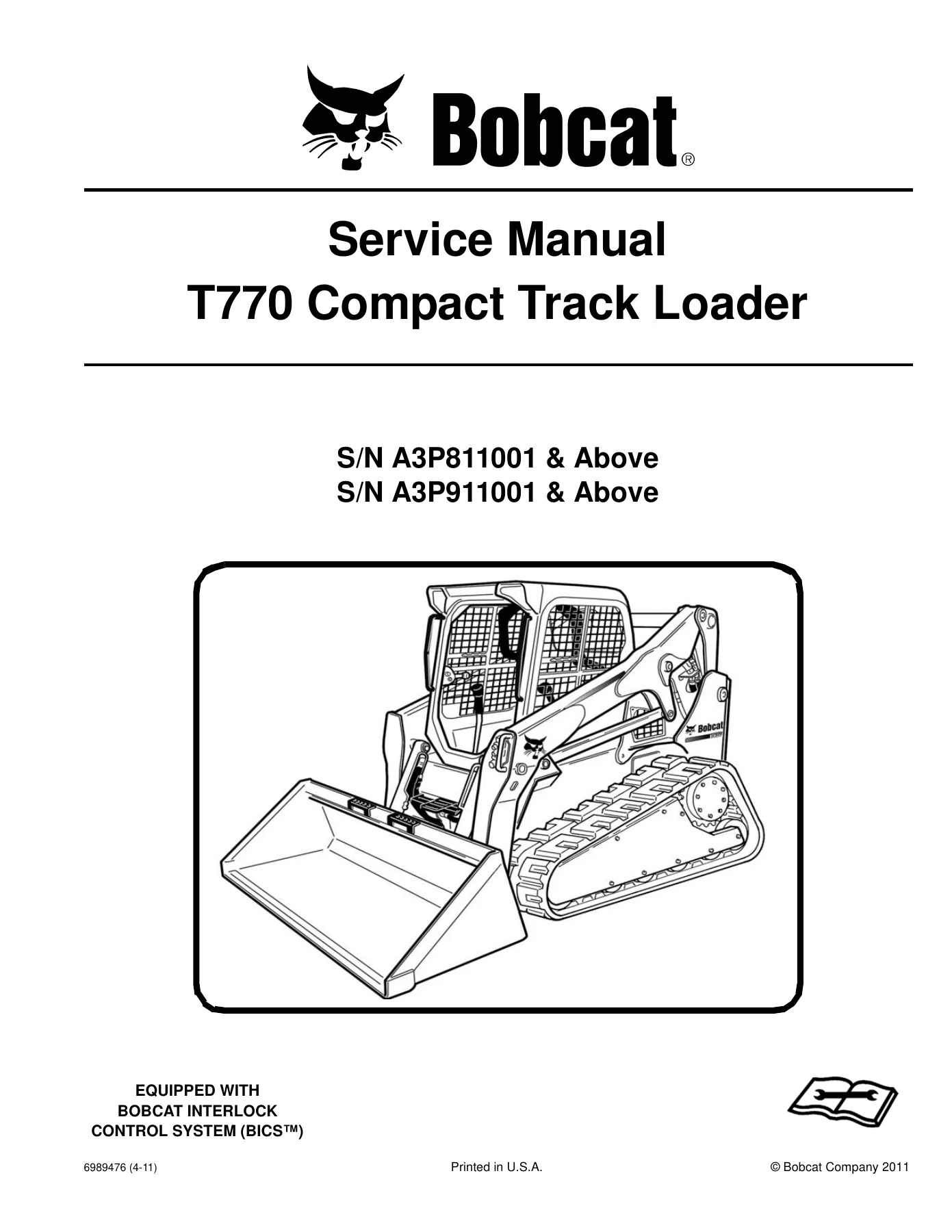
Bobcat T770 Compact Track Loader Service Manual S/N A3P811001 & A3P911001 Above

Original price was: $36.95.Current price is: $21.95.

918-page Bobcat T770 Compact Track Loader service manual 6989476 (4-11) covering S/N A3P811001 & above and S/N A3P911001 & above. Shop procedures for hydraulics, hydrostatics, tracks, BICS, Kubota V3800-DI-TE3 engine, HVAC, and specs.

Instant PDF Download
Available immediately
💾
Save to Your Device
Download & keep forever
🛡️
Antivirus Scanned
100% virus-free
🌍
Trusted Worldwide
175,000+ customers

Description

Bobcat T770 Compact Track Loader Service Manual S/N A3P811001 & A3P911001 Above

This Bobcat T770 Compact Track Loader Service Manual S/N A3P811001 & A3P911001 Above is written for the loader mechanic who has to keep a T770 compact track loader in the shop, not just on a daily walk-around. Publication 6989476 (4-11) from Bobcat Company (2011) walks through lifting and blocking, lift-arm support, cab raise/lower, hydraulic and hydrostatic teardown, track and undercarriage work, electrical analysis including BICS™, Kubota V3800-DI-TE3 engine service, and HVAC recharge. Serial coverage printed on the title page is S/N A3P811001 & Above and S/N A3P911001 & Above, with BICS™ as standard equipment.

File Details

  • Manual type: Service Manual
  • Brand / model: Bobcat T770 Compact Track Loader
  • Serial ranges: S/N A3P811001 & Above; S/N A3P911001 & Above
  • Language: English
  • Page count: 918
  • File format: PDF
  • Document number: 6989476 (4-11)
  • Copyright: Bobcat Company 2011

Machine And Engine Scope

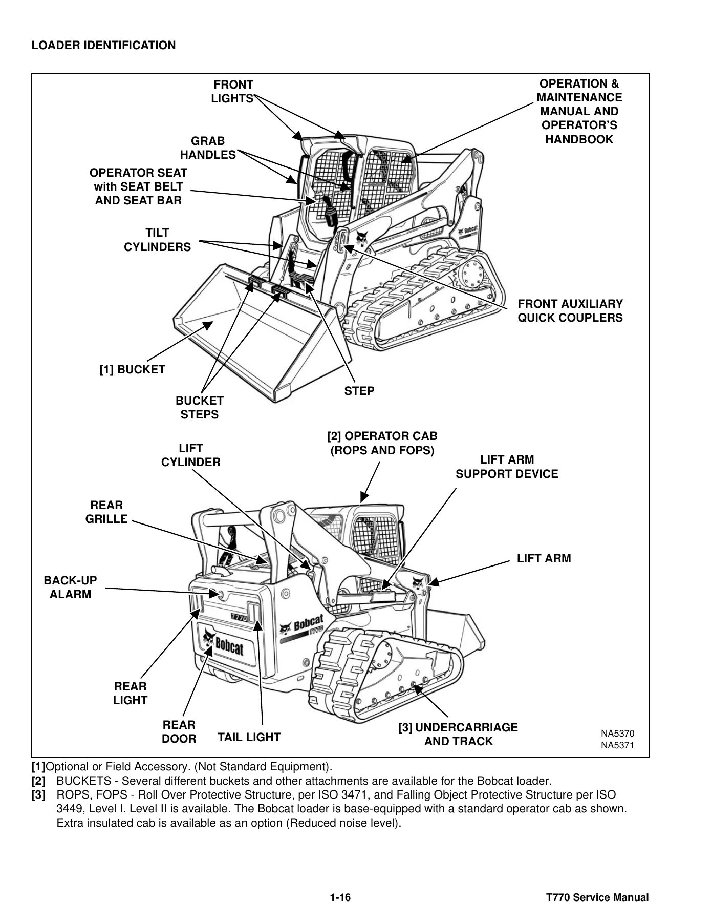
The T770 in this book is a compact track loader with a ROPS/FOPS operator cab (ISO 3471 rollover protection and ISO 3449 falling-object protection, Level I standard, Level II available). Loader identification plates and the engine serial stamp sit on the frame exterior and on the engine above the oil filter. The powerplant called out in both the engine chapter and the specification tables is a Kubota V3800-DI-TE3 Tier 3 turbo-diesel: four cylinders, 3769 cm³ (230 in³), 100 mm / 120 mm bore and stroke, liquid-cooled, gear-pump lubrication, dry dual-element air cleaner, open crankcase ventilation, and an automatically timed air-intake heater. Printed outputs are 65,6 kW (88.0 hp) net ISO 9249 / SAE J1349, 67,6 kW (90.6 hp) ISO 14396 gross, and 68,6 kW (92.0 hp) SAE J1995 gross, all at 2400 rpm, with net torque 310,3 N·m (228.8 ft-lb) at 1600 rpm. Idle windows are 1250–1400 rpm low and 2525–2650 rpm high.

Drive is fully hydrostatic rubber-track: infinitely variable tandem piston pumps feeding two reversing hydrostatic motors, with grease-cylinder and spring track tension. Control layouts covered include two hand steering levers or optional joysticks, foot-pedal lift/tilt or optional Advanced Control System (ACS) and Selectable Joystick Controls (SJC), front auxiliary on the right-hand lever, optional rear auxiliary, key start or optional keyless / Deluxe Instrumentation Panel, and a spring-applied, pressure-released multi-disk parking brake. Hydraulic pump capacity is listed at 87,1 L/min (23.0 U.S. gpm) standard and 138,2 L/min (36.5 U.S. gpm) high-flow, with system relief at the quick couplers of 23,8–24,5 MPa (3450–3550 psi).

Chapters Covered

  • Safety & Maintenance — lifting and blocking; lift arm support device; operator cab raise/lower, door sensor, Special Applications Kit, Forestry Door and Window Kit; trailer transport and towing; remote start tools MEL1563 and 7003031; service schedule; air cleaner; cooling system; fuel system and biodiesel notes; engine lubrication; hydraulic/hydrostatic fluid and filters; Bob-Tach hand-lever and power; lubrication points; spark arrester muffler; pivot pins; storage; emergency exit; seat belt
  • Hydraulic System — symbol glossary and troubleshooting; lift, tilt, and Bob-Tach cylinders (test, R&I, parts ID, disassembly/assembly); main relief valve test and adjust; control valve, accumulator, lift-arm bypass; hydraulic pump standard and high-flow direct pump tests; power Bob-Tach block
  • Hydrostatic System — system description and troubleshooting; single-speed and two-speed drive motors (oil service, R&I, disassembly); charge pressure test and adjust; hydrostatic pump and SJC pump (startup, relief/bypass valves, disassembly, mechanical and controller neutral); drive belt and drain manifold
  • Drive System — parking brake; track tension and replacement for solid-mounted and roller-suspension undercarriage; sprockets, rollers, idlers; track damage identification
  • Mainframe — seat bar; operator cab hardware; lift arms and cylinders mounts; Bob-Tach; rear door and grille; fuel tank; access panels; control linkages and pintle/neutral adjustment; windows, headliner, and related cab parts
  • Electrical System & Analysis — system information, fuses, battery and jump start, alternator and starter tests; instrument panels and Deluxe Instrumentation; service codes; BICS™ inspection (seat bar, traction lock, lift-arm bypass, auxiliary deactivation); ACS/SJC calibration and actuator tests; flywheel rpm sensor; password lockout; back-up alarm
  • Engine Service — engine information, specs, torque, troubleshooting, removal/installation and mounts, compression check; speed control (standard and SJC); muffler and air cleaner housing; radiator, hydraulic fan, water pump, thermostat; oil pan, oil pump, oil pressure test; fuel shutoff solenoid, injection pump timing, injectors and nozzle tests; cylinder head, valves, glow plugs; pistons, rods, crankshaft; camshaft and timing gears; turbocharger; flywheel and housing; EGR cold/hot tests
  • Heating, Ventilation and Air Conditioning (HVAC) — refrigerant flow and components; filters, compressor belt, condenser, evaporator/heater coil; pressure and electrical troubleshooting; R134a reclaim and charge; compressor, condenser, receiver/drier
  • Specifications — T770 machine dimensions, performance by undercarriage type, engine, drive, controls, hydraulics, electrical, capacities, tracks and ground pressure; SAE and metric bolt torque; hydraulic connection specs; hydraulic/hydrostatic fluid viscosity; conversion charts
  • Alphabetical Index

Complete PDF Bookmark Tree

Complete Bookmarks

The complete bookmarks in the “Bobcat T770 Compact Track Loader Service Manual S/N A3P811001 & A3P911001 Above” are as follows:

MAINTENANCE SAFETYp. 3
CONTENTSp. 5
FOREWORDp. 7
FOREWORDp. 9
SAFETY INSTRUCTIONSp. 12
FIRE PREVENTIONp. 14
Maintenancep. 14
Operationp. 14
Electricalp. 14
Hydraulic Systemp. 14
Fuelingp. 14
Startingp. 14
Spark Arrestor Exhaust Systemp. 14
Welding And Grindingp. 15
Fire Extinguishersp. 15
SERIAL NUMBER LOCATIONSp. 16
Loader Serial Numberp. 16
Engine Serial Numberp. 16
DELIVERY REPORTp. 17
LOADER IDENTIFICATIONp. 18
SAFETY & MAINTENANCEp. 19
LIFTING AND BLOCKING THE LOADERp. 21
Procedurep. 21
LIFT ARM SUPPORT DEVICEp. 23
Installingp. 23
Removingp. 24
OPERATOR CABp. 25
Descriptionp. 25
Raisingp. 26
Loweringp. 27
Cab Door Sensorp. 28
Special Applications Kitp. 28
Special Applications Kit Inspection And Maintenancep. 28
Forestry Door And Window Kitp. 29
Forestry Door And Window Kit Inspection And Maintenancep. 29
TRANSPORTING THE LOADER ON A TRAILERp. 31
Loading And Unloadingp. 31
Fasteningp. 31
TOWING THE LOADERp. 33
Procedurep. 33
REMOTE START TOOL KIT-MEL1563p. 35
Remote Start Tool – MEL1563p. 35
Service Tool Harness Control – MEL1565p. 36
Service Tool Harness Communicator – MEL1566p. 37
Remote Start Procedurep. 37
REMOTE START TOOL (SERVICE TOOL) KIT – 7003031p. 41
Descriptionp. 41
Remote Start Tool (Service Tool) – 7003030p. 42
Loader Service Tool Harness – 6689747p. 43
Computer Service Tool Harness – 6689746p. 44
Remote Start Procedurep. 45
SERVICE SCHEDULEp. 49
Chartp. 49
AIR CLEANER SERVICEp. 51
Replacing Filter Elementsp. 51
ENGINE COOLING SYSTEMp. 53
Maintenance Platformp. 53
Cleaningp. 53
Checking Levelp. 55
Removing And Replacing Coolantp. 56
FUEL SYSTEMp. 57
Fuel Specificationsp. 57
Biodiesel Blend Fuelp. 57
Filling The Fuel Tankp. 58
Fuel Filterp. 59
Removing Air From The Fuel Systemp. 59
ENGINE LUBRICATION SYSTEMp. 61
Checking And Adding Engine Oilp. 61
Engine Oil Chartp. 61
Removing And Replacing Oil And Filterp. 62
HYDRAULIC / HYDROSTATIC SYSTEMp. 63
Checking And Adding Fluidp. 63
Hydraulic / Hydrostatic Fluid Chartp. 63
Removing And Replacing Hydraulic Fluidp. 64
Removing And Replacing Hydraulic / Hydrostatic Filterp. 66
Removing And Replacing Hydraulic Charge Filterp. 67
Breather Capp. 68
BOB-TACH (HAND LEVER)p. 69
Inspection And Maintenancep. 69
BOB-TACH (POWER)p. 71
Inspection And Maintenancep. 71
LUBRICATING THE LOADERp. 73
Lubrication Locationsp. 73
SPARK ARRESTER MUFFLERp. 77
Cleaning Procedurep. 77
PIVOT PINSp. 79
Inspection And Maintenancep. 79
LOADER STORAGE AND RETURN TO SERVICEp. 81
Storagep. 81
Return To Servicep. 81
STOPPING THE ENGINE AND LEAVING THE LOADERp. 83
Procedurep. 83
EMERGENCY EXITp. 85
External Accessp. 85
Rear Windowp. 85
Front Doorp. 85
SEAT BELTp. 87
Inspection And Maintenancep. 87
HYDRAULIC SYSTEMp. 89
HYDRAULIC / HYDROSTATIC SCHEMATICSp. 93
HYDRAULIC SYSTEM INFORMATIONp. 101
Glossary Of Hydraulic / Hydrostatic Symbolsp. 101
Troubleshootingp. 105
CYLINDER (LIFT)p. 107
Testingp. 107
Removal And Installationp. 108
Parts Identificationp. 112
Disassemblyp. 113
Assemblyp. 114
CYLINDER (TILT)p. 117
Testingp. 117
Removal And Installationp. 118
Base End Pivot Pin Removal And Installationp. 120
Parts Identificationp. 121
Disassemblyp. 122
Assemblyp. 124
CYLINDER (BOB-TACH)p. 127
Testingp. 127
Removal And Installationp. 128
Parts Identificationp. 129
Disassemblyp. 130
Assemblyp. 131
MAIN RELIEF VALVEp. 135
Descriptionp. 135
Testingp. 136
Adjustingp. 138
Removal And Installationp. 139
HYDRAULIC CONTROL VALVE (STANDARD)p. 141
Descriptionp. 141
Removal And Installationp. 142
Mount Bracket Removal And Installationp. 145
Identification Chartp. 146
Lift Load Check Valve Removal And Installationp. 147
Load Check Valve Removal And Installation (Tilt And Auxiliary)p. 148
Anti-Cavitation Valve Removal And Installation (Lift, Rod End)p. 149
Port Relief / Anti-Cavitation Valve Removal And Installation (Lift, Base End)p. 149
Port Relief / Anti-Cavitation Valve Removal And Installation (Tilt, Base End)p. 150
Port Relief / Anti-Cavitation Valve Removal And Installation (Tilt, Rod End)p. 150
Port Relief Valve Removal And Installationp. 151
Plug Removal And Installationp. 152
Rubber Boot Removal And Installationp. 153
End Cap Block Removal And Installationp. 154
Lift Spool And Detent Removal And Installationp. 155
Tilt Spool Removal And Installationp. 165
Auxiliary Spool Removal And Installationp. 167
Auxiliary Solenoid Removal And Installationp. 169
Solenoid Removal And Installationp. 170
Lock Valve Removal And Installationp. 171
Lift Arm Bypass Orifice Removal And Installationp. 173
Main Relief Valve Removal And Installationp. 173
Check Valve Removal And Installationp. 174
HYDRAULIC CONTROL VALVE (ACS) OR (SJC)p. 175
Descriptionp. 175
Removal And Installationp. 175
Actuator Removal And Installation (In Loader)p. 179
Actuator Removal And Installation (Out Of Loader)p. 181
Identification Chartp. 184
Mount Bracket Removal And Installationp. 185
Lift Load Check Valve Removal And Installationp. 185
Load Check Valve Removal And Installation (Tilt And Auxiliary)p. 186
Anti-Cavitation Valve Removal And Installation (Lift, Rod End)p. 187
Port Relief / Anti-Cavitation Valve Removal And Installation (Lift, Base End)p. 187
Port Relief / Anti-Cavitation Valve Removal And Installation (Tilt, Base End)p. 188
Port Relief / Anti-Cavitation Valve Removal And Installation (Tilt, Rod End)p. 188
Port Relief Valve Removal And Installationp. 189
Plug Removal And Installationp. 190
End Cap Block Removal And Installationp. 191
Lift Spool Removal And Installationp. 191
Lift Spool Disassembly And Assemblyp. 193
Tilt Spool Removal And Installationp. 195
Auxiliary Spool Removal And Installationp. 197
Auxiliary Solenoid Removal And Installationp. 198
Solenoid Removal And Installationp. 199
Lock Valve Removal And Installationp. 200
Lift Arm Bypass Orifice Removal And Installationp. 201
Main Relief Valve Removal And Installationp. 201
Check Valve Removal And Installationp. 202
LIFT ARM BYPASS CONTROL VALVEp. 203
Descriptionp. 203
Testingp. 203
Removal And Installationp. 204
Bracket Removal And Installationp. 205
Disassembly And Assemblyp. 205
HYDRAULIC PUMPp. 207
Descriptionp. 207
Pump Test At Quick Couplersp. 207
Direct Pump Test (Standard Section)p. 208
Direct Pump Test (Charge Section)p. 210
Removal And Installationp. 212
Hydraulic Pump Startupp. 213
Parts Identificationp. 214
Disassembly And Assemblyp. 215
HYDRAULIC PUMP (HIGH FLOW)p. 217
Descriptionp. 217
Pump Test At Quick Couplersp. 217
Direct Pump Test (Standard Section)p. 218
Direct Pump Test (Charge Section)p. 219
Direct Pump Test (High Flow Section)p. 221
High Flow Relief Valve Adjustmentp. 223
High Flow Relief Valve Removal And Installationp. 224
Solenoid Removal And Installationp. 225
Removal And Installationp. 226
Hydraulic Pump Startupp. 228
Parts Identificationp. 229
Disassembly And Assemblyp. 230
HYDRAULIC / HYDROSTATIC FILTERSp. 231
Descriptionp. 231
Housing Removal And Installationp. 231
HYDRAULIC FLUID RESERVOIRp. 233
Descriptionp. 233
Removal And Installationp. 233
Hydraulic Fluid Screenp. 234
OIL COOLERp. 235
Descriptionp. 235
Removal And Installationp. 235
BUCKET POSITION VALVEp. 237
Descriptionp. 237
Solenoid Removal And Installationp. 237
Solenoid Testingp. 238
Removal And Installationp. 238
Disassembly And Assemblyp. 240
REAR AUXILIARY DIVERTER VALVEp. 241
Descriptionp. 241
Solenoid Testingp. 241
Removal And Installationp. 242
Disassembly And Assemblyp. 243
BOB-TACH (POWER) BLOCKp. 249
Descriptionp. 249
Removal And Installationp. 249
Disassembly And Assemblyp. 251
FRONT AUXILIARY HYDRAULIC COUPLER BLOCKp. 261
Descriptionp. 261
Removal And Installationp. 261
Disassembly And Assemblyp. 261
HYDROSTATIC SYSTEMp. 263
HYDROSTATIC SYSTEM INFORMATIONp. 265
Descriptionp. 265
Troubleshootingp. 266
HYDROSTATIC DRIVE MOTORp. 267
Descriptionp. 267
Removing And Replacing Oilp. 267
Removal And Installationp. 268
Parts Identificationp. 270
Disassembly And Assemblyp. 272
HYDROSTATIC DRIVE MOTOR (TWO SPEED)p. 285
Descriptionp. 285
Removing And Replacing Oilp. 285
Removal And Installationp. 286
Parts Identificationp. 288
Disassembly And Assemblyp. 290
CHARGE PRESSUREp. 303
Descriptionp. 303
Testingp. 303
Sender Removal And Installationp. 305
Adjustingp. 306
HYDROSTATIC PUMPp. 309
Descriptionp. 309
Removal And Installationp. 310
Hydrostatic Pump Startupp. 311
Replenishing / High Pressure Relief Valve Removal And Installationp. 312
Parts Identification (Left Half)p. 313
Parts Identification (Right Half)p. 314
Disassemblyp. 315
Assemblyp. 322
HYDROSTATIC PUMP (SJC)p. 329
Descriptionp. 329
Hydraulic Controller Removal And Installationp. 330
Removal And Installationp. 332
Hydrostatic Pump Start Upp. 334
Parts Identificationp. 335
High Pressure Relief And Bypass Valvep. 336
Charge Relief Valvep. 337
Disassemblyp. 338
Inspectionp. 347
Assemblyp. 351
Mechanical Neutral Adjustmentp. 361
Hydraulic Controller Neutral Adjustmentp. 364
DRIVE BELTp. 367
Belt Adjustmentp. 367
Belt Replacementp. 367
Stop Adjustmentp. 369
Tensioner Pulley Removal And Installationp. 370
Tensioner Pulley Disassembly And Assemblyp. 370
DRAIN MANIFOLDp. 373
Descriptionp. 373
Drain Manifold Removal And Installationp. 373
DRIVE SYSTEMp. 375
BRAKEp. 377
Descriptionp. 377
Block Removal And Installationp. 377
Block Disassembly And Assemblyp. 378
TRACK UNDERCARRIAGE COMPONENTS (SOLID- MOUNTED)p. 381
Descriptionp. 381
Checking Tensionp. 382
Adjusting Tensionp. 383
Track Removal And Installationp. 384
Idler (Front) Removal And Installationp. 386
Track Tensioner Disassembly And Assemblyp. 389
Idler (Rear) Removal And Installationp. 391
Roller Removal And Installationp. 391
Sprocket Removal And Installation (Single Speed)p. 392
Sprocket Removal And Installation (Two Speed)p. 392
Track Housing Removal And Installationp. 393
TRACK UNDERCARRIAGE COMPONENTS (ROLLER SUSPENSION)p. 395
Descriptionp. 395
Checking Tensionp. 396
Adjusting Tensionp. 397
Track Removal And Installationp. 398
Idler (Front) Removal And Installationp. 400
Track Tensioner Disassembly And Assemblyp. 403
Idler (Rear) Removal And Installationp. 405
Roller Removal And Installationp. 405
Leaf Spring Removal And Installationp. 406
Sprocket Removal And Installationp. 407
Track Housing Removal And Installationp. 408
TRACK MAINTENANCEp. 409
Track Damage Identificationp. 409
MAINFRAMEp. 421
SEAT BARp. 425
Descriptionp. 425
Removal And Installationp. 425
Disassembly And Assemblyp. 426
Compression Spring Disassembly And Assemblyp. 427
OPERATOR CABp. 429
Gas Spring Removal And Installationp. 429
Gas Spring Bracket Disassembly And Assemblyp. 430
Removal And Installationp. 430
OPERATOR SEAT (SUSPENSION)p. 433
Removal And Installationp. 433
Slide Rail Removal And Installationp. 433
Seat Belt Removal And Installationp. 434
Lower Cushion Removalp. 434
Lower Cushion Installationp. 435
Back Cushion Removal And Installationp. 435
Shock Removal And Installationp. 436
3-Point Seat Belt Removal And Installationp. 436
BOB-TACH (HAND LEVER)p. 439
Descriptionp. 439
Removal And Installationp. 439
Lever And Wedge Disassembly And Assemblyp. 441
Pivot Pin Bushing And Seal Removal And Installationp. 443
BOB-TACH (POWER)p. 445
Descriptionp. 445
Removal And Installationp. 445
Lever And Wedge Disassembly And Assemblyp. 448
Pivot Pin Bushing And Seal Removal And Installationp. 449
LIFT ARMSp. 451
Stabilizer Bar Removal And Installationp. 451
Link Removal And Installationp. 452
Removal And Installationp. 453
REAR GRILLEp. 457
Removal And Installationp. 457
REAR DOOR (TAILGATE)p. 459
Removal And Installationp. 459
Striker Removal And Installationp. 460
Striker Disassembly And Assemblyp. 460
Striker (Adjusting)p. 460
Latch Removal And Installationp. 461
FUEL TANKp. 463
Removal And Installationp. 463
Fuel Level Sender Removal And Installationp. 465
Fuel Fill Screen Removal And Installationp. 465
CONTROL PEDALS AND LINKAGESp. 467
Descriptionp. 467
Pedal Removal And Installationp. 467
Linkage Removal And Installationp. 468
Pedal (Adjusting)p. 469
Floor Pan Removal And Installationp. 470
CONTROL PEDALS AND LINKAGES (ACS)p. 471
Descriptionp. 471
Pedal Removal And Installationp. 471
Linkage Removal And Installationp. 472
Pedal (Adjusting)p. 472
Floor Pan Removal And Installationp. 473
CONTROL PANELp. 475
Descriptionp. 475
Removal And Installationp. 476
Disassembly And Assemblyp. 477
Linkage Removal And Installationp. 479
Pintle Arm Disassembly And Assemblyp. 483
Linkage Neutral (Adjusting)p. 484
Linkage Travel (Adjusting)p. 488
Shock Removal And Installationp. 492
CONTROL PANEL (SJC)p. 493
Descriptionp. 493
Removal And Installationp. 493
CONTROL HANDLE / LEVERp. 495
Descriptionp. 495
Lever Removal And Installationp. 495
Boot Removal And Installationp. 496
CONTROL HANDLE / LEVER (ACS)p. 497
Descriptionp. 497
Handle Sensor Removal And Installationp. 497
Handle Removal And Installationp. 500
Handle Disassembly And Assemblyp. 501
Lever Removal And Installationp. 501
Boot Removal And Installationp. 502
CONTROL HANDLE / LEVER (SJC)p. 503
Descriptionp. 503
Joystick Testingp. 503
Joystick Removal And Installationp. 504
ACCESS PANEL (INSIDE)p. 505
Removal And Installation (Left)p. 505
Removal And Installation (Right)p. 505
ACCESS PANEL (INSIDE) (SJC)p. 507
Removal And Installation (Left)p. 507
Removal And Installation (Right)p. 507
WINDOW (REAR)p. 509
Removal And Installationp. 509
Disassembly And Assemblyp. 509
WINDOW (TOP)p. 511
Removal And Installationp. 511
WINDOW (SIDE)p. 513
Removal And Installationp. 513
CAB DOORp. 515
Descriptionp. 515
Removal And Installationp. 515
Disassembly And Assemblyp. 516
Aligningp. 517
Adjustingp. 518
Checking Operationp. 518
ARMRESTp. 519
Descriptionp. 519
Removal And Installationp. 520
Disassembly And Assemblyp. 521
LEFT SIDE LOWER PANELp. 523
Removal And Installationp. 523
Disassembly And Assemblyp. 525
RIGHT SIDE LOWER PANELp. 527
Removal And Installationp. 527
Disassembly And Assemblyp. 528
HEADLINERp. 531
Removal And Installationp. 531
ELECTRICAL SYSTEM & ANALYSISp. 533
ELECTRICAL SCHEMATICSp. 537
ELECTRICAL SYSTEM INFORMATIONp. 565
Glossary Of Electrical Symbolsp. 565
Standard Cab Harness Connectorsp. 568
Deluxe Cab Harness Connectorsp. 569
Mainframe Harness Connectorsp. 570
Descriptionp. 571
Troubleshootingp. 572
Fuse And Relay Location / Identificationp. 573
Solenoid Testingp. 575
BATTERYp. 577
Removal And Installationp. 577
Servicingp. 578
Using A Booster Battery (Jump Starting)p. 579
ALTERNATORp. 581
Belt Adjustmentp. 581
Belt Replacementp. 581
Charging System Inspectionp. 582
Alternator Voltage Testingp. 583
Low Voltage Testingp. 583
High Voltage Testingp. 584
Removal And Installationp. 585
Parts Identificationp. 586
STARTERp. 587
Testingp. 587
Removal And Installationp. 587
Parts Identificationp. 588
INSTRUMENT PANELSp. 589
Left Panelp. 589
Display Screenp. 591
Right Panel (Standard Key Panel)p. 592
Right Panel (Keyless Start Panel)p. 593
Right Panel (Deluxe Instrumentation Panel)p. 594
Left Switch Panelp. 596
Right Switch Panelp. 596
Left Panel Removal And Installationp. 597
Right Panel (Standard Key Panel) Removal And Installationp. 597
Right Panel (Keyless Start Panel) Removal And Installationp. 598
Right Panel (Deluxe Instrumentation Panel) Removal And Installationp. 598
Key Switch Disassembly And Assemblyp. 599
Alarm Disassembly And Assemblyp. 599
Left Switch Panel Removal And Installationp. 600
Right Switch Panel Removal And Installationp. 600
LIGHTSp. 601
Front Removal And Installationp. 601
Rear Removal And Installationp. 602
Cab Light Removal And Installationp. 602
BOBCAT CONTROLLERS (GATEWAY AND AUXILIARY)p. 603
Descriptionp. 603
Connector Identificationp. 604
Removal And Installationp. 610
BOBCAT CONTROLLER (ACS)p. 611
Descriptionp. 611
Connector And Wire Identificationp. 612
Removal And Installationp. 613
BOBCAT CONTROLLER (SJC) (DRIVE)p. 615
Descriptionp. 615
Connector Identificationp. 616
Removal And Installationp. 618
SPEED SENSORS (SJC)p. 619
Descriptionp. 619
Testingp. 619
Removal And Installationp. 620
DIAGNOSTIC SERVICE CODESp. 623
Viewing Service Codesp. 623
Service Codes Listp. 624
BOBCAT INTERLOCK CONTROL SYSTEM (BICS™)p. 629
Descriptionp. 629
Inspecting The BICS™ (Engine STOPPED – Key ON)p. 630
Inspecting Deactivation Of The Auxiliary Hydraulics System (Engine STOPPED – Key ON)p. 630
Inspecting The Seat Bar Sensor (Engine RUNNING)p. 630
Inspecting The Traction Lock (Engine RUNNING)p. 630
Inspecting The Lift Arm Bypass Controlp. 630
Inspecting Deactivation Of Lift And Tilt Functions (ACS And SJC)p. 630
Troubleshootingp. 631
SEAT BAR SENSORp. 633
Descriptionp. 633
Troubleshootingp. 633
Testingp. 634
Removal And Installationp. 635
Bobcat Interlock Control System (BICS™) Circuit Testp. 638
TRACTION LOCKp. 641
Descriptionp. 641
Troubleshootingp. 642
Inspectingp. 643
CONTROL SYSTEM (ACS)p. 645
Descriptionp. 645
Troubleshootingp. 646
Handle Sensor Connector Disassembly And Assemblyp. 647
Switch Handle Removalp. 648
Switch Handle Installationp. 650
Actuator Connector Disassembly And Assemblyp. 653
Handle Lock Solenoid Removal And Installationp. 654
Handle Lock Solenoid Disassembly And Assemblyp. 654
Foot Sensor Removal And Installationp. 655
Foot Sensor Disassembly And Assemblyp. 656
Foot Sensor Lock Solenoid Removal And Installationp. 656
ELECTRICAL / HYDRAULIC CONTROLSp. 657
Identification Chartp. 657
Descriptionp. 658
Identification Chart ACD Group 0p. 659
Identification Chart ACD Group 1p. 660
Identification Chart ACD Group 2p. 661
Identification Chart ACD Group 3p. 662
ELECTRICAL / HYDRAULIC CONTROLS (ACS)p. 663
Identification Chartp. 663
Descriptionp. 664
Identification Chart ACD Group 0p. 665
Identification Chart ACD Group 1p. 666
Identification Chart ACD Group 2p. 667
Identification Chart ACD Group 3p. 668
ELECTRICAL / HYDRAULIC CONTROLS (SJC)p. 669
Identification Chartp. 669
Descriptionp. 670
Identification Chart ACD Group 0p. 671
Identification Chart ACD Group 1p. 672
Identification Chart ACD Group 2p. 673
Identification Chart ACD Group 3p. 674
SERVICE PC (LAPTOP COMPUTER)p. 675
Connecting Remote Start Toolp. 675
Connecting Remote Start Tool (Service Tool)p. 675
CALIBRATIONp. 677
Descriptionp. 677
Actuator Testingp. 677
Lift And Tilt Calibration (SJC)p. 680
Hydrostatic Pump Calibration (SJC)p. 682
Lift And Tilt Calibration (ACS)p. 687
STEERING DRIFT COMPENSATIONp. 689
Descriptionp. 689
Operationp. 689
FLYWHEEL RPM SENSORp. 691
Descriptionp. 691
Adjustmentp. 692
CONTROL PANEL SETUPp. 693
Right Panel Setup (Deluxe Instrumentation Panel)p. 693
PASSWORD SETUP (DELUXE INSTRUMENTATION PANEL)p. 695
Password Descriptionp. 695
Changing The Owner Passwordp. 695
Changing The User Passwordsp. 696
Password Lockout Featurep. 696
PASSWORD SETUP (KEYLESS START PANEL)p. 697
Password Descriptionp. 697
Changing The Owner Passwordp. 697
Password Lockout Featurep. 697
MAINTENANCE CLOCKp. 699
Descriptionp. 699
Setupp. 700
Resetp. 703
BACK-UP ALARM SYSTEMp. 705
Descriptionp. 705
Inspectingp. 705
Adjusting Switch Positionp. 706
Troubleshooting (Standard And ACS)p. 707
Troubleshooting (Joystick)p. 708
Alarm Removal And Installationp. 709
Switch Removal And Installationp. 709
FRONT HORNp. 711
Removal And Installationp. 711
ENGINE SERVICEp. 713
ENGINE INFORMATIONp. 717
Descriptionp. 717
Specificationsp. 718
Torque Valuesp. 721
Troubleshootingp. 721
Engine Removal And Installationp. 723
Engine Mount Replacementp. 730
Compression – Checkingp. 731
ENGINE SPEED CONTROLp. 733
Removal And Installationp. 733
Disassembly And Assemblyp. 733
Cable Removal And Installationp. 734
ENGINE SPEED CONTROL (SJC)p. 735
Removal And Installationp. 735
Disassembly And Assemblyp. 736
MUFFLERp. 739
Removal And Installationp. 739
AIR CLEANERp. 741
Housing Removal And Installationp. 741
ENGINE COOLING SYSTEMp. 743
Radiator Removal And Installationp. 743
Hydraulic Fan Descriptionp. 745
Hydraulic Fan Disassembly And Assemblyp. 746
Lower Fan Duct Removal And Installationp. 747
Blower Housing Removal And Installationp. 747
Hydraulic Fan Motor Assembly Removal And Installationp. 748
Fan Removal And Installationp. 748
Hydraulic Fan Motor Removal And Installationp. 749
Water Pump Removal And Installationp. 750
Water Pump Disassembly And Assemblyp. 750
Thermostat Housing Removal And Installationp. 751
Thermostat – Checkingp. 752
LUBRICATION SYSTEMp. 753
Oil Pan Removal And Installationp. 753
Oil Pump Removal And Installationp. 753
Relief Valve – Testingp. 754
Oil Pump Inspectionp. 754
Oil Filter Cooler Removal And Installationp. 755
Engine Oil Pressure – Testingp. 756
FUEL SYSTEMp. 757
Fuel Shutoff Solenoid – Checkingp. 757
Fuel Shutoff Solenoid Removal And Installationp. 757
Fuel Injection Pump Assembly Removalp. 758
Fuel Injection Pump Assembly Installationp. 762
Governor Housing Disassembly And Assemblyp. 764
Governor Disassembly And Assemblyp. 766
Fuel Camshaft Removal And Installationp. 768
Fuel Injection Pump Removalp. 770
Injection Pump – Timingp. 776
Fuel Injector Removal And Installationp. 780
Fuel Injector Nozzle Pressure – Checkingp. 781
Nozzle Spraying Conditionp. 782
Valve Seat Tightnessp. 782
CYLINDER HEADp. 783
Glow Plugs – Testingp. 783
Glow Plugs Removal And Installationp. 783
Valve Clearance Adjustmentp. 784
Valve Timing – Checkingp. 785
Cylinder Head Removal And Installationp. 786
Cylinder Head Disassembly And Assemblyp. 789
Cylinder Head – Servicingp. 789
Cylinder Head Top Clearancep. 790
Valve Guide – Checkingp. 790
Valve Guide Removal And Installationp. 791
Reconditioning The Valve And Valve Seatp. 791
Valve Springp. 793
Valve Tappetsp. 794
Rocker Arm And Shaft – Checkingp. 795
Bridge Arm And Bridge Arm Shaft – Checkingp. 795
Bridge Arm Shaft – Removal And Installationp. 796
Push Rod Alignment – Checkingp. 797
CRANKSHAFT AND PISTONSp. 799
Piston And Connecting Rod Removal And Installationp. 799
Piston And Connecting Rod – Servicingp. 800
Cylinder Bore – Checkingp. 803
Connecting Rod Alignmentp. 804
Crankshaft Gear Removal And Installationp. 804
Crankshaft And Bearings Removal And Installationp. 805
Crankshaft And Bearings – Servicingp. 807
CAMSHAFT AND TIMING GEARSp. 811
Timing Gearcase Cover Removalp. 811
Timing Gearcase Cover Installationp. 812
Timing Gears Backlash – Checkingp. 815
Idler Gear And Camshaft Removal And Installationp. 815
Camshaft – Servicingp. 816
Idler Gear And Shaft – Servicingp. 817
TURBOCHARGERp. 819
Descriptionp. 819
Testingp. 819
Removal And Installationp. 820
FLYWHEEL AND HOUSINGp. 823
Flywheel Removal And Installationp. 823
Ring Gear Removal And Installationp. 825
Housing Removal And Installationp. 825
EXHAUST GAS RECIRCULATION (EGR) SYSTEMp. 827
Descriptionp. 827
Testingp. 828
Removal And Installationp. 831
Disassembly And Assemblyp. 832
HEATING, VENTILATION AND AIR CONDITIONING (HVAC)p. 833
AIR CONDITIONING SYSTEM FLOWp. 835
Descriptionp. 835
Chartp. 836
Componentsp. 837
Safety Equipmentp. 840
REGULAR MAINTENANCEp. 841
Filtersp. 841
Compressor Drive Belt Adjustmentp. 842
Compressor Drive Belt Replacementp. 842
Condenserp. 842
Air Conditioning Lubricationp. 842
Air Conditioning Service Chartp. 843
Evaporator / Heater Coilp. 844
TROUBLESHOOTINGp. 845
Blower Motor Does Not Operatep. 845
Blower Motor Operates Normally, But Air Flow Is Insufficientp. 845
Insufficient Cooling Although Air Flow And Compressor Operation Are Normalp. 845
The Compressor Does Not Operate At All, Or Operates Improperlyp. 845
Gauge Pressure Related Troubleshootingp. 846
Troubleshooting Treep. 848
Temperature / Pressure Chartp. 851
Poor A/C Performancep. 853
HVAC Repair And Leaksp. 854
Electrical Systemp. 855
Engine Coolant Bypassing The Heater Valvep. 861
Heater Valve Not Opening Or Closingp. 862
SYSTEM CHARGING AND RECLAMATIONp. 863
Refrigerant Identificationp. 863
Reclamation And Charging With Recovery / Charging Unitp. 864
COMPRESSORp. 867
Removal And Installationp. 867
Oilp. 869
Oil Checkp. 870
CONDENSERp. 871
Removal And Installationp. 871
RECEIVER / DRIERp. 873
Receiver / Drier Removal And Installationp. 873
Pressure Relief Valve Removal And Installationp. 874
Pressure Switch Removal And Installationp. 875
Schrader® Valve Removal And Installationp. 876
EVAPORATOR / HEATER UNITp. 877
Removal And Installationp. 877
THERMOSTATp. 879
Descriptionp. 879
Removal And Installationp. 880
EXPANSION VALVEp. 881
Removal And Installationp. 881
EVAPORATOR COILp. 883
Removal And Installationp. 883
HEATER COILp. 885
Removal And Installationp. 885
BLOWER FANp. 887
Removal And Installationp. 887
Disassembly And Assemblyp. 887
HEATER VALVEp. 891
Removal And Installationp. 891
SPECIFICATIONSp. 893
(T770) LOADER SPECIFICATIONSp. 895
Machine Dimensionsp. 895
Performancep. 896
Enginep. 897
Drive Systemp. 897
Controlsp. 898
Hydraulic Systemp. 898
Electrical Systemp. 899
Capacitiesp. 899
Tracksp. 900
Ground Pressurep. 900
TORQUE SPECIFICATIONS FOR BOLTSp. 901
Torque For General SAE Boltsp. 901
Torque For General Metric Boltsp. 902
HYDRAULIC CONNECTION SPECIFICATIONSp. 903
Straight Thread O-ring Fittingp. 903
Flare Fittingp. 904
Tubelines And Hosesp. 904
HYDRAULIC / HYDROSTATIC FLUID SPECIFICATIONSp. 905
Specificationsp. 905
CONVERSIONSp. 907
Decimal And Millimeter Equivalent Chartp. 907
U.S. To Metric Conversion Chartp. 907
ALPHABETICAL INDEXp. 909
SERVICE MANUAL REVISIONp. 911
Revision No: T770 – 1p. 911
Revision No: T770 – 2p. 913
Revision No: T770 – 3p. 915
Revision No: T770 – 4p. 917

Taken together, the book is a shop-level sequence rather than an operator handbook. After service the foreword requires a return-to-service check that includes ROPS/FOPS condition, seat belt and seat bar, lift-arm support device, BICS™ function, leaks, fluid levels, track tension, and a full function run before the machine goes back to the owner.

Shop Work The Manual Actually Supports

Safety pages open with lift-and-block locations at the rear frame notches and front struts, plus the two-person method for installing the approved lift-arm support over a cylinder rod. Cab work covers nut-and-washer removal at the front corners, latch engagement when the cab is up, and 54–61 N·m (40–45 ft-lb) reinstall torque. Forestry and special-application polycarbonate doors have inspection, wash, and emergency-exit lever checks.

Hydraulic procedures go from leak-down tests on lift, tilt, and Bob-Tach cylinders through main-relief setting with a flow tester at 60°C (140°F) oil and high idle, then to gear-pump flow tests on both the standard section and the high-flow section. High-flow relief is adjusted against printed targets around 24,1 MPa (3500 psi) and 25,5 MPa (3700 psi). Hydrostatic work covers motor case oil with P/N 7003026 synthetic (180 mL / 6.1 U.S. fl oz each motor), disc-pack height 37.7 mm (1.48 in), charge-pressure sender service, pump-to-engine package R&I, and SJC controller bleed plus mechanical and hydraulic-controller neutral.

Track chapters separate solid-mounted and roller-suspension undercarriages, with tension measured so the track clears the floor by at least 76 mm (3 in) when the machine is blocked. Electrical analysis includes a 90-ampere belt-driven alternator, 12-volt 950 CCA battery, 3.0 kW starter, 100-ampere master fuse, connector pinouts, and a long service-code list (engine oil pressure, actuator circuits, display communication, and more). BICS™ inspection is written as a step sequence with the engine stopped and running so seat-bar, traction-lock, auxiliary, and lift-and-tilt lights can be verified before the machine is released.

Engine service is full in-frame and out-of-frame work: package removal with MEL1653-2 / MEL1686 / MEL1711 fixtures, mount torque 122–135 N·m (90–100 ft-lb), compression check after warm-up, injection-pump timing by fuel-rise at the number-four line, valve clearance by cylinder pairing, cylinder bore factory spec 94–94,022 mm with 94,15 mm allowable limit, connecting-rod bolt torque 69–73 N·m, flywheel bolts 98.1–107 N·m, and EGR surface-temperature checks below 55°C and above 70°C coolant. HVAC pages treat R134a identification, recovery/charge with a recycling unit, compressor PAG 100 oil fill 150–170 cc, and heater-valve coolant bypass tests.

Printed Capacities And Performance Figures

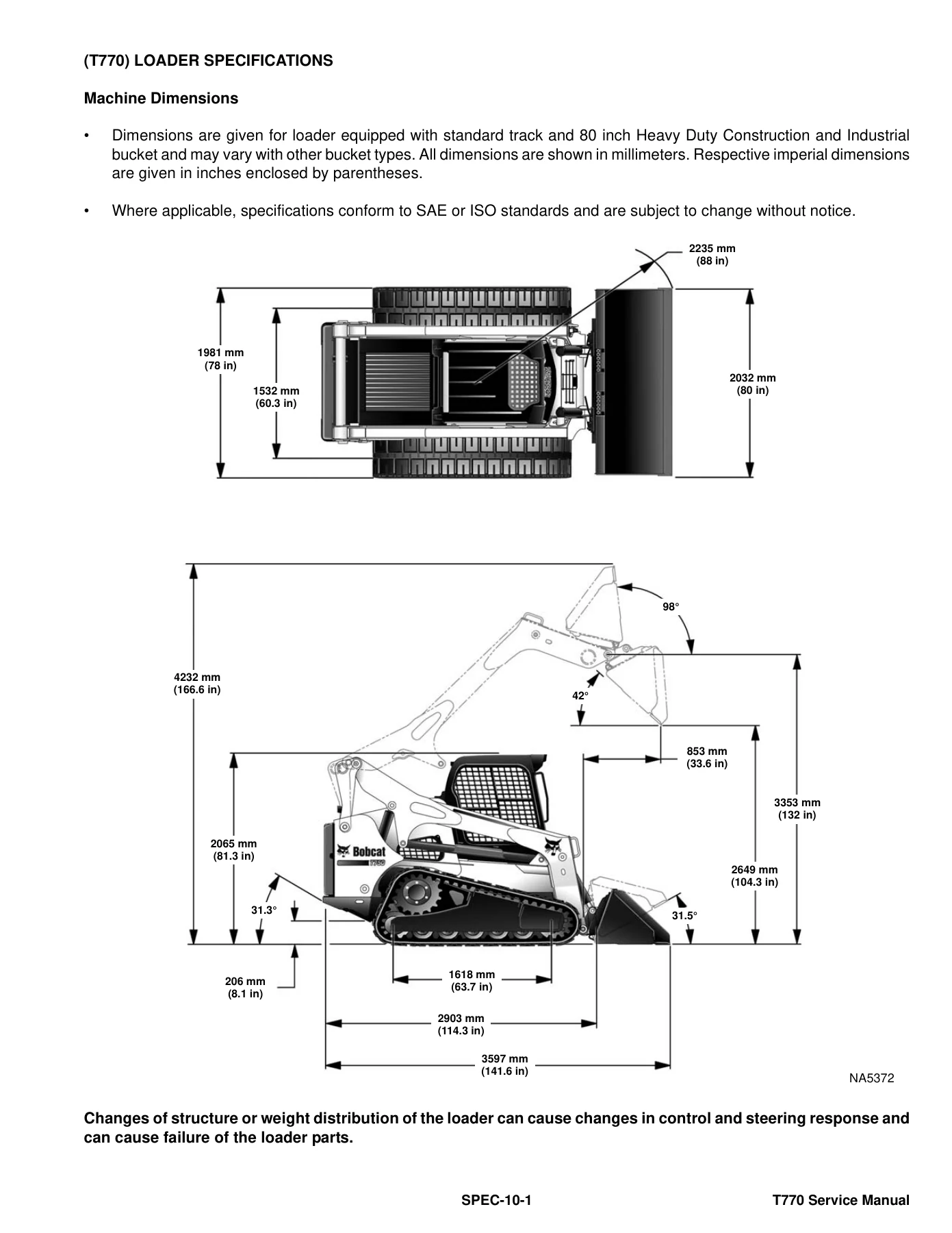
Specification tables at the back collect the numbers used throughout the procedures. Fuel tank 103,1 L (27.2 U.S. gal); engine oil with filter 11,4 L (12.0 qt); coolant 15,1 L (4.0 U.S. gal) with heater or 14,4 L (3.8 U.S. gal) without; hydraulic/hydrostatic reservoir 9,8 L (2.6 U.S. gal) and system 36,0 L (9.5 U.S. gal). Rated operating capacity varies by undercarriage: steel track 1361 kg (3000 lb), roller-suspension 1406 kg (3100 lb), solid-mounted 1576 kg (3475 lb), with optional frame counterweight kits listed. Travel speed is 0–10,6 km/h (0–6.6 mph) single-speed; two-speed option is 0–9,8 km/h low and 0–17,2 km/h high. Standard rubber track is 450 mm (17.7 in) C-pattern; optional narrow rubber 320 mm (12.6 in); steel 340 mm (13.38 in) triple grouser. Ground pressure examples include 0,029–0,030 MPa (4.2–4.4 psi) on 450 mm rubber depending on undercarriage.

IMAGES PREVIEW

Bobcat T770 Compact Track Loader Service Manual S/N A3P811001 & A3P911001 Above — PDF page 1 preview
Bobcat T770 Compact Track Loader Service Manual S/N A3P811001 & A3P911001 Above — PDF page 18 preview
Bobcat T770 Compact Track Loader Service Manual S/N A3P811001 & A3P911001 Above — PDF page 895 preview

Lift and tilt cylinders share a 76,2 mm (3.00 in) bore; lift rod 44,5 mm (1.75 in) and 660,2 mm stroke, tilt rod 41,3 mm (1.63 in) and 355,0 mm stroke. Function times printed are raise 4.03 s, lower 2.86 s, dump 2.34 s, rollback 2.05 s. Fluid specified is Bobcat Hydraulic/Hydrostatic fluid (P/N 6903117 / 6903118 / 6903119). Cooling system is factory-filled propylene glycol (purple); the text warns against mixing chemistries. Diesel is Grade No. 2 or No. 1; biodiesel is limited to B5 meeting ASTM D975 or EN590, with extra drain, hose, and storage cautions.

Who This Manual Is For

Use the Bobcat T770 Compact Track Loader Service Manual S/N A3P811001 & A3P911001 Above when the job is beyond the Operation & Maintenance Manual: pump and motor overhaul, injection timing, BICS™ diagnosis, ACS/SJC calibration after a controller swap, track frame work, or A/C reclaim. Remote start kits MEL1563 and 7003031 are documented so hydraulics and steering can be powered with the cab raised. Special tools named in procedures include those remote-start kits, engine lift attachments, and a recovery/charging machine for R134a. If a later or earlier serial uses different parts, the serial-number chapter tells you to confirm the plate before ordering.

Get The Manual And Start The Repair

With this T770 service manual a technician can block the loader, support the lift arms, raise the cab, test and overhaul lift/tilt/Bob-Tach cylinders, set main and high-flow relief, rebuild or replace hydrostatic motors and pumps, tension and replace tracks, inspect and diagnose BICS™ and service codes, remove the Kubota V3800-DI-TE3, time the injection pump, service the EGR and cooling stack, and charge the HVAC system using the values printed in the book. Wrong relief settings, incorrect disc-pack height, mixed coolant, or a skipped BICS™ check are how these machines come back with bent rods, cooked pumps, or an interlock that will not enable. Download the PDF immediately after payment — no shipping, open it on any device, and print the pages you need at the bench.

Reviews

There are no reviews yet.

Be the first to review “Bobcat T770 Compact Track Loader Service Manual S/N A3P811001 & A3P911001 Above”

What Our Customers Say

★★★★★ Live reviews from customers
Loading customer reviews...
0
    0
    Your Cart
    Your cart is emptyReturn to Shop
    🛒
    Recently Purchased
    🕒 verified order