★ TRUSTED BY 321,897+ PROFESSIONALS WORLDWIDE
🏢
Trusted Business
Verified & Licensed
🛡️
Virus Free Files
100% Safe Downloads
🔒
Secure Payment
SSL Protected
⚡
Instant Delivery
Available Immediately
Sale!

80Z5 Wheel Loader Shop Manual – General Information, Functions and Structure 93209-00554

Original price was: $39.95.Current price is: $24.95.

Shop manual 93209-00554 (April 2019) covering the 80Z5 wheel loader: general information, performance check measurements, and the function, structure and adjustment of the chassis, power train, torque converter and transmission, hydraulics, brakes, electrical system and operator station.

⚡
Instant PDF Download
Available immediately
💾
Save to Your Device
Download & keep forever
🛡️
Antivirus Scanned
100% virus-free
🌍
Trusted Worldwide
175,000+ customers

Description

80Z5 Wheel Loader Shop Manual – General Information, Functions and Structure

This is the General Information, Functions and Structure volume of the 80Z5 wheel loader shop manual, published under document number 93209-00554 and dated April 2019. It is the reference volume a technician opens first: it explains how each system on the machine is built, how it works, what the standard performance values should be, and how to check and adjust the assemblies that are most often serviced. Engine overhaul detail is deliberately excluded, because the manual directs the reader to the engine manufacturer’s own shop manual for the Hino J08C-TI power unit.

Because this is the function-and-structure half of the shop manual rather than the disassembly volume, its value is diagnostic and interpretive. It tells you what a component is supposed to do, what pressures and timings it should produce, and what a deviation from those numbers actually means. Used alongside the drawings and diagrams section at the back, it covers the loader from the bucket linkage and centre pin through to the air conditioner control panel.

File Details

  • Manual type: Shop manual – General Information, Functions and Structure
  • Document number: 93209-00554
  • Publication date: April 2019
  • Machine covered: 80Z5 wheel loader
  • Engine reference: Hino J08C-TI (engine overhaul covered by the engine manufacturer’s shop manual)
  • Language: English
  • Format: PDF
  • Extent: 461 pages, including fold-out style system diagrams, exploded views, hydraulic circuits and wiring diagrams

Chapters Covered

  • 00 General Information – how to use the manual, safety precautions, symbols and abbreviations, outline and layout of main components, inspection and maintenance table, recommended lubricants, coolant, lubrication chart, weight of main components, bolt tightening torque, flanged hexagon bolt torque, hose band tightening torque, liquid gasket and screw lock agent, cautions regarding welding repair
  • 03 Measurement for Performance Check – cautions on safety, standard measurement values for performance check
  • 12 Function & Structure – Chassis Group – front chassis and loading linkage, loading linkage pin, rear chassis, fuel tank, floor board mount, centre pin (upper, lower, dust seal)
  • 13 Check & Adjustment – Chassis Group – linkage pin, liner, adjusting shim, installing bearing cover, installing bearing outer ring
  • 22 Function & Structure – Power Group – power line, engine/transmission and mounts, accelerator pedal, fuel control, radiator and mount, propeller shafts, axle assembly, axle support, Torque Proportional Differential (TPD), Limited Slip Differential (LSD) option
  • 23 Check & Adjustment – Power Group – measuring engine speed and engine oil pressure, propeller shaft phase and alignment, tightening torques, axle nut tightening, differential gear adjustment, preload and tooth contact
  • 32 Function & Structure – Torque Converter and Transmission Group – torque converter structure, power flow, torque multiplication, torque converter gear pump, clutch combination, shift lever positions, downshift button, gear train and tooth counts, clutch specifications and clutch packs, power flow paths, hydraulic system and circuit diagrams, oil flow, control valve, modulation mechanism, clutch control oil pressure curve, clutch solenoid valves
  • 33 Check & Adjustment – Torque Converter and Transmission Group – measuring clutch oil pressure
  • 42 Function & Structure – Hydraulic Group – flushing the hydraulic circuit, cautions on hydraulic parts replacement, hydraulic circuit symbols, hydraulic system operation, layout of hydraulic units, hydraulic tank, hydraulic pump, hydraulic cylinder, loading system, reducing valve, pilot valve, multiple control valve, ride control (option), steering system, Orbitrol, steering valve, stop valve, steering line filter, fan motor system, secondary steering (option)
  • 43 Check & Adjustment – Hydraulic Group – loading, steering and ride control circuit relief and reducing valve setting pressures, hydraulic cylinder natural drift, stop valve adjustment
  • 52 Function & Structure – Brake Group – brake system outline, brake units layout, unloader valve, valve unit, accumulator, in-line filter, brake valve, service brake, parking brake and manual release, parking brake spring chamber, brake circuit check valve, pressure switches
  • 53 Check & Adjustment – Brake Group – brake circuit oil pressure, unloader valve setting pressure, brake valve oil pressure, service brake performance and friction plate wear, parking brake performance and clearance
  • 62 Function & Structure – Electrical Group – how to use the electrical wiring diagram, cable colour codes, circuit symbols, sensor mounts, fuses, engine start circuit, power generating/charging circuit, engine stop circuit, transmission control and monitor circuit, instrument panel and switches, electrical detent circuit, diodes, diagnostic system
  • 63 Check & Adjustment – Electrical Group – cautions on electric circuit checks, transmission control system troubleshooting flowchart, controller abnormal operation judgement, individual circuit checks, MODM
  • 72 Function & Structure – Operator Station Group – cabin, glass, wiper mount and wiper motor, operator seat, steering and transmission shift lever, tilt case, column shaft, shift lever, air conditioner components, structure, cooling mechanism, cooling circuit, electrical circuit, refrigerant charging, troubleshooting
  • 73 Check & Adjustment – Operator Station Group – air conditioner lubricating oil quantities, compressor magnetic clutch air gap, compressor V-belt adjustment, periodically replaced parts
  • 92 Drawings & Diagrams – axle assembly, torque converter and transmission, hydraulic and brake circuit, brake circuit, electrical wiring diagrams by serial range, electrical connection diagrams, cab wiring, cabin air conditioner wiring and circuit, equipment operation table, electrical equipment layout

Complete PDF Bookmark Tree

Complete Bookmarks

The complete bookmarks in the “80Z5 Wheel Loader Shop Manual – General Information, Functions and Structure 93209-00554” are as follows:

Forewordp. 1
Safety Symbolsp. 2
CONTENTSp. 3
00 General Informationp. 15
How to Use Manualp. 16
Safety precautionsp. 16
Symbolsp. 17
Outlinep. 18
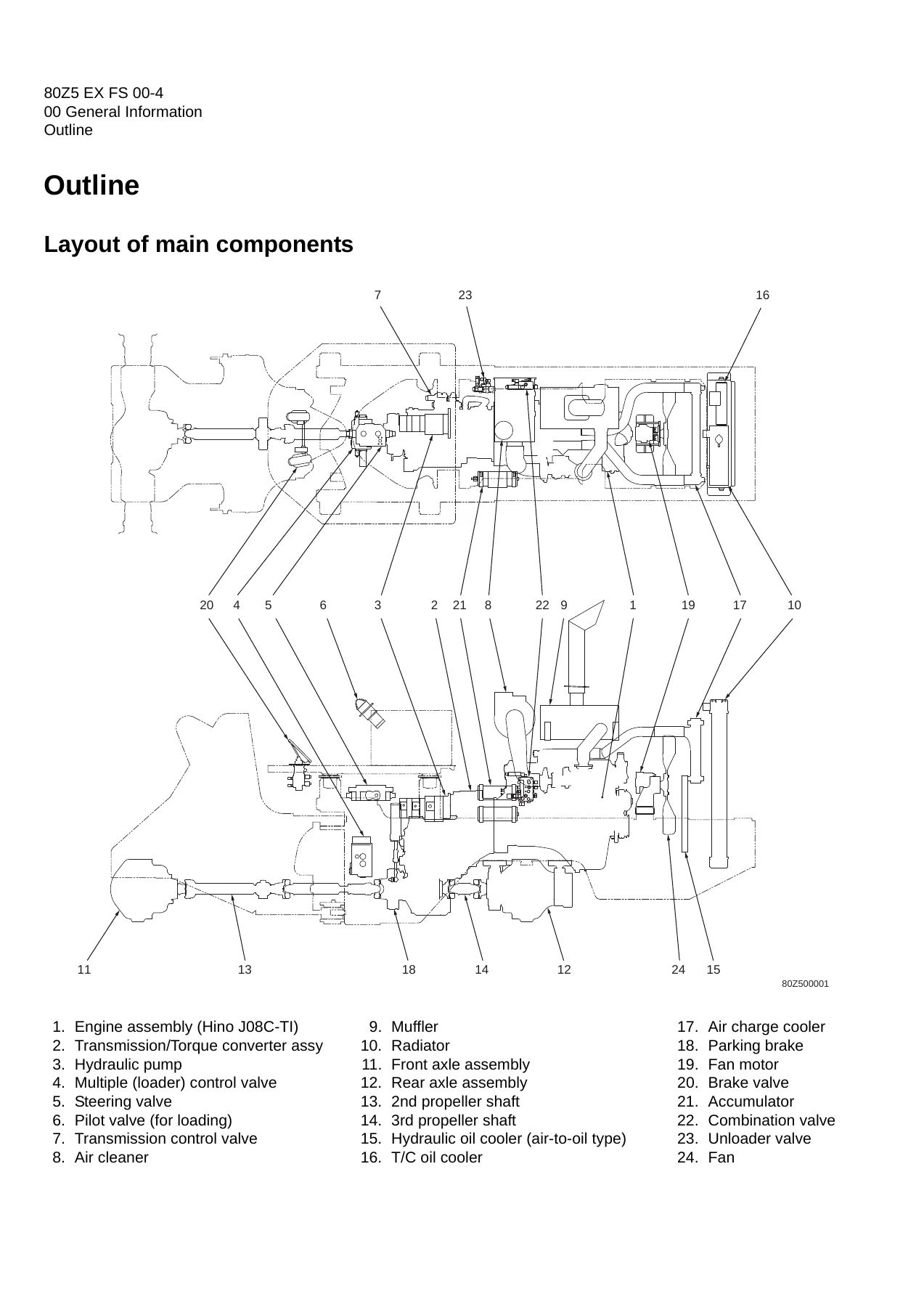
Layout of main componentsp. 18
Inspection and maintenance tablep. 19
Recommended lubricantsp. 22
Coolantp. 24
Coolant specificationp. 24
Recommended mixture of antifreezep. 24
Lubrication chartp. 25
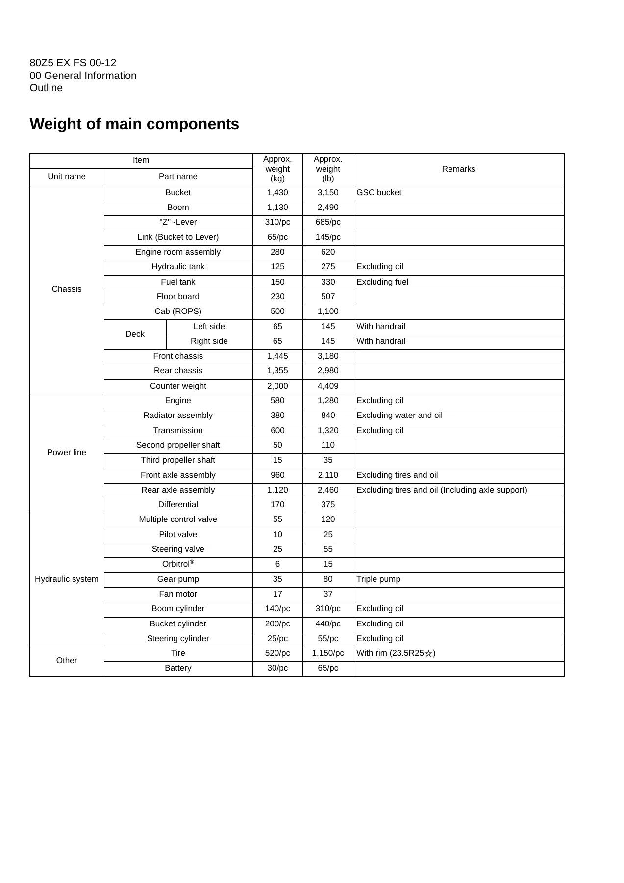
Weight of main componentsp. 26
Bolt tightening torquep. 27
Hexagon boltp. 27
Flanged hexagon boltp. 30
Hose band tightening torquep. 31
Liquid gasket and screw lock agentp. 32
Cautions regarding parts removalp. 32
Cautions regarding reassemblyp. 32
Screw lock agent application procedurep. 33
How to wind a seal tapep. 33
Cautions regarding welding repair servicep. 34
03 Measurement for Performance Checkp. 37
Cautions on Safetyp. 38
Standard Measurement Values for Performance Checkp. 39
12 Function & Structure Chassis Groupp. 41
Front Chassisp. 42
Loading linkagep. 42
Loading linkage pinp. 44
Rear Chassisp. 45
Fuel tankp. 45
Floor board mountp. 46
Floor boardp. 46
Viscous mountp. 46
Center Pinp. 47
Upper center pinp. 47
Lower center pinp. 47
Dust sealp. 48
13 Check & Adjustment Chassis Groupp. 49
Linkage Pinp. 50
Linerp. 50
Adjustmentp. 51
Center Pinp. 52
Adjusting shimp. 52
Installing bearing coverp. 52
Installing bearing outer ringp. 53
22 Function & Structure Power Groupp. 55
Power Linep. 56
Engine / Transmissionp. 57
Engine / transmission mountp. 57
Accelerator Pedalp. 58
Fuel Controlp. 59
Radiatorp. 60
Radiator mountp. 61
Propeller Shaftp. 62
Second propeller shaft assemblyp. 63
Front differential – Transmissionp. 63
Third propeller shaft assemblyp. 64
Transmission – Rear differentialp. 64
Axle Assemblyp. 65
Axle Supportp. 66
Torque Proportional Differential Gear (TPD)p. 68
Function of T.P.Dp. 70
Operation of T.P.Dp. 71
Limited Slip Differential (LSD) (option)p. 72
LSD Structurep. 72
LSD functionp. 75
LSD operationp. 75
23 Check & Adjustment Power Groupp. 77
Enginep. 78
Measuring engine speedp. 78
Measurement instrumentp. 78
Standard measurement valuep. 78
Measuring engine oil pressurep. 78
Measurement instrumentp. 78
Install positionp. 78
Standard measurement valuep. 78
Propeller Shaftp. 79
Propeller shaft phasep. 79
Second propeller shaft alignmentp. 79
Tightening torquep. 80
Axlep. 81
Axle nut tightening procedurep. 81
Differential gear adjustment procedurep. 82
Preload adjustmentp. 83
Bearing installationp. 83
Oil seal installationp. 83
Adjusting tooth contactp. 84
32 Function & Structure Torque Converter and Transmission Groupp. 87
Torque Converterp. 88
Torque converter structurep. 88
Power flow pathp. 88
Torque multiplicationp. 88
Torque Converter Gear Pumpp. 89
Gear pump specificationsp. 89
Transmissionp. 90
Clutch combinationp. 90
Shift lever positionp. 90
Downshift button operationp. 90
Gear train and number of teethp. 91
Clutch specificationsp. 92
Friction platep. 92
Clutch Packp. 93
Forward and 3rd speed clutchesp. 93
Reverse and 2nd speed clutchesp. 94
1st speed clutchp. 95
4th speed clutchp. 96
Power Flow Path in the Transmissionp. 97
Forward 1st speed power flow pathp. 97
Forward 2nd speed power flow pathp. 97
Forward 3rd speed power flow pathp. 98
Forward 4th speed power flow pathp. 98
Reverse 1st speed power flow pathp. 99
Reverse 2nd, 3rd, and 4th speeds power flow pathsp. 99
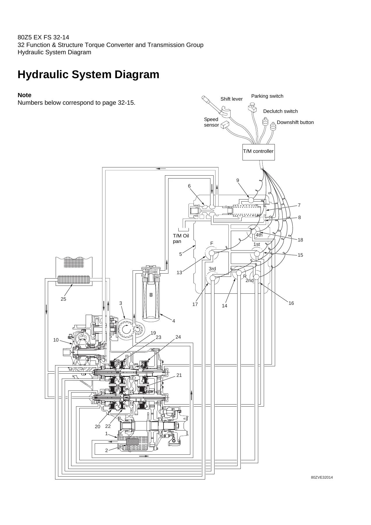
Hydraulic System Diagramp. 100
Hydraulic Circuit Diagramp. 101
Oil Flowp. 102
Oil flow in the torque converter linep. 102
From torque converter gear pump to torque converterp. 102
From torque converter to cooling circuitp. 102
From cooler to lubrication circuitp. 102
Oil flow to the clutchp. 102
To forward and reverse clutchesp. 102
To speed clutchp. 102
T/C and T/M Oil Circulationp. 103
Control Valvep. 104
System diagramp. 105
Modulation Mechanismp. 106
Clutch control oil pressure curvep. 107
Traveling at forward 1st speedp. 108
Pressure holdingp. 108
Changing from forward 1st speed to reverse 1st speedp. 109
Releasing forward clutch and feeding initial oil to reverse clutchp. 109
Trimmer engagementp. 110
Low-pressure holdingp. 110
Clutch engagement startingp. 111
Pressure increasep. 111
Clutch Solenoid Valvep. 112
For forward/reverse and speed clutchesp. 112
After power-off (clutch disengaged status)p. 112
After power-on (clutch engaged status)p. 113
For trimmerp. 114
After power-off (high clutch pressure status)p. 114
After power-on (just after switching clutch)p. 115
33 Check & Adjustment Torque Converter and Transmission Groupp. 117
Clutch Oil Pressurep. 118
Measuring clutch oil pressurep. 118
42 Function & Structure Hydraulic Groupp. 119
Flushing Hydraulic Circuitp. 120
Purpose of flushingp. 120
Cautions on Hydraulic Parts Replacementp. 121
Hydraulic Circuit Symbolsp. 122
Hydraulic linesp. 122
Pumps & motorsp. 122
Cylindersp. 122
Operation methodsp. 123
Pressure control valvep. 123
Flow control valvep. 123
Directional control valvep. 124
Check valvep. 124
Miscellaneous hydraulic symbolsp. 125
Hydraulic System Operationp. 126
Hydraulic system operation outlinep. 126
Loading systemp. 126
Steering systemp. 127
Fan motor systemp. 127
Ride control system (OPT)p. 127
Layout of Hydraulic Unitsp. 128
Hydraulic Tankp. 129
Hydraulic tank specificationsp. 129
Hydraulic oil level checkp. 129
Hydraulic tank (S/N 0501~0510)p. 130
Hydraulic tank breather valve (tank cap) (S/N 0501~0510)p. 131
Hydraulic tank (S/N 0511~)p. 132
Hydraulic tank breather valve (tank cap) (S/N 0511~)p. 133
Hydraulic Pumpp. 134
Hydraulic pump specificationsp. 134
Hydraulic pump principlep. 135
Hydraulic pump wear platep. 136
Hydraulic pump bushing lubricationp. 136
Hydraulic Cylinderp. 137
Boom cylinderp. 137
Bucket cylinderp. 137
Steering cylinderp. 138
Hydraulic cylinder specificationsp. 139
Loading Systemp. 140
Reducing Valve (for Pilot Pressure)p. 141
Pilot Valvep. 142
Pilot valve functionp. 144
Pilot valve operation (modulated position)p. 144
Pre-detent and detent magnet solenoidp. 146
Multiple Control Valve (KML28/2T102)p. 147
Multiple control valve specificationsp. 148
Multiple control valve main relief valvep. 149
Main relief valve operationp. 149
Adjusting set pressurep. 149
Multiple control valve overload relief valve (with make-up function)p. 150
Overload relief valve operationp. 150
Make-up valve operationp. 151
Adjusting set pressurep. 151
Multiple control valve make-up valvep. 152
Make-up valve operationp. 152
Multiple control valve bucket spoolp. 153
Bucket spool operationp. 153
Multiple control valve boom spoolp. 155
Boom spool operationp. 155
Adapter (Orifice)p. 158
Ride Control (OPT)p. 159
Ride control hydraulic circuitp. 159
Ride control functionp. 159
Ride control operationp. 160
Preparation mode (ride control switch is OFF)p. 160
Running mode (ride control switch is ON)p. 161
Ride control valve assemblyp. 162
Solenoid valvep. 165
Accumulator (for ride control)p. 167
Accumulator functionp. 167
Steering Systemp. 168
Orbitrol®p. 169
Orbitrol® structurep. 169
Valve partp. 169
Rotor partp. 170
Orbitrol® specificationp. 170
Orbitrol® operationp. 171
Neutralp. 171
Turnp. 172
Orbitrol® feed-back mechanism operationp. 173
Steering speed and flow rate controlp. 174
Hydraulic pump oil amount and steering forcep. 174
Orbit rotor operation principlep. 175
Steering Valve (KVS25-A3.0/20)p. 176
Steering valve operationp. 178
Steering plunger variable throttlep. 180
Steering valve flow control plungerp. 181
Steering valve main relief valvep. 182
Steering valve overload relief valvep. 184
Overload relief valve operationp. 185
Make-up valve operationp. 185
Steering pilot circuit and its operationp. 186
Flow amplifier notch and pilot orificep. 187
Stop Valvep. 188
Stop valve functionp. 189
Stop valve operationp. 189
Reducing Valve (for Orbitrol®)p. 190
Steering Line Filterp. 191
Fan Motor Systemp. 192
Mounting of fan motorp. 192
Fan Motor Linep. 193
Fan motorp. 194
Secondary Steering (OPT)p. 195
Secondary steering operationp. 196
Secondary steering motor and pumpp. 197
43 Check & Adjustment Hydraulic Groupp. 199
Loading/Steering Circuit Relief Valve/Ride Control Circuit Reducing Valve (OPT)p. 200
Loading circuit relief valve setting pressuresp. 200
Measuring loading circuit main relief pressurep. 202
Measuring loading circuit overload relief pressurep. 203
Measuring pilot circuit relief pressurep. 204
Ride control circuit reducing valve setting pressures (OPT)p. 205
Measuring ride control circuit reducing pressurep. 206
Steering circuit relief valve setting pressuresp. 207
Measuring steering circuit main relief pressurep. 209
Measuring steering circuit overload relief pressurep. 210
Measuring pilot circuit relief pressure (reducing pressure)p. 211
Hydraulic Cylinderp. 212
Cylinder natural driftp. 212
Stop Valvep. 214
Stop valve adjustment procedurep. 214
52 Function & Structure Brake Groupp. 215
Brake System Outlinep. 216
Service brakep. 216
Parking brakep. 216
Adjustment of axle internal pressurep. 216
Brake Units Layoutp. 217
Unloader Valvep. 218
Unloader valve operationp. 219
Valve Unitp. 220
Accumulatorp. 221
In-Line Filterp. 222
Brake Valvep. 223
Brake valve performance chartp. 224
Brake valve outlinep. 225
While the valve is not operatingp. 225
While the valve is operatingp. 226
While the valve is releasingp. 226
Service Brakep. 227
Service brake operationp. 227
Service brake friction platep. 228
Service brake steel platep. 228
Brake circuit air bleeding procedurep. 229
Bleeding air from brake pipes and axle housing hubsp. 229
Parking Brakep. 230
Parking brake operationp. 231
Parking brake solenoid valvep. 232
Solenoid valve operationp. 232
Solenoid valve specificationsp. 232
Parking Brake Manual Releasep. 233
Parking Brake Spring Chamberp. 235
Brake Circuit Check Valvep. 236
Pressure Switchp. 237
Pressure switch (for stop lamp)p. 237
Pressure switch (for declutch)p. 238
53 Check & Adjustment Brake Groupp. 239
Brake Circuit Oil Pressurep. 240
Unloader valve setting pressurep. 240
Unloader valve setting pressure measurementp. 241
Brake valve oil pressurep. 242
Brake valve oil pressure measurementp. 242
Brake valve performancep. 243
Service Brakep. 244
Service brake performance checkp. 244
Service brake friction plate wear measurementp. 245
Cautions on installing brake discsp. 246
Parking Brakep. 247
Parking brake performance checkp. 247
Parking brake clearance adjustmentp. 248
Adjustment procedurep. 249
Brake lining abrasion checkp. 249
62 Function & Structure Electrical Groupp. 251
How to Use Electrical Wiring Diagramp. 252
Electrical Cable Color Codesp. 253
Electrical Circuit Symbolsp. 254
Sensor Mountp. 255
Fusep. 256
Fuse boxp. 256
Fusible linkp. 257
Engine Start Circuitp. 258
Engine start circuit diagramp. 258
Neutral starterp. 259
Shift lever neutral (N) positionp. 259
Shift lever forward/reverse (F/R) positionp. 259
Starter switchp. 260
Battery relayp. 261
Battery relay operationp. 261
Neutral relayp. 262
Safety relayp. 263
Safety relay connection diagramp. 263
Safety relay specificationsp. 264
Safety relay operationp. 265
Starter motorp. 267
Starter motor specificationp. 268
Auxiliary cold starterp. 269
Auxiliary cold starter operationp. 270
Power Generating/Charging Circuitp. 271
Alternatorp. 271
Principle of alternator power generationp. 272
IC regulatorp. 273
IC regulator operationp. 273
Characteristics of Ziener diodesp. 275
Engine Stop Circuitp. 276
Stop solenoidp. 276
Emergency relayp. 277
Transmission Control Circuit and Monitor Circuitp. 278
Controller (S/N 0501~0700)p. 278
LED inspection windowsp. 279
Controller (Machine control unit (MCU)) (S/N 0701~)p. 281
Connectorp. 282
Controller (MCU) connection diagramp. 283
Controller functionp. 285
Forward/reverse (F/R) shifting and speed changep. 285
Automatic shiftp. 289
Machine speed sensorp. 290
Switching from automatic to manualp. 291
Downshift button operationp. 292
Transmission cut off (Declutch)p. 293
Pressure switch for inching (declutch)p. 294
Back-up alarmp. 295
Parking brakep. 296
Transmission controller (MCU) failure warningp. 298
Secondary steering functionp. 299
Monitoring systemp. 300
Items to be monitored and operation conditionp. 300
Operation monitor lampsp. 301
Instrument Panel and Switchp. 302
Instrument panelp. 302
Instrument panel rear surfacep. 304
Gauge circuitp. 306
Temperature sensorp. 307
Fuel level sensorp. 308
Electrical Detent Circuitp. 309
Bucket levelerp. 309
Proximity switchp. 309
Detent solenoidp. 310
Boom kick-outp. 311
Floatp. 311
Proximity switchp. 311
Detent solenoidp. 312
Diodep. 313
Diode check methodp. 314
Caution for diode check methodp. 314
Continuity check modep. 314
Diode check modep. 314
Resistance check modep. 315
Surge voltage and surge suppression diodesp. 316
Diagnostic System (S/N 0501~0700)p. 317
Diagnostic system flowp. 317
Diagnostic failure history memory datap. 318
Warning monitor/controlp. 318
Failure codep. 319
Malfunction mode symbolp. 320
Diagnostic (T/M controller) failure code detection conditionp. 321
Diagnostic failure history indication and deletionp. 322
Failure history indicationp. 322
Failure history deletionp. 322
Diagnostic switchp. 324
63 Check & Adjustment Electrical Groupp. 327
Cautions Regarding Electric Circuit Checkp. 328
Disconnecting or reinstalling connectorp. 328
How to attach the probes of the circuit testerp. 330
Electrical Transmission Control System Troubleshooting Flowchart (S/N 0501~0700)p. 331
Standard troubleshooting flowchartp. 331
Transmission Controller Abnormal Operation Judgmentp. 332
Transmission controller checkp. 332
When the "controller failure" monitor lamp lights:p. 332
When the output units (solenoid valve, etc.) do not operate properly:p. 332
If the input units or circuit are not defectivep. 333
Transmission controller LED indicatorp. 334
Electrical Circuit Checkp. 336
Shift lever input electrical circuit checkp. 336
Inching (Declutch) input electrical circuit checkp. 338
Downshift button input electrical circuit checkp. 340
Machine speed sensor input electrical circuit checkp. 341
Clutch solenoid valve output electrical circuit checkp. 342
Transmission trimmer plug solenoid valve electrical circuit checkp. 345
Neutral relay electrical circuit checkp. 348
Parking brake electrical circuit checkp. 350
Gauge circuit electrical circuit checkp. 352
Bucket positioner electrical circuit checkp. 354
MODM (S/N 0701~)p. 356
MODM functionp. 356
Monitor Changeoverp. 356
Changing display from one function to nextp. 356
MODM: Input/output monitor – Input/output signal correspondence tablep. 362
72 Function & Structure Operator Station Groupp. 365
Cabinp. 366
Glassp. 367
Wiper mountp. 370
Front wiperp. 370
Rear wiper (option)p. 370
Wiper motorp. 371
Operator Seatp. 373
Steering and Transmission Shift Leverp. 374
Tilt casep. 375
Column shaftp. 376
Shift leverp. 376
Air Conditionerp. 377
Denso air conditioner componentsp. 377
Air conditioner specifications (system performance)p. 377
Denso air conditioner structurep. 378
Cooling unitp. 378
Heater and accessoriesp. 380
Air distributor (hood & defroster selection box)p. 380
Air compressor (with magnetic clutch)p. 381
Condenser unitp. 381
Control unitp. 382
Function of cooling mechanismp. 383
Principle of coolingp. 383
Refrigerantp. 384
Refrigerant characteristicsp. 385
Cooling circuitp. 386
Electrical circuitp. 387
Control schematic drawingp. 387
Air conditioner functions of componentsp. 388
Control panelp. 388
Air conditioner unitp. 395
Compressor and magnetic clutchp. 404
Condenser unitp. 407
Receiver dryerp. 409
Sight glassp. 411
Pressure switchesp. 411
Pressure relief valvep. 413
Relay Ap. 414
Relay Bp. 414
Refrigerant hosep. 415
Charge of refrigerantp. 416
Work procedurep. 417
Refrigerant charging toolsp. 419
Refrigerant charging procedurep. 422
Troubleshooting using the gauge manifoldp. 428
Air conditioner troubleshootingp. 433
Fault diagnosis procedurep. 433
73 Check & Adjustment Operator Station Groupp. 441
Air Conditionerp. 442
Adjustment of lubricating oil quantity when components of air conditioner are replacedp. 442
When the compressor is replacedp. 443
When the evaporator is replacedp. 444
When the condenser is replacedp. 444
Adjustment of air gap (between hub and rotor) in compressor magnetic clutchp. 445
Compressor V-belt adjustmentp. 446
Belt adjustment procedurep. 447
Belt adjustment valuep. 447
Parts to be replaced periodicallyp. 448
Air filtersp. 448
Receiver dryerp. 448
INDEXp. 449
Maintenance Logp. 454
Notesp. 458

Read end to end, the volume builds a complete picture of the 80Z5 as a system rather than a collection of parts. The function-and-structure chapters explain the design intent behind each assembly – why the torque proportioning differential behaves differently from a conventional differential, how the modulation mechanism softens clutch engagement, what the stop valve does shortly before a full turn, how the ride control accumulator absorbs boom pitch. The matching check-and-adjustment chapters then convert that understanding into measurable numbers: relief pressures, clutch pressures, drift limits, preloads, air gaps, clearances and setting pressures, each with the gauge port, port size, oil temperature condition and the procedure used to obtain a valid reading.

What Makes This Volume Useful in the Workshop

Two things set this manual apart from a plain parts list. The first is the quantity of cutaway and schematic artwork. The torque converter and transmission section shows the power flow path for each forward and reverse speed, the hydraulic circuit and system diagrams, and the clutch control oil pressure curve that explains how the trimmer solenoid valve and trimmer plug shape the pressure rise. The hydraulic section documents the multiple control valve, the steering valve, the Orbitrol and the fan motor line with operating descriptions that trace oil from the pump through to the cylinder and back through the cooler and filter. The brake section does the same for the unloader valve, brake valve and accumulator circuit.

The second is that every explanation is tied to a check. The pilot line reducing valve is described, and then the check-and-adjustment chapter tells you the set pressure and where to connect the gauge. The centre pin is drawn with its bearings, shims and dust seals, and the adjustment chapter gives the shim clearance and bearing outer ring split orientation. This pairing means the manual can be used to decide whether a machine has a genuine fault or is simply at the edge of its normal range.

Serial number awareness runs throughout. The hydraulic tank is split between two build ranges, and separate wiring and connection diagrams are provided for the earlier and later serial groups in the drawings section. Fuel level sensor and magnet plug variations are noted as well. Buyers should check their machine serial against the ranges printed in the manual before ordering.

Torque, Capacity and Reference Data

General Information carries a full bolt tightening torque listing for metric and unified threads at 8.8 and 10.9 strength, a separate flanged hexagon bolt table, and hose band tightening torques with the correct band position relative to the pipe beading. Recommended lubricants, refill capacities, coolant mixture ratios for a range of ambient temperatures, a lubrication chart with grease and oil points marked across the machine, and approximate weights for the major components are all included, which makes the volume useful for planning a lift or a rebuild as well as for routine servicing.

Who This 80Z5 Shop Manual Is For

Owners and operators who want to understand what the gauges and warning lamps are actually telling them will find the monitoring and diagnostic sections useful. Fleet maintenance planners get the inspection and maintenance table with operating-hour intervals and the lubrication chart. Technicians and independent repair shops get the functional descriptions, the adjustment procedures, the relief and setting pressures, the electrical circuit checks with expected voltages and resistances, and the wiring and hydraulic diagrams needed to trace a fault to a component rather than guessing at it.

Get the Manual and Get to Work

IMAGES PREVIEW

80Z5 Wheel Loader Shop Manual - General Information, Functions and Structure 93209-00554 — PDF page 18 preview
80Z5 Wheel Loader Shop Manual - General Information, Functions and Structure 93209-00554 — PDF page 26 preview
80Z5 Wheel Loader Shop Manual - General Information, Functions and Structure 93209-00554 — PDF page 100 preview

With this 80Z5 wheel loader shop manual on hand you can diagnose hydraulic and steering complaints against real setting pressures, verify loader and bucket cylinder drift against the published limits, measure clutch oil pressure and interpret the modulation curve, check and adjust service and parking brake performance, work through the transmission control electrical circuits terminal by terminal, and rebuild the centre pin, axle or differential with the correct preloads, shims and tooth contact pattern. Correct procedures and correct specifications are what separate a repair that lasts from a comeback, and this volume supplies both for the systems it covers. Delivery is instant: a PDF download with no shipping and no waiting, ready to open on a laptop, tablet or phone in the workshop and to print the pages you need for the job.
Reviews

There are no reviews yet.

Be the first to review “80Z5 Wheel Loader Shop Manual – General Information, Functions and Structure 93209-00554”

What Our Customers Say

★★★★★ Live reviews from customers
Loading customer reviews...
0
    0
    Your Cart
    Your cart is emptyReturn to Shop
    🛒
    Recently Purchased
    🕒 verified order