★ TRUSTED BY 321,897+ PROFESSIONALS WORLDWIDE
🏒
Trusted Business
Verified & Licensed
πŸ›‘οΈ
Virus Free Files
100% Safe Downloads
πŸ”’
Secure Payment
SSL Protected
⚑
Instant Delivery
Available Immediately
Sale!

Daewoo Solar 210W-V Wheel Excavator Shop Manual 023-00064E – 2002 PDF Repair Guide

Original price was: $39.95.Current price is: $24.95.

Complete 824-page Daewoo Solar 210W-V wheel excavator shop manual (document 023-00064E) covering the DB58TIS engine, ZF 2HL-100 transmission, axles, hydraulic pumps, control valves, electrical system and full schematics.

⚑
Instant PDF Download
Available immediately
πŸ’Ύ
Save to Your Device
Download & keep forever
πŸ›‘οΈ
Antivirus Scanned
100% virus-free
🌍
Trusted Worldwide
175,000+ customers

Description

The Daewoo Solar 210W-V Shop Manual is the complete workshop repair guide for the Solar 210W-V wheel excavator, covering serial number 1001 and up. Issued by Daewoo Heavy Industries under document number 023-00064E, this 824-page PDF takes a technician through every major system on the machine – from the Daewoo DB58TIS turbocharged diesel engine and ZF 2HL-100 transmission to the Toshiba DX28 main control valve, swing motor, travel motor, front and rear axles, and the full hydraulic and electrical schematics.

File Details

  • Manual type: Shop Manual (workshop service and repair)
  • Brand: Daewoo Heavy Industries Ltd.
  • Model: Solar 210W-V wheel excavator
  • Document number: 023-00064E
  • Serial number coverage: 1001 and Up
  • Language: English
  • File format: PDF
  • Page count: 824 pages
  • Publication date: 2002 (individual sections carry 1999, 2000, 2001 and 2002 revision dates)

Chapters Covered in the Daewoo Solar 210W-V Shop Manual

The manual is divided into the standard Daewoo shop manual groups, each carrying its own section number so a technician can jump straight to the system in front of them:

  • Safety – Wheel Excavator Safety (S0102025K): safety alert symbols, general hazard information, before starting engine, machine operation, maintenance, battery, towing, shipping and lifting with sling.
  • Specifications – Specifications for Solar 210W-V (S0202045K): component location, general dimensions, working range, hydraulic cylinders, engine specifications and performance curves, approximate weight of workload materials, general specifications, hydraulic system component specifications and performance tests.
  • General Maintenance – General Maintenance Procedures (S0302000) and Standard Torques (S0309000): welding precautions, hydraulic system cleanliness and oil leaks, bearing inspection, torque values for standard metric and U.S. fasteners, hose clamps, split flanges and torque wrench extension tools.
  • Upper Structure – Cab (S0402040K), Counterweight (S0403015K), Fuel Tank (S0405075K), Fuel Transfer Pump (S0405500), Swing Bearing (S0407010) and Swing Reduction Gearbox (S0408040).
  • Lower Structure and Chassis – Ram Lock Valve Operation (S0503000).
  • Engine and Drive Train – Front Axle (S0602100), Transmission ZF 2HL-100 (S0602110), Air-Conditioner (S0605060K) and Drive Coupling / Main Pump (S0609000).
  • Hydraulics – Hydraulic System Troubleshooting, Testing and Adjustment (S0702115K), Accumulator (S0703010K), Center Joint / Swivel (S0704070), Cylinders (S0705000), Swing Motor (S0707250), Travel Motor (S0707350), Main Pump with Regulator, Steering Pump and Brake Pump (S0708430), Brake Supply Valve (S0709220), Counterbalance Valve (S0709300), Main Control Valve Toshiba DX28 (S0709440), Pilot Control Valve / Work Lever / Joystick (S0709451K), Steering Valve (S0709710), Dozer Control Valve (S0709905K) and Hydraulic Schematic (S0792101K).
  • Electrical System – Electrical System (S0802125K) and Electrical Schematic (S0892101K): electric supply, engine starting and preheat, engine stop, charging, monitoring system, instrument panel, control unit, e-EPOS electronic hydraulic control, power mode control, work mode control, engine control system, auto idle, power boost, cruise control, self-diagnostic function, wiper system and overload warning device.
  • Attachments – Boom and Arm (S0902080) and Bucket (S0904000).

Complete PDF Bookmark Tree

Complete Bookmarks

The complete bookmarks in the β€œDaewoo Solar 210W-V Wheel Excavator Shop Manual 023-00064E – 2002 PDF Repair Guide” are as follows:

Safetyp. 7
Wheel Excavator Safety S0102025Kp. 9
To the Operator of a Daewoo Excavatorp. 11
Learn the Signal Words Used with the Safety Alert Symbolp. 13
General Safety Essentialsp. 14
Accessory Applicationsp. 14
Lifting Capacity Rating Configurationp. 14
Location of Safety Labelsp. 14
Summary of Safety Precautions for Lifting in Digging Modep. 15
Unauthorized Modificationsp. 16
General Hazard Informationp. 16
Safety Rulesp. 16
Safety Featuresp. 16
Inside Operator's Compartmentp. 17
Clothing and Personal Protective Itemsp. 18
Breathing Masks, Ear Protection May be Requiredp. 18
Mounting and Dismountingp. 19
Fuel, Oil and Hydraulic Fluid Fire Hazardsp. 20
Precautions When Handling Fluids at High Temperaturep. 20
Asbestos Dust Hazard Preventionp. 21
Injury from Work Equipmentp. 21
Fire Extinguisher and First Aid Kitp. 22
Protection from Falling or Flying Objectsp. 22
Attachment Precautionsp. 23
Accumulatorp. 23
Indoor Ventilationp. 24
Emergency Exitp. 24
Before Starting Enginep. 25
Work Site Precautionsp. 25
Checks Before Starting Enginep. 26
Engine Startingp. 27
Before Operating Machinep. 27
Machine Operationp. 28
When Swinging or Changing Direction of Travelp. 28
Travel Precautionsp. 28
Traveling on Slopesp. 29
Prohibited Operationsp. 30
Precautions for Operationp. 30
Avoid High-voltage Cablesp. 31
Operate Carefully on Snow, Ice and in Very Cold Temperaturesp. 31
Operations on Slopesp. 32
Parking Machinep. 32
Never Let Anyone Ride on Attachmentp. 32
Maintenancep. 33
Warning Tagp. 33
Clean Before Inspection or Maintenancep. 33
Proper Toolsp. 34
Use of Lightingp. 34
Fire Prevention and Explosion Preventionp. 34
Burn Preventionp. 35
Welding Repairsp. 36
Warning for Counterweight and Front Attachment Removalp. 36
Precautions for Removal, Installation, and Storage of Attachmentsp. 37
Precautions when Working on Machinep. 37
Lock Inspection Coversp. 37
Crushing Prevention and Cutting Preventionp. 37
Supports and Blocking for Work Equipmentp. 38
Action When Abnormally Is Found During Inspectionp. 39
Precautions with High Pressure Line, Tubes and Hosesp. 39
Waste Materialsp. 40
Batteryp. 41
Battery Hazard Preventionp. 41
Boost Starting or Charging Engine Batteriesp. 42
Towingp. 43
Precautions When Towingp. 43
Shipping and Transportationp. 44
Obey State and Local Over-the-Road Regulationsp. 44
Lifting With Slingp. 44
Specificationsp. 45
Specifications for Solar 210W-V S0202045Kp. 47
General Descriptionp. 49
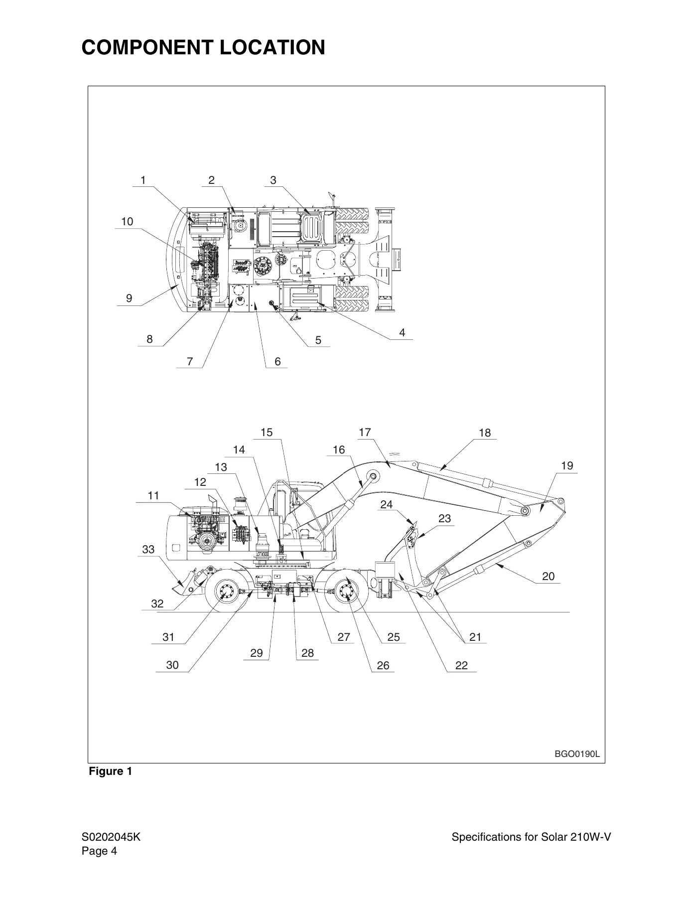
Component Locationp. 50
General Dimensionsp. 52
Dimensionsp. 52
Working Rangep. 54
Hydraulic Cylindersp. 58
Engine Specificationsp. 60
Engine Performance Curves (DIN 6270 Standard)p. 62
Approximate Weight of Workload Materialsp. 64
General Specificationsp. 68
Hydraulic System Component Specificationsp. 70
System Component Specificationsp. 72
Drive Systemp. 72
Swing Mechanismp. 72
Brake Systemp. 73
Steering Systemp. 73
Chocking Systemp. 74
Performance Tests and Standardsp. 75
Standardsp. 75
Testsp. 76
Test Conditionsp. 76
Travel Speed Testsp. 77
Swing Speed Testp. 78
Swing Force Testp. 78
Cylinder Performance Testsp. 79
Boom Cylinders Testp. 79
Arm Cylinder Testp. 79
Bucket Cylinder Testp. 79
Hydraulic Cylinder Natural Drop Testp. 79
General Maintenancep. 81
General Maintenance Procedures S0302000p. 83
Welding Precautions and Guidelinesp. 85
Hydraulic System – General Precautionsp. 86
Maintenance Service and Repair Procedurep. 87
General Precautionsp. 87
Hydraulic System Cleanliness and Oil Leaksp. 88
Maintenance Precautions for Hydraulic System Servicep. 88
Oil Leakage Precautionsp. 88
Cleaning and Inspectionp. 89
General Guidelinesp. 89
Bearing inspectionp. 90
Standard Torques S0309000p. 97
Torque Values for Standard Metric Fastenersp. 99
Torque Values for Standard U.S. Fastenersp. 100
Type 8 Phosphate Coated Hardwarep. 102
Torque Values for Hose Clampsp. 103
Torque Values for Split Flangesp. 104
Torque Wrench Extension Toolsp. 105
Torque Multiplicationp. 105
Other Uses for Torque Wrench Extension Toolsp. 106
Tightening Torque Specifications (Metric)p. 106
Upper Structurep. 109
Cab S0402040Kp. 111
Removalp. 113
Installationp. 116
Counterweight S0403015Kp. 119
Generalp. 121
Removalp. 123
Installationp. 125
Fuel Tank S0405075Kp. 127
General Descriptionp. 129
Parts Listp. 130
Specificationsp. 131
Removalp. 132
Installationp. 136
Start-up Proceduresp. 138
Fuel Transfer Pump S0405500p. 139
General Descriptionp. 141
Theory of Operationp. 141
Troubleshootingp. 142
Replacement of Rotor and Vanep. 142
Replacement of Rear Coverp. 143
Replacement of Armaturep. 144
Swing Bearing S0407010p. 145
Swing Bearing Maintenancep. 147
Operating Recommendationp. 147
Measuring Swing Bearing Axial Playp. 147
Measuring Bearing Lateral Playp. 147
Swing Bearing Basic Operationp. 148
Rebuilding Swing Bearingp. 148
Swing Reduction Gearbox S0408040p. 151
General Descriptionp. 153
Theory of Operationp. 153
Parts Listp. 154
Specificationsp. 155
Special Tools and Materialsp. 156
Special Toolsp. 156
Troubleshooting, Testing and Adjustmentp. 157
Removalp. 158
Disassemblyp. 160
Cleaning and Inspection (Wear Limits and Tolerances)p. 165
Reassemblyp. 166
Installationp. 175
Lower Structure and Chassisp. 177
Ram Lock Valve Operation S0503000p. 179
Theory of Operationp. 181
Engine and Drive Trainp. 183
Front Axle S0602100p. 185
Special Toolsp. 187
Hub Nut Toolp. 187
Disassemblyp. 188
Planetary Endp. 188
Differential Gearp. 195
Cleaning and Inspection (Wear Limits and Tolerances)p. 200
Reassemblyp. 201
Differential Gearp. 201
Planetary Endp. 212
Start-up Proceduresp. 227
Axle Lubricationp. 227
Transmission (ZF2HL-100) S0602110p. 229
Transmission Operationp. 232
Special Toolsp. 233
Hub Nut Toolp. 233
Transmission Disassemblyp. 234
Detaching Drive (Input) Housingp. 234
Disassembly of Input Shaft and Brake Assemblyp. 235
Disassembly of Clutchp. 237
Disassembly of Planetary Carrierp. 242
Disassembly of Shift Lever and Helical Gearp. 243
Disassembly of Shift Lock (Version A)p. 248
Disassembly of Shift Lock (Version B)p. 250
Final Drive Disassemblyp. 252
Rear Axle Disassemblyp. 256
Differential Gear Disassemblyp. 263
Cleaning and Inspection (Wear Limits and Tolerances)p. 268
Differential Gear Reassemblyp. 269
Rear Axle Reassemblyp. 281
Final Drive Reassemblyp. 296
Transmission Reassemblyp. 301
Reassembly of Helical Gearp. 301
Reassembly of Shift Leverp. 303
Reassembly of Planetary Carrierp. 304
Adjusting Shift Leverp. 306
Pre assembling and Installing Clutchp. 307
Checking Clutchp. 314
Reassembly of Brake and Input Shaft Assemblyp. 315
Installing Drive (Input) Housingp. 319
Assembly of Shift Lock (Version A)p. 322
Assembly of Shift Lock (Version B)p. 326
Installing Oil Pumpp. 328
Installing Screw Plugs and Oil Linesp. 331
Start-up Proceduresp. 332
Axle Lubricationp. 332
Lubricationp. 332
Air-Conditioner S0605060Kp. 333
General Descriptionp. 335
Refrigerant Circulationp. 337
Control Panelp. 339
Control Specificationsp. 340
Temperature Level Control and Displayp. 341
Air Discharge According to Path Selectionp. 342
Air-conditioning System Circuit Diagramp. 344
Troubleshootingp. 346
Weight of R134a Gas Used In Machinesp. 349
Refrigerant System Repairsp. 351
Refrigerant Safe Handling Proceduresp. 351
Repair and Replacement Procedurep. 352
Refrigerant Recoveryp. 354
Vacuuming Refrigerant Systemp. 354
Leakage Checkp. 355
Refrigerant Chargingp. 356
Inspecting System For Leakagep. 358
Drive Coupling (Main Pump) S0609000p. 359
Drive Couplingp. 361
Special Toolsp. 362
Kawasaki / Tong Myung Pump Toolp. 362
Uchida Pump Toolp. 365
Drive Coupling Installationp. 366
Installation Procedurep. 371
Hydraulicsp. 373
Hydraulic System Troubleshooting, Testing and Adjustment S0702115Kp. 375
Hydraulic System – General Notesp. 378
Operation of Working Componentsp. 379
Boom Operating Circuitp. 379
Boom Up Circuitp. 379
Boom Down Circuitp. 379
Arm Operating Circuitp. 380
Arm Crowd Circuitp. 380
Arm Dump Circuitp. 381
Bucket Operating Circuitp. 381
Bucket Crowd Circuitp. 381
Bucket Dump Circuitp. 382
Swing Operating Circuitp. 383
Right Swing Operating Circuitp. 383
Left Swing Operating Circuitp. 383
Swing Relief Valve and Make-up Valvep. 383
Procedural Troubleshooting Baseline Recommendationsp. 384
Initial Checks and Tests to Establish Operating Condition of the Excavatorp. 384
Pilot Pressurep. 385
Adjustment and Testingp. 385
Power Mode Valvep. 386
Current Signal and Hydraulic Pressure Adjustmentsp. 386
Boom/Swing Priority Valvep. 387
Control Valve Pressure and Current Adjustmentsp. 387
Pressure Up Valvep. 388
Checks and Adjustmentsp. 388
Pump Input Power Controlp. 389
Pump Regulator Adjustmentp. 389
Flow Meter and Flow Meter Kit Installation and Testingp. 392
Swing System Troubleshootingp. 393
Precautions/Initial Checksp. 393
Swing Relief Valve Checking and Adjustmentp. 393
Troubleshooting – Swing Gearboxp. 395
Troubleshooting – Hydraulic Problemsp. 396
Troubleshooting – Control Valvep. 398
Troubleshooting – Joystick Control Valvep. 399
Accumulator S0703010Kp. 401
General Descriptionp. 403
Specificationsp. 404
Center Joint (Swivel) S0704070p. 407
General Descriptionp. 409
Parts Listp. 410
Troubleshooting, Testing and Adjustmentp. 412
Inspectionp. 412
Testingp. 412
Disassemblyp. 413
Reassemblyp. 414
Cylinders S0705000p. 415
General Descriptionp. 417
Theory of Operationp. 417
Parts Listp. 418
Special Tools and Materialsp. 420
Piston Nutp. 420
Piston Jigp. 424
Steel bush Jigp. 428
Dust Wiper Jigp. 432
Slipper Seal Jigp. 438
Slipper Seal Straightening Jigp. 442
Disassemblyp. 445
Assemblyp. 451
Swing Motor S0707250p. 455
General Descriptionp. 457
Theory of Operationp. 457
Swing Motor Anti-cavitation Make-up Valvep. 458
Relief Valvep. 459
Swing Brake Operationp. 459
Parts Listp. 462
Specificationsp. 464
Special Toolsp. 465
Disassemblyp. 466
Cleaning and Inspection (Wear Limits and Tolerances)p. 473
Reassemblyp. 475
Travel Motor S0707350p. 483
General Descriptionp. 486
Theory of Operationp. 486
Parts Listp. 488
Specificationsp. 489
Travel Motor General Disassembly and Reassembly Instructionsp. 490
Recommended Toolsp. 490
Precautions for Disassembly and Assemblyp. 490
Disassembly of Travel Motorp. 491
Appearance of Motorp. 491
Removal of counterbalance Valvep. 491
Removal of Outer Pipingp. 492
Removal of Stroke Limiterp. 493
Removal of Oil Sealp. 494
Removal of Control Unitp. 494
Removal of Control Valvep. 496
Disassemble Control Valvep. 498
Disassemble Stroke Limiterp. 499
Reassemble Stroke Limiterp. 500
Reassemble Control Valvep. 500
Installation of Control Valvep. 501
Reassembly of Travel Motorp. 504
Assembly of Control Unitp. 504
Installation of Oil Sealp. 506
Installation of Stroke Limiterp. 507
Installation of Outer Pipingp. 507
Installation of Counterbalance Valvep. 508
Main Pump (With Regulator, Steering Pump and Brake Pump) S0708430p. 509
General Descriptionp. 512
Gear (Pilot) Pumpp. 514
Relief Valvep. 514
Pump Regulator Descriptionp. 515
Horsepower Controlp. 515
Power Shift Controlp. 515
Negative Oil Discharge (Pump Bypass) Controlp. 515
Pump Regulator Operationp. 516
Pump Output Decreasep. 518
Pump Discharge Decreasep. 518
Pump Discharge Increasep. 518
Horsepower Controlp. 518
Overload Protectionp. 519
Regulator Adjustmentp. 519
Pump Input Power Control Adjustmentp. 520
Parts Listp. 522
Specificationsp. 527
Hydraulic Pump Performance Characteristicsp. 528
Troubleshooting, Testing and Adjustmentp. 529
Main Pumpp. 529
Disassemblyp. 530
General Disassemblyp. 530
Main Pump Disassemblyp. 531
Pump Regulator Disassemblyp. 533
Cleaning and Inspection (Wear Limits and Tolerances)p. 537
Reassemblyp. 539
Pump Regulator Reassemblyp. 539
Main Pump Reassemblyp. 543
Brake Supply Valve S0709220p. 547
Parts Listp. 550
Specificationsp. 551
Counterbalance Valve S0709300p. 553
General Descriptionp. 555
While Operating to Run Forwardp. 555
While Operating to Stopp. 555
While Operating to Backp. 555
Adjustment of Relief Valvep. 556
Troubleshootingp. 557
Counterbalance Valvep. 558
Recommended Toolsp. 558
Disassemblyp. 558
Order of Disassembly and Torque Valuesp. 559
Reassemblyp. 560
Main Control Valve (Toshiba DX28) S0709440p. 565
Control Valve Operationp. 569
Arm Priority Circuitp. 570
Bucket (Junction) Circuitp. 572
Main Relief Valvep. 574
Overload Relief Valvep. 575
Arm Load Holding Valvep. 577
Boom Load Holding Valvep. 580
Arm Regenerationp. 582
Boom Regenerationp. 584
Foot Relief Valvep. 585
Parts Listp. 586
Specificationsp. 595
Control Valve Drawing and Hydraulic Circuitp. 596
Disassembly and Reassemblyp. 601
General Disassemblyp. 601
General Reassemblyp. 601
Plunger Replacementp. 602
Main Plunger Element – Disassembly and Assemblyp. 603
Toolp. 603
Main Relief Valvep. 606
Overload Relief Valvep. 609
Arm Load Holding Valvep. 611
Boom Load Holding Valvep. 614
Arm Regeneration Valvep. 616
Bucket Unity Checkp. 617
Foot Relief Valvep. 618
Center Bypass Valve (CB Valve)p. 619
Boom Parallel Switch Valvep. 620
Boom Unity Check Valvep. 622
Check Valve – Locationsp. 623
Check Valvep. 624
Pilot Control Valve (Work Lever / Joystick) S0709451Kp. 627
General Descriptionp. 629
Theory of Operationp. 629
Parts Listp. 630
Specificationsp. 631
Removalp. 632
Disassemblyp. 635
Cleaning and Inspection (Wear Limits and Tolerances)p. 639
Reassemblyp. 640
Installationp. 645
Start-up Proceduresp. 646
Steering Valve S0709710p. 647
General Descriptionp. 649
Theory of Operationp. 650
Parts Listp. 652
Specificationsp. 653
Special Tools and Materialsp. 654
Special Toolsp. 654
Disassemblyp. 656
Reassemblyp. 665
Dozer Control Valve S0709905Kp. 679
Parts Listp. 681
Specificationsp. 682
Hydraulic Schematic (Solar 210W-V) S0792101Kp. 683
General Descriptionp. 685
Solar 210W-Vp. 686
General Notesp. 690
Electrical Systemp. 691
Electrical System S0802125Kp. 693
Troubleshooting – Electrical Systemp. 697
Overviewp. 698
Electric Supply Systemp. 699
Engine Starting Circuitp. 700
Operation During Start Processp. 700
Operation After Start Processp. 701
Engine Preheating Systemp. 702
Engine Stop Systemp. 703
Charging Systemp. 706
Monitoring Systemp. 708
Instrument Panelp. 710
Monitoring System Schematicp. 712
Operationp. 714
Instrumentsp. 714
Warning and Indicator Lightsp. 716
Control Unitp. 718
Operation Schematicp. 718
Operation Specificationp. 719
Console Warning Lightp. 720
Initial Operationp. 722
Mode Select Switchp. 723
Graphic Information Area Displayp. 724
Overviewp. 724
Main Menus for the Graphic Display Areap. 725
Menu Selection Buttonsp. 725
Main Menup. 726
Language settingp. 726
Time Settingp. 726
Filter/Oil informationp. 727
Special Menup. 728
Entering/Accessing and Exiting/Escaping Menusp. 728
Special Menu Selectionsp. 729
Electronic Hydraulic Control System (e-EPOS)p. 742
Power Mode Controlp. 744
Operationp. 745
Throttle Position Sensorp. 748
Power Mode Control – Circuit Diagramp. 750
Work Mode Controlp. 752
Operationp. 753
Work Mode Control – Circuit Diagramp. 754
Engine Control Systemp. 756
Engine Control Motorp. 757
Engine Control Dialp. 758
Engine Control Circuit Diagramp. 760
Automatic Deceleration Control (Auto Idle Control)p. 761
Automatic Deceleration Control Circuitp. 762
Operationp. 763
Engine Overheat Protection Systemp. 764
Power Boost Modep. 765
Operationp. 765
Power Boost Control – Circuit Diagramp. 766
Cruise Controlp. 768
Cruise Control Circuitp. 770
Adjusting Method of Engine Control Unitp. 772
Adjusting Method of Engine Control Systemp. 772
Adjusting Method of Engine RPMp. 774
Adjustment of TPS (Throttle Position Sensor)p. 779
Self-diagnostic Functionp. 784
e-EPOS Controllerp. 784
Engine Throttle Controllerp. 788
Wiper Systemp. 790
Wiper Circuitp. 790
Wiper Operationp. 790
Window Washer Operationp. 791
Overload Warning Devicep. 792
Overload Warning Device Circuit Diagramp. 792
Electrical Schematic (Solar 210W-V) S0892101Kp. 793
General Descriptionp. 795
Solar 210W-Vp. 796
Attachmentsp. 799
Boom and Arm S0902080p. 801
Front Attachment Pin Specificationsp. 803
Front Attachment – Removal and Installationp. 804
Arm Removal Procedurep. 804
Boom Removal Procedurep. 806
Installationp. 807
Arm Installation Procedurep. 807
Boom Installation Procedurep. 807
Start-up Proceduresp. 808
Bucket S0904000p. 809
Bucket Tooth Inspection and Replacementp. 811
Type 1p. 811
Type 2p. 812
Type 3p. 813
Bucket O-ring Replacementp. 815
Type 1p. 815
Type 2p. 816
Bucket Shimming Proceduresp. 818
New Bucket Installationp. 818
Type 1p. 818
Type 2p. 819
Bucket Attachment, Removal and Reversalp. 820
Detaching the Bucketp. 820
Attaching The bucketp. 820
Reversing the Bucketp. 821
Publication Request for Proposed Revisionp. 823

What this gives a technician is not a general overview but a working document. Every section follows the same pattern Daewoo used in its dealer workshops: theory of operation first, then removal, disassembly, cleaning and inspection with wear limits and tolerances, reassembly, installation and start-up procedures. Torque values, relief pressures, adjustment screws and wear limits appear in the same pages as the procedure that needs them, so the reader is not flipping between a repair chapter and a separate specification book.

Engine, Transmission and Axle Work

The engine and drive train group covers the Daewoo DB58TIS four-cycle in-line six-cylinder turbocharged water-cooled diesel in full specification detail – 102 mm x 118 mm bore and stroke, 5,785 cc displacement, 19.5:1 compression ratio and 157 ps at 2,200 rpm – together with its performance curves and fuel system data. The transmission chapter deals with the ZF 2HL-100 two-speed power shift planetary unit, including the input shaft and brake assembly, clutch, planetary carrier, helical gear, shift lever, shift lock versions A and B, final drive, rear axle and differential gear. The front axle chapter covers the planetary ends and the differential gear with measured shim thickness calculations, backlash adjustment, contact pattern checking and the multi-disc brake piston clearance table, so axle rebuilds can be completed to specification rather than by feel.

Hydraulics and Electrical Coverage

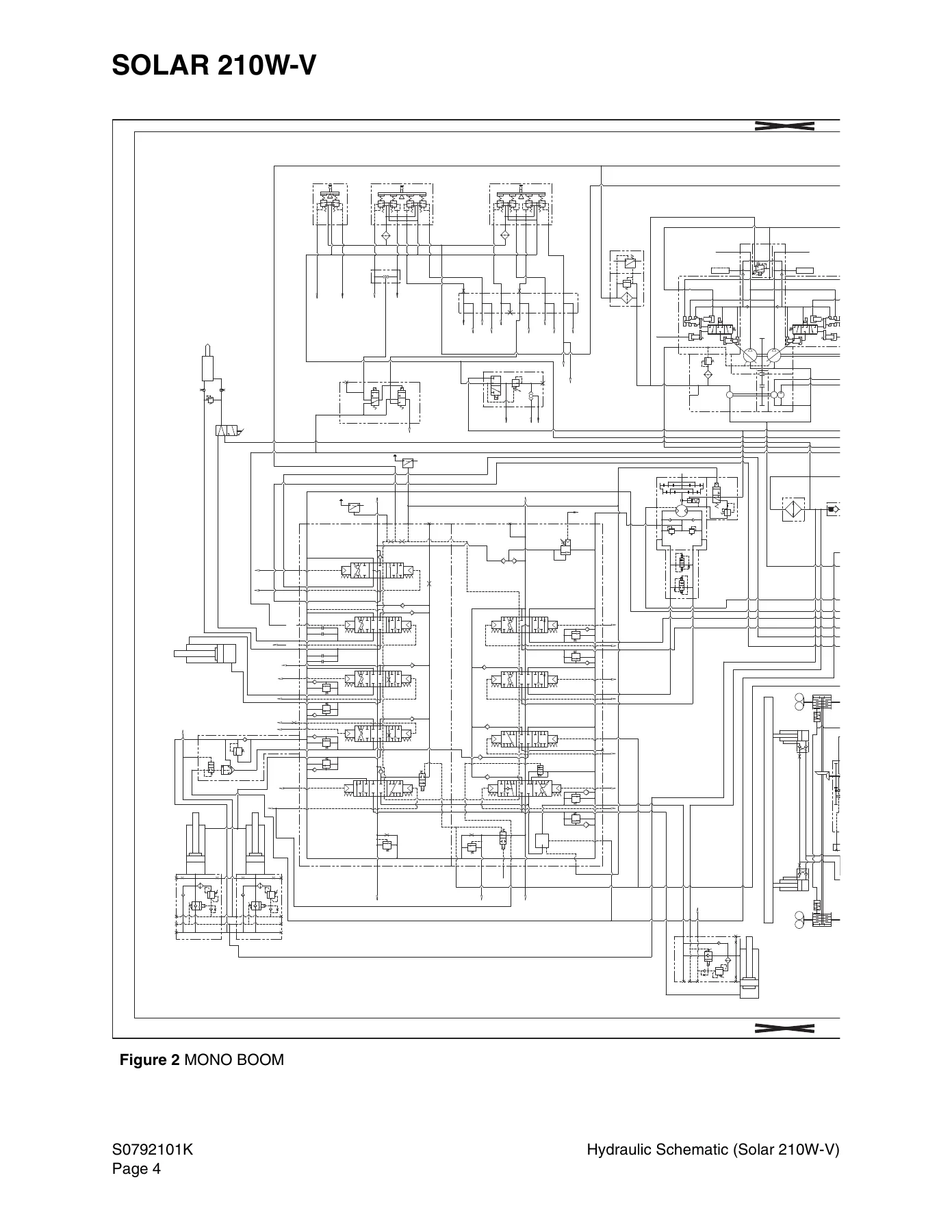
The hydraulic group is the deepest part of this Solar 210W-V shop manual. It includes the full troubleshooting, testing and adjustment procedure with a specified test sequence – pilot pressure, negative control pressure, main relief pressure, swing pressure, port relief pressure, power boost and standard performance tests – followed by individual chapters for the accumulator, center joint, cylinders, swing motor, travel motor, tandem main pump with regulators, brake supply valve, counterbalance valve, Toshiba DX28 main control valve, pilot control valve, steering valve and dozer control valve. Because it is a wheeled machine, the manual also carries the complete hydraulic schematic for the Solar 210W-V, including mono boom and articulated boom configurations.

On the electrical side the document covers the 24 V system end to end: batteries, battery relay, starter switch, fusible link, circuit breaker and fuse box, starting and preheat circuits, the engine stop motor circuit, charging system, monitoring system and instrument panel. The e-EPOS electronic hydraulic control system is documented with its power mode control, work mode control, engine throttle controller, throttle position sensor adjustment tables and the self-diagnostic failure code list. The electrical schematic for the Solar 210W-V is included as its own section.

Who This Daewoo Solar 210W-V Shop Manual Is For

This is the reference for anyone maintaining, repairing or rebuilding a Solar 210W-V wheel excavator – independent heavy equipment mechanics, fleet workshops, technical colleges and owners who do their own servicing. The procedures assume the reader has the machine in front of them and access to the special tools named in the text, and the safety group at the front sets out the lifting, blocking, pressure-release and lockout precautions that apply before any of it begins. Sections reference companion service literature for the operation and maintenance side, but everything needed for the mechanical, hydraulic and electrical repair work is contained in these pages.

Get the Complete Daewoo Solar 210W-V Shop Manual

With this manual on hand, the jobs it supports are broad: rebuilding the ZF 2HL-100 transmission, re-shimming and setting backlash in the front or rear axle differential, diagnosing a swing or travel motor that will not rotate, adjusting main relief and power boost pressure, tracing a faulty circuit through the instrument panel or e-EPOS controller, repacking a boom, arm or bucket cylinder, and setting bucket pin end play correctly. Correct procedures and the right torque and pressure values are what separate a repair that lasts from one that returns – and on a machine this size the difference is expensive.

IMAGES PREVIEW

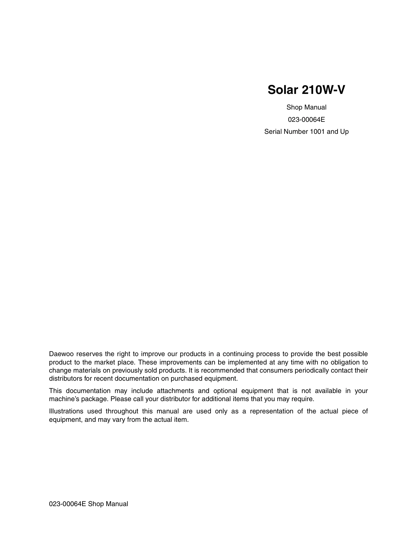
Daewoo Solar 210W-V Wheel Excavator Shop Manual 023-00064E - 2002 PDF Repair Guide β€” PDF page 1 preview
Daewoo Solar 210W-V Wheel Excavator Shop Manual 023-00064E - 2002 PDF Repair Guide β€” PDF page 50 preview
Daewoo Solar 210W-V Wheel Excavator Shop Manual 023-00064E - 2002 PDF Repair Guide β€” PDF page 686 preview

The Daewoo Solar 210W-V Shop Manual 023-00064E is delivered as an instant PDF download after checkout. There is no shipping, no waiting for a parcel and no physical book to keep clean in the workshop. Open it on a laptop, tablet or phone at the machine, print only the pages you need for the job in front of you, and keep the rest of the 824 pages for the next repair.

Reviews

There are no reviews yet.

Be the first to review “Daewoo Solar 210W-V Wheel Excavator Shop Manual 023-00064E – 2002 PDF Repair Guide”

What Our Customers Say

β˜…β˜…β˜…β˜…β˜… Live reviews from customers
Loading customer reviews...
0
    0
    Your Cart
    Your cart is emptyReturn to Shop
    πŸ›’
    Recently Purchased
    πŸ•’ verified order