
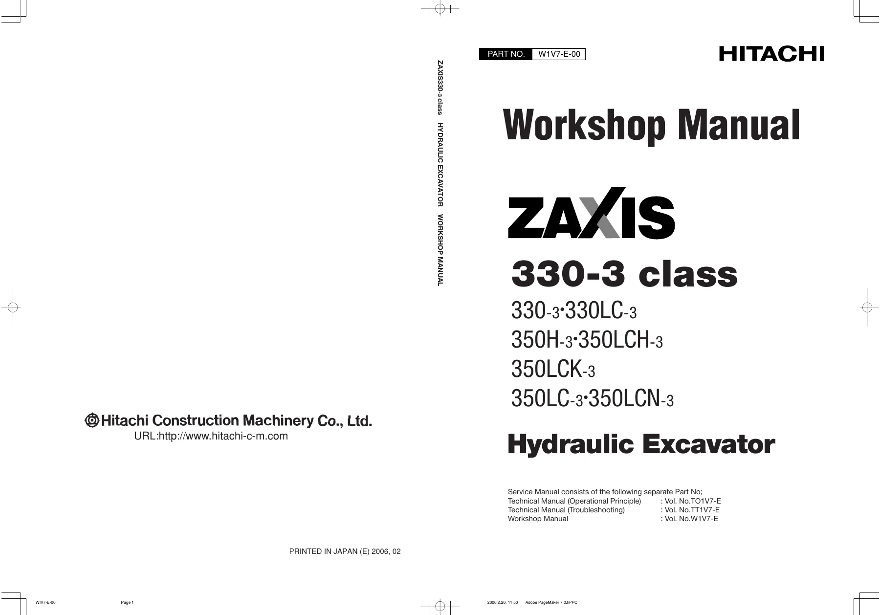
Hitachi Zaxis 330-3 Class Hydraulic Excavator Workshop Manual PDF – W1V7-E
Original price was: $39.95.$23.95Current price is: $23.95.
The complete Hitachi Zaxis 330-3 class Workshop Manual (W1V7-E) covering ZX330-3, ZX330LC-3, ZX350H-3, ZX350LCH-3, ZX350K-3, ZX350LCK-3, ZX350LC-3 and ZX350LCN-3 excavators. 490 pages of removal, installation, disassembly, assembly and maintenance-standard procedures for the upperstructure, undercarriage and front attachment.
Description
The Hitachi Zaxis 330-3 Class Hydraulic Excavator Workshop Manual is the W1V7-E workshop volume for the Zaxis 330-3 class – the hands-on half of the Zaxis service library that deals with taking components off the machine, stripping them down, measuring them against factory limits and building them back up. It covers the ZX330-3, ZX330LC-3, ZX350H-3, ZX350LCH-3, ZX350K-3, ZX350LCK-3, ZX350LC-3 and ZX350LCN-3 hydraulic excavators in one 490-page document.
Where the Technical Manual explains how systems operate and how to troubleshoot them, this Hitachi Zaxis 330-3 class workshop manual concentrates on the physical work: removal and installation sequences, disassembly and assembly order, the special tools called out for each job, and the maintenance standards that tell you whether a part goes back in or gets replaced.
File Details
- Manual type: Workshop Manual (maintenance and repair)
- Publication number: W1V7-E-00
- Brand: Hitachi
- Machine type: Hydraulic excavator
- Models covered: ZX330-3, ZX330LC-3, ZX350H-3, ZX350LCH-3, ZX350K-3, ZX350LCK-3, ZX350LC-3, ZX350LCN-3
- Language: English
- Pages: 490
- Format: PDF
- Revision date: July 2008
Chapters Covered
- Section 1 – General Information: precautions for disassembling and assembling; tightening torque specification, torque chart, piping joints and periodic replacement of parts; painting; bleeding air from the hydraulic oil tank
- Section 2 – Upperstructure: cab; counterweight; main frame; pump device (flange, main pump, pilot pump, coupling); control valve (4-spool and 5-spool side, housing split); swing device and swing motor; pilot valve (left, right, travel and positioning); pilot shut-off solenoid valve; signal control valve; 4-spool solenoid valve unit; engine
- Section 3 – Undercarriage: swing bearing; travel device and travel motor; brake valve; center joint; track adjuster; front idler; upper and lower roller; track
- Section 4 – Front Attachment: front attachment for mono boom and 2-piece boom; boom, arm, bucket and positioning cylinders
Read as a whole, the Hitachi Zaxis 330-3 class workshop manual gives a technician a component-level workflow that runs from the smallest seal to the whole upperstructure. Each group opens with the removal and installation of the assembly as a unit, then breaks that assembly down into its sub-components, lists the special tooling needed to handle them, and finishes with the maintenance standard – the measured dimension, clearance or wear limit that decides whether a part is reusable. There is no separate theory section here; the focus is squarely on what to unbolt, in what order, with what tool, and to what tolerance when it goes back together.
Workshop Procedures and Service Standards
Section 1 sets the working rules that apply everywhere else in the book. It explains how to clean and inspect a machine before it enters the shop, how to cap and plug open lines, how to match-mark parts, and how to handle components so contamination never reaches a sliding or sealing surface. O-rings, backup rings and oil seals are replaced whenever they are disturbed, and the manual repeats that instruction throughout.
The tightening torque group is one of the most referenced parts of the manual. It defines four bolt types used on the machine – hexagon T, hexagon H, hexagon M and socket bolts – and gives the specified tightening torque chart for each diameter and grade, with the torque tolerance stated as plus or minus ten percent. Alongside the chart are the correct tightening orders for multi-bolt flanges: alternate upper and lower bolts, tighten diagonally, or start from the centre and work outward diagonally, depending on the joint. Piping joint torque is separated out for union joints (30 degree male and 37 degree female), O-ring seal joints and screw-in connections, with the warning that over-tightening a union nut can crack the adapter.
The same section covers periodic replacement of parts, listing the fuel hoses, oil filter hose, heater hose, pump suction and delivery hoses, swing and travel hoses, and the boom, arm, bucket and pilot hoses that are replaced at fixed intervals regardless of apparent condition, together with the note that seals such as O-rings and gaskets should be renewed whenever a hose is replaced.
Handling instructions for floating seals, nylon slings and lifting equipment are included so that gearbox, idler and roller work can be done without damaging the very surfaces being repaired. Bleeding air from the hydraulic oil tank, the pump housing, the travel motor, the swing motor and the hydraulic circuit is written out as a step sequence, with the warning that starting the engine with air trapped in the pump housing can destroy the pump.
Undercarriage, Hydraulics and Front Attachment Work
The Zaxis 330-3 upperstructure section takes the technician through cab removal with its weight noted for lifting, counterweight removal and installation with the differing bolt torques between the 330 and 350 variants, main frame separation from the undercarriage, and the swing bearing mounting angle and matching-mark procedure that has to be followed if the soft zone is not to end up in the wrong position.
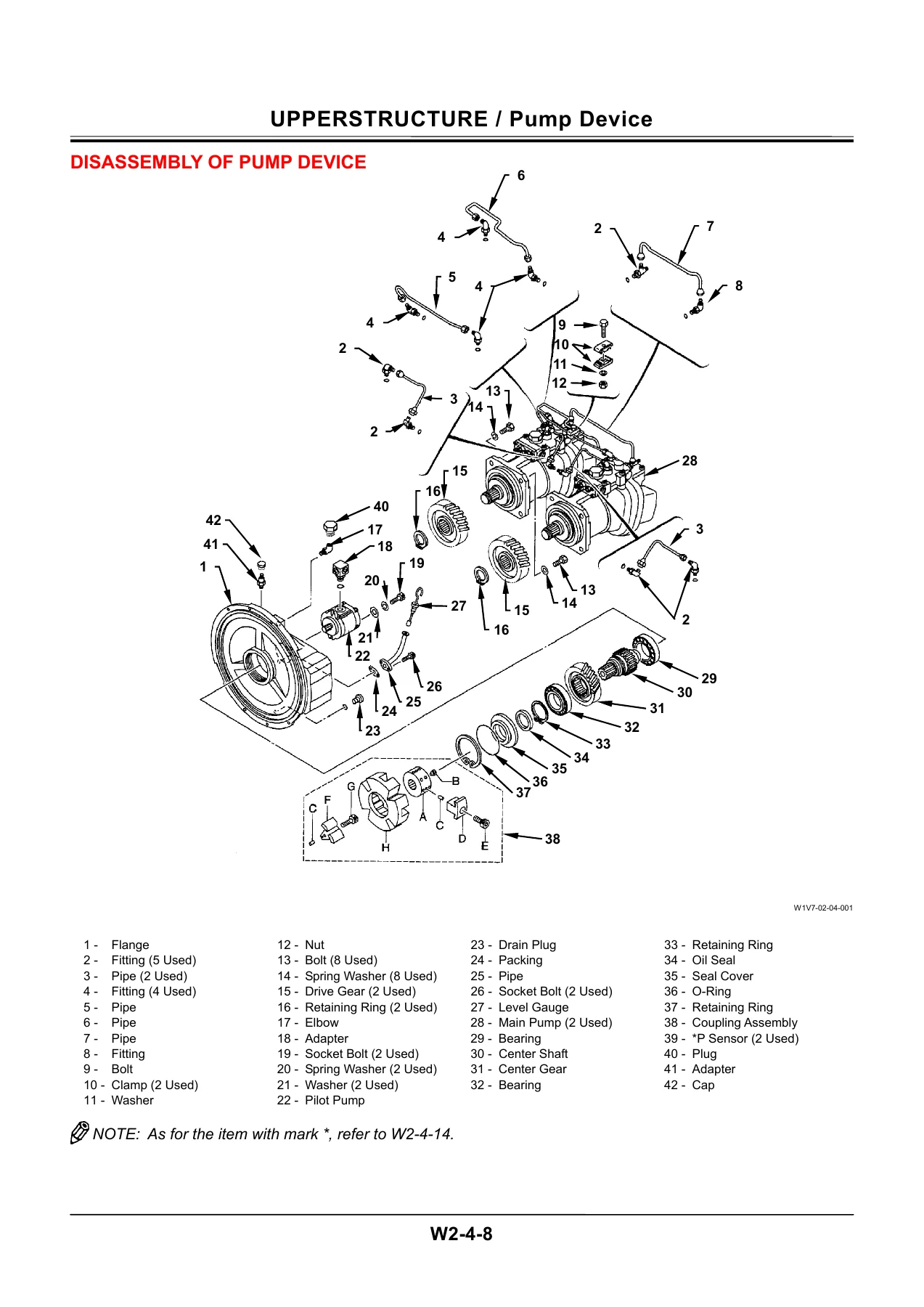
The pump device group covers removing both main pumps, the pilot pump and the coupling assembly, then disassembling the flange, centre shaft, centre gear and bearings using the designated special tools, and reassembling the pump with the bearing preload measured as a starting torque figure. The control valve group is split across the 4-spool and 5-spool sides, with the spool assemblies, check valves, overload relief valves, boom anti-drift valve, flow combiner valve, bucket and arm flow rate control valves and bypass shut-out valve all broken out separately, and the instruction that the main relief valve and overload relief valves are not to be disassembled unless pressure is going to be re-adjusted afterwards.
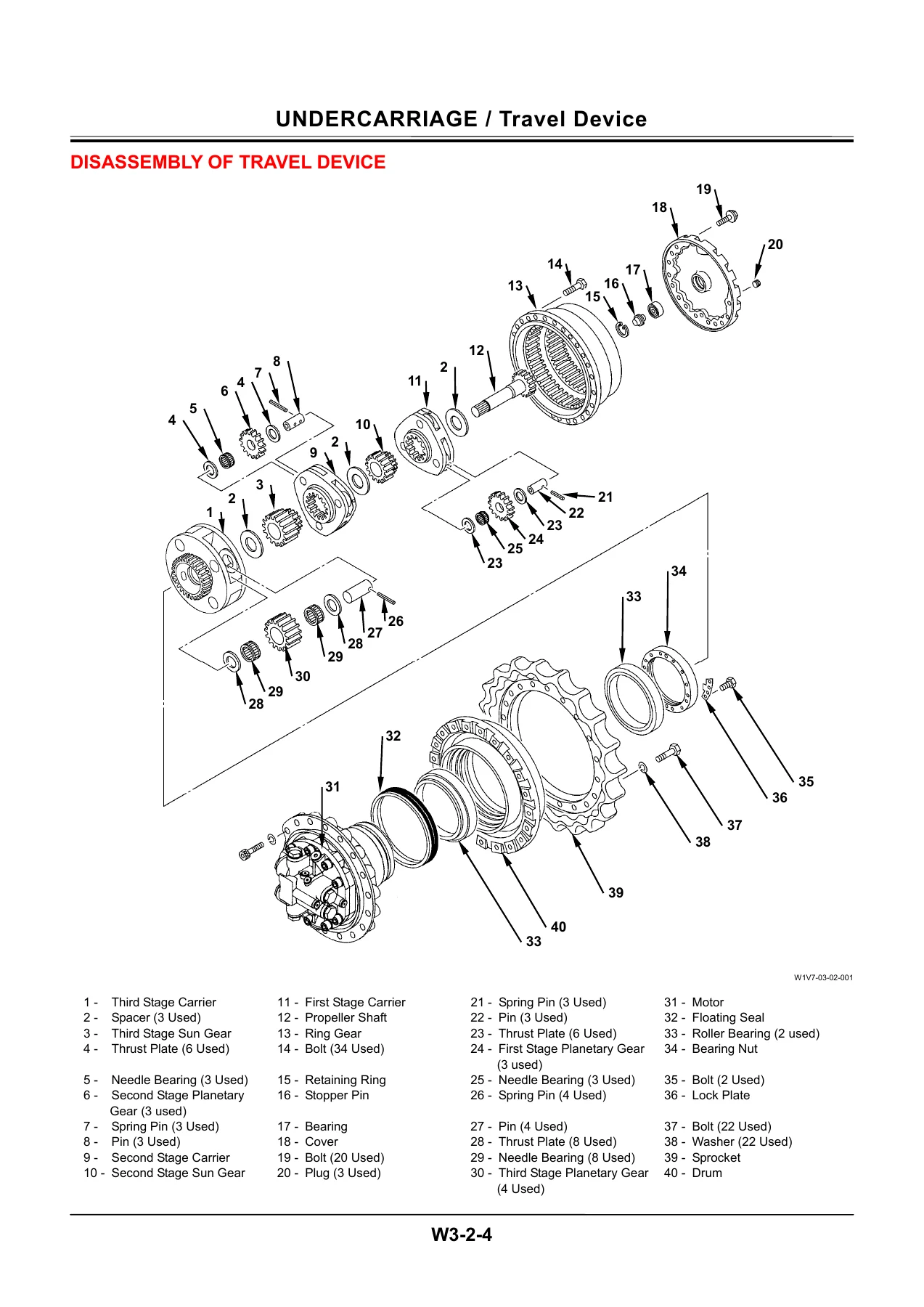
Travel device coverage runs through removal of the unit from the track frame, stripping the three-stage planetary reduction, removing the bearing nut with the correct special tools, and reassembling with the bearing preload set by tightening, tapping and rotating the sprocket a set number of turns before final torque. The travel motor and brake valve are disassembled separately, including the caution that the brake piston is removed with low-pressure air behind a cloth so it cannot fly out. The swing device and swing motor follow the same pattern, with the parking brake switch valve detailed as its own structure drawing.
Undercarriage coverage continues with the centre joint, track adjuster, front idler, upper and lower rollers and the track itself. The track adjuster is one of the more carefully documented jobs because of the stored spring energy – the manual specifies a pump unit with a maximum pressure of 69 MPa and a main relief setting of 49 MPa or lower, describes compressing the spring until the clearance between washer and nut is about 10 mm, and requires the special tool to be inspected for damage before the work starts.
Section 4 handles the front attachment for both the mono boom and the 2-piece boom, including the hydraulic circuit pressure release procedure, removal and installation of the complete front assembly with its lifting weights for each model, and the cylinder group – boom, arm, bucket and positioning – with disassembly and assembly of each cylinder, nut torques, set screw caulking and rod bend and run-out limits.
Why This Manual Matters
Excavator repair goes wrong in predictable places: a bolt tightened to the wrong figure, a bearing nut set without preload, a floating seal installed dry, a spool put back in the wrong bore, or a spring released without the right fixture. This Hitachi Zaxis 330-3 class hydraulic excavator workshop manual removes that guesswork by giving the exact procedure, the exact tool, and the exact number for every one of those steps across the upperstructure, undercarriage and front attachment.
With it you can pull and refit the cab, counterweight and main frame; strip and rebuild both main pumps and the pilot pump; work through the control valve down to individual spools, check valves and relief valves; rebuild the swing motor, travel motor and brake valve; service the centre joint, track adjuster, idler and rollers; and overhaul all four cylinder types on the front attachment. Maintenance standards with allowable limits are given for the swing motor, travel motor, sprocket, front idler, rollers, track links, pins and bushings, so worn parts can be identified by measurement rather than by guesswork.
IMAGES PREVIEW
The file is delivered as an instant PDF download – no shipping, no waiting for a courier. Open it on a laptop, tablet or phone in the workshop, print the pages for the job in front of you, and keep the full manual on hand for the next one.



Reviews
There are no reviews yet.